Page 408 of 1306
7 CHECK FUEL PUMP RELAY
With CONSULT-II
1. Reconnect fuel pump relay, fuel level sensor unit and fuel pump harness connector and ECM harness connector.
2. Turn ignition switch ON.
3. Turn fuel pump relay ªONº and ªOFFº in ªACTIVE TESTº mode with CONSULT-II and check operating sound.
SEF724Z
Without CONSULT-II
Check continuity between terminals 3 and 5.
PBIB0098E
MTBL0306
OK or NG
OK©GO TO 8.
NG©Replace fuel pump relay.
FUEL PUMPKA24DE (EURO OBD)
Diagnostic Procedure
EC-3383
Page 414 of 1306
SEF342V
Component DescriptionNEEC0462When the air conditioner is on, the IACV-FICD solenoid valve sup-
plies additional air to adjust to the increased load.
ECM Terminals and Reference ValueNEEC0463Specification data are reference values and are measured between each terminal and ground.
CAUTION:
Do not use ECM ground terminals when measuring input/output voltage. Doing so may result in dam-
age to the ECM's transistor. Use a ground other than ECM terminals, such as the ground.
TERMI-
NAL
NO.WIRE
COLORITEM CONDITION DATA (DC Voltage)
12 G/W Air conditioner relay[Engine is running]
+Both A/C switch and blower switch are ONHApproximately 0V
[Engine is running]
+A/C switch is OFFBATTERY VOLTAGE
(11 - 14V)
HAmbient air temperature above 10ÉC (50ÉF) and in any mode except OFF.
IACV-FICD SOLENOID VALVEKA24DE (EURO OBD)
Component Description
EC-3389
Page 418 of 1306
3 CHECK POWER SUPPLY
1. Stop engine.
2. Disconnect IACV-FICD solenoid valve harness connector.
SEF342V
3. Start engine, then push A/C switch ON and turn fan switch to 4-speed.
4. Check voltage between terminal 1 and ground with CONSULT-II or tester.
SEC281D
Voltage: Battery voltage
OK or NG
OK©GO TO 5.
NG©GO TO 4.
4 DETECT MALFUNCTIONING PART
Check the following.
+Harness connectors E101, M5
+Harness for open or short between IACV-FICD solenoid valve and air conditioner relay
©Repair open circuit, short to ground or short to power in harness or connectors.
IACV-FICD SOLENOID VALVEKA24DE (EURO OBD)
Diagnostic Procedure
EC-3393
Page 419 of 1306

5 CHECK GROUND CIRCUIT
1. Turn ignition switch OFF.
2. Check harness continuity as follows.
MTBL1310
Continuity should exist.
3. Also check harness for short to ground or short to power.
OK or NG
OK©GO TO 7.
NG©GO TO 6.
6 DETECT MALFUNCTIONING PART
MANUAL AIR CONDITIONER
Check the following.
+Harness connectors E101, M5
+IACV-FICD solenoid valve
+Ambient temperature switch
+Diode M83
+Harness connectors M5, E101
+Check the harness for open or short between air conditioner relay and ambient temperature switch
+Check the harness for open or short between diode M83 and ECM
+Check the harness for open or short between ambient temperature switch and ECM
+Check the harness for open or short between ambient temperature switch and ground
AUTO AIR CONDITIONER
Check the following.
+Harness connectors E101, M5
+IACV-FICD solenoid valve
+Diode M83
+Check the harness for open or short between air conditioner relay and ECM
+Check the harness for open or short between diode and A/C auto amp
+Check the harness for open or short between A/C auto amp and ECM
©Repair open circuit or short to power in harness or connectors.
IACV-FICD SOLENOID VALVEKA24DE (EURO OBD)
Diagnostic Procedure
EC-3394
Page 435 of 1306
System Chart
Input (Sensor) ECM Function Output (Actuator)
+Electronic control fuel injection pump
+Crankshaft position sensor (TDC)
+Engine coolant temperature sensor
+Accelerator position sensor
+Accelerator position switch
+Park/Neutral position (PNP) switch
+Ignition switch
+Battery voltage
+Vehicle speed sensor
+Air conditioner switch
+Stop lamp switch
+Charge air pressure sensor
+Intake air temperature sensorFuel injection control Electronic control fuel injection pump
Fuel injection timing control Electronic control fuel injection pump
Fuel cut control Electronic control fuel injection pump
Glow control system Glow relay & glow lamp
On board diagnostic system MIL (On the instrument panel)
EGR volume control EGR volume control valve
Cooling fan control Cooling fan relay
Air conditioning cut control Air conditioner relay
ENGINE AND EMISSION CONTROL OVERALL SYSTEMYD25DDTi
EC-3410
Page 438 of 1306

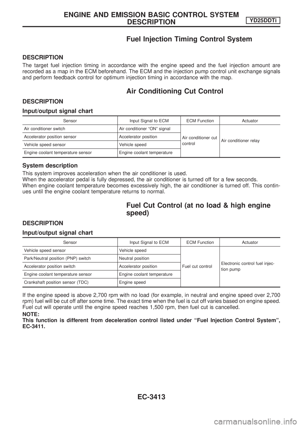
Fuel Injection Timing Control System
DESCRIPTION
The target fuel injection timing in accordance with the engine speed and the fuel injection amount are
recorded as a map in the ECM beforehand. The ECM and the injection pump control unit exchange signals
and perform feedback control for optimum injection timing in accordance with the map.
Air Conditioning Cut Control
DESCRIPTION
Input/output signal chart
Sensor Input Signal to ECM ECM Function Actuator
Air conditioner switch Air conditioner ªONº signal
Air conditioner cut
controlAir conditioner relay Accelerator position sensor Accelerator position
Vehicle speed sensor Vehicle speed
Engine coolant temperature sensor Engine coolant temperature
System description
This system improves acceleration when the air conditioner is used.
When the accelerator pedal is fully depressed, the air conditioner is turned off for a few seconds.
When engine coolant temperature becomes excessively high, the air conditioner is turned off. This contin-
ues until the engine coolant temperature returns to normal.
Fuel Cut Control (at no load & high engine
speed)
DESCRIPTION
Input/output signal chart
Sensor Input Signal to ECM ECM Function Actuator
Vehicle speed sensor Vehicle speed
Fuel cut controlElectronic control fuel injec-
tion pump Park/Neutral position (PNP) switch Neutral position
Accelerator position switch Accelerator position
Engine coolant temperature sensor Engine coolant temperature
Crankshaft position sensor (TDC) Engine speed
If the engine speed is above 2,700 rpm with no load (for example, in neutral and engine speed over 2,700
rpm) fuel will be cut off after some time. The exact time when the fuel is cut off varies based on engine speed.
Fuel cut will operate until the engine speed reaches 1,500 rpm, then fuel cut is cancelled.
NOTE:
This function is different from deceleration control listed under ªFuel Injection Control Systemº,
EC-3411.
ENGINE AND EMISSION BASIC CONTROL SYSTEM
DESCRIPTIONYD25DDTi
EC-3413
Page 460 of 1306

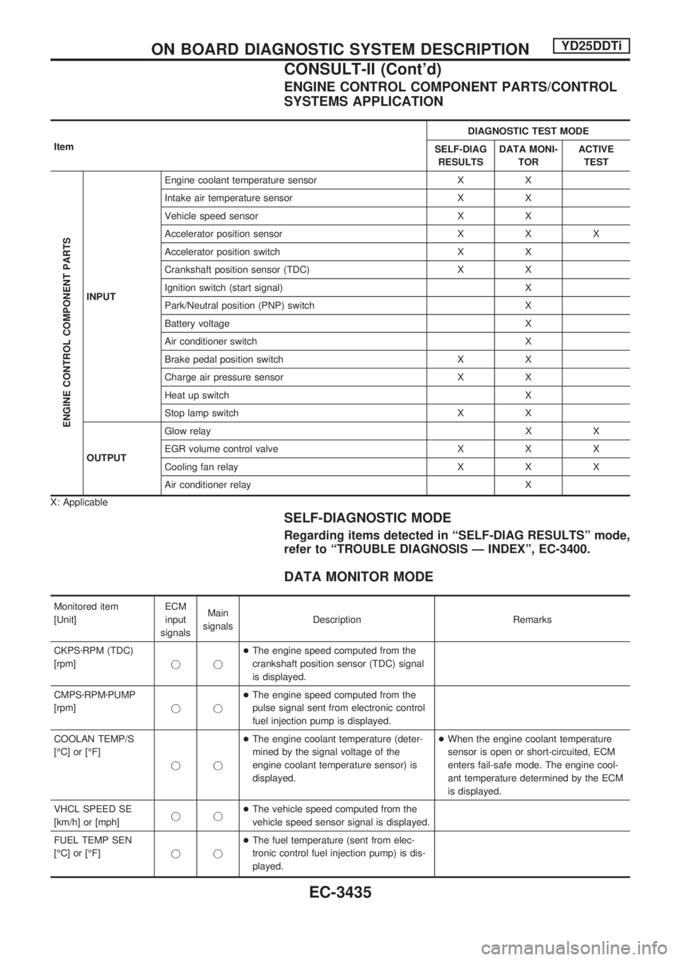
ENGINE CONTROL COMPONENT PARTS/CONTROL
SYSTEMS APPLICATION
ItemDIAGNOSTIC TEST MODE
SELF-DIAG
RESULTSDATA MONI-
TORACTIVE
TEST
ENGINE CONTROL COMPONENT PARTS
INPUTEngine coolant temperature sensor X X
Intake air temperature sensor X X
Vehicle speed sensor X X
Accelerator position sensor X X X
Accelerator position switch X X
Crankshaft position sensor (TDC) X X
Ignition switch (start signal) X
Park/Neutral position (PNP) switch X
Battery voltage X
Air conditioner switch X
Brake pedal position switch X X
Charge air pressure sensor X X
Heat up switch X
Stop lamp switch X X
OUTPUTGlow relayXX
EGR volume control valve X X X
Cooling fan relay X X X
Air conditioner relay X
X: Applicable
SELF-DIAGNOSTIC MODE
Regarding items detected in ªSELF-DIAG RESULTSº mode,
refer to ªTROUBLE DIAGNOSIS Ð INDEXº, EC-3400.
DATA MONITOR MODE
Monitored item
[Unit]ECM
input
signalsMain
signalsDescription Remarks
CKPSzRPM (TDC)
[rpm]jj+The engine speed computed from the
crankshaft position sensor (TDC) signal
is displayed.
CMPSzRPMzPUMP
[rpm]jj+The engine speed computed from the
pulse signal sent from electronic control
fuel injection pump is displayed.
COOLAN TEMP/S
[ÉC] or [ÉF]
jj+The engine coolant temperature (deter-
mined by the signal voltage of the
engine coolant temperature sensor) is
displayed.+When the engine coolant temperature
sensor is open or short-circuited, ECM
enters fail-safe mode. The engine cool-
ant temperature determined by the ECM
is displayed.
VHCL SPEED SE
[km/h] or [mph]jj+The vehicle speed computed from the
vehicle speed sensor signal is displayed.
FUEL TEMP SEN
[ÉC] or [ÉF]jj+The fuel temperature (sent from elec-
tronic control fuel injection pump) is dis-
played.
ON BOARD DIAGNOSTIC SYSTEM DESCRIPTIONYD25DDTi
CONSULT-II (Cont'd)
EC-3435
Page 461 of 1306
![NISSAN PICK-UP 2001 Repair Manual Monitored item
[Unit]ECM
input
signalsMain
signalsDescription Remarks
ACCEL POS SEN [V]
jj+The accelerator position sensor signal
voltage is displayed.
FULL ACCEL SW
[ON/OFF]jj+Indicates [ON/OFF] cond NISSAN PICK-UP 2001 Repair Manual Monitored item
[Unit]ECM
input
signalsMain
signalsDescription Remarks
ACCEL POS SEN [V]
jj+The accelerator position sensor signal
voltage is displayed.
FULL ACCEL SW
[ON/OFF]jj+Indicates [ON/OFF] cond](/manual-img/5/57372/w960_57372-460.png)
Monitored item
[Unit]ECM
input
signalsMain
signalsDescription Remarks
ACCEL POS SEN [V]
jj+The accelerator position sensor signal
voltage is displayed.
FULL ACCEL SW
[ON/OFF]jj+Indicates [ON/OFF] condition from the
accelerator position switch signal.
OFF ACCEL SW
[ON/OFF]jj+Indicates [ON/OFF] condition from the
accelerator position switch signal.
SPILL/V [ÉCA]
j+The control position of spill valve (sent
from electronic control fuel injection
pump) is displayed.
BATTERY VOLT [V]
jj+The power supply voltage of ECM is dis-
played.
I/C INT/A T/S [V]
jj+The signal voltage of the intake air tem-
perature sensor is displayed.
P/N POSI SW
[ON/OFF]jj+Indicates [ON/OFF] condition from the
park/neutral position switch signal.
START SIGNAL
[ON/OFF]jj+Indicates [ON/OFF] condition from the
starter signal.+After starting the engine, [OFF] is dis-
played regardless of the starter signal.
AIR COND SIG
[ON/OFF]jj+Indicates [ON/OFF] condition of the air
conditioner switch as determined by the
air conditioner signal.
BRAKE SW [ON/OFF]
jj+Indicates [ON/OFF] condition from the
stop lamp switch signal.
BRAKE SW2
[ON/OFF]jj+Indicates [ON/OFF] condition from the
brake pedal position switch.
IGN SW
[ON/OFF]jj+Indicates [ON/OFF] condition from igni-
tion switch signal.
WARM UP SW
[ON/OFF]j+Indicates [ON/OFF] condition from the
heat up switch signal.
TURBO BST SEN
[kPa]j+The charge air pressure (determined by
the signal voltage sent to the ECM) is
displayed.
DECELER F/CUT
[ON/OFF]j+The [ON/OFF] condition from decelera-
tion fuel cut signal (sent from ECM) is
displayed.
INJ TIMG C/V [%]
j+The duty ratio of fuel injection timing
control valve (sent from electronic con-
trol fuel injection pump) is displayed.
AIR COND RLY
[ON/OFF]j+Indicates the control condition of the air
conditioner relay (determined by ECM
according to the input signals).
GLOW RLY [ON/OFF]
j+The glow relay control condition (deter-
mined by ECM according to the input
signal) is displayed.
COOLING FAN
[ON/OFF]
j+Indicates the control condition of the
cooling fans (determined by ECM
according to the input signal).
+ON ... Operates.
OFF ... Stopped.
ON BOARD DIAGNOSTIC SYSTEM DESCRIPTIONYD25DDTi
CONSULT-II (Cont'd)
EC-3436