2001 NISSAN PICK-UP hood release
[x] Cancel search: hood releasePage 303 of 1306

SEF484YE
On Board Diagnosis LogicNEEC1050The ECM monitors the switching frequency ratio of heated oxygen
sensor 1 and 2.
A three way catalyst with high oxygen storage capacity will indicate
a low switching frequency of heated oxygen sensor 2. As oxygen
storage capacity decreases, the heated oxygen sensor 2 switching
frequency will increase.
When the frequency ratio of heated oxygen sensors 1 and 2
approaches a specified limit value, the three way catalyst malfunc-
tion is diagnosed.
DTC No. Malfunction is detected when ... Check Items (Possible Cause)
P0420
0420+Three way catalyst does not operate properly.
+Three way catalyst does not have enough oxygen stor-
age capacity.+Three way catalyst
+Exhaust tube
+Intake air leaks
+Injectors
+Injector leaks
+Spark plug
+Improper ignition timing
PBIB0566E
PBIB0567E
DTC Confirmation ProcedureNEEC1051NOTE:
If ªDTC Confirmation Procedureº has been previously
conducted, always turn ignition switch ªOFFº and wait at least
5 seconds before conducting the next test.
TESTING CONDITION:
+Open engine hood before conducting following proce-
dure.
+Do not hold engine speed more than specified minutes
below.
With CONSULT-II
1) Turn ignition switch ªONº.
2) Select ªDTC & SRT CONFIRMATIONº then ªSRT WORK SUP-
PORTº mode with CONSULT-II.
3) Start engine.
4) Rev engine up to 2,500 to 3,500 rpm and hold it for 3 consecu-
tive minutes then release then accelerator pedal completely.
If ªINCMPº of ªCATALYSTº changes to ªCMPLTº, go to step 7.
5) Wait 5 seconds at idle.
6) Rev engine up to 2,500 to 3,500 rpm and hold it until ªINCMPº
of ªCATALYSTº changes to ªCMPLTº. (It will take maximum of
approximately 5 minute.)
SEF560X
7) Select ªSELF-DIAG RESULTSº mode with CONSULT-II.
If the 1st trip DTC is detected, go to ªDIAGNOSTIC
PROCEDUREº, EC-3280. If not ªCOMPLTº stop engine and
cool down ªCOOLANT TEMP/SEº to less than 70ÉC (158ÉF)
and then retest from step 1).
DTC P0420 THREE WAY CATALYST
FUNCTION
KA24DE (EURO OBD)
On Board Diagnosis Logic
EC-3278
Page 814 of 1306

ID Code Entry Procedure
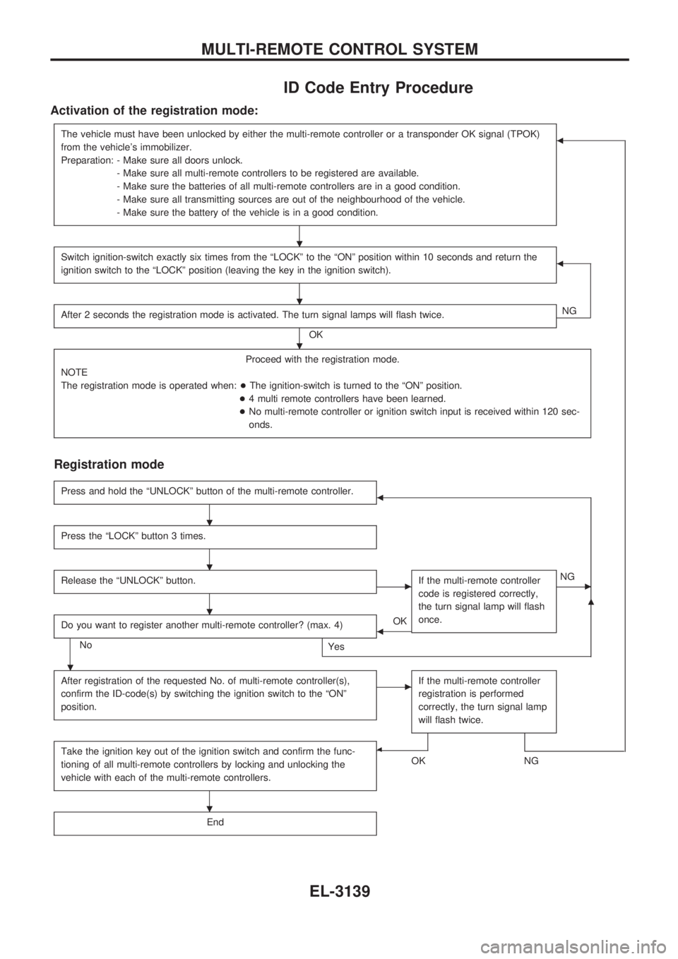
Activation of the registration mode:
The vehicle must have been unlocked by either the multi-remote controller or a transponder OK signal (TPOK)
from the vehicle's immobilizer.
Preparation: - Make sure all doors unlock.
- Make sure all multi-remote controllers to be registered are available.
- Make sure the batteries of all multi-remote controllers are in a good condition.
- Make sure all transmitting sources are out of the neighbourhood of the vehicle.
- Make sure the battery of the vehicle is in a good condition.b
Switch ignition-switch exactly six times from the ªLOCKº to the ªONº position within 10 seconds and return the
ignition switch to the ªLOCKº position (leaving the key in the ignition switch).b
After 2 seconds the registration mode is activated. The turn signal lamps will flash twice.
OKNG
Proceed with the registration mode.
NOTE
The registration mode is operated when:+The ignition-switch is turned to the ªONº position.
+4 multi remote controllers have been learned.
+No multi-remote controller or ignition switch input is received within 120 sec-
onds.
Registration mode
Press and hold the ªUNLOCKº button of the multi-remote controller.b
Press the ªLOCKº button 3 times.
Release the ªUNLOCKº button.cIf the multi-remote controller
code is registered correctly,
the turn signal lamp will flash
once.cNG
Do you want to register another multi-remote controller? (max. 4)
No
Yes
bOK
m
After registration of the requested No. of multi-remote controller(s),
confirm the ID-code(s) by switching the ignition switch to the ªONº
position.cIf the multi-remote controller
registration is performed
correctly, the turn signal lamp
will flash twice.
Take the ignition key out of the ignition switch and confirm the func-
tioning of all multi-remote controllers by locking and unlocking the
vehicle with each of the multi-remote controllers.b
OKNG
End
.
.
.
.
.
.
.
.
MULTI-REMOTE CONTROL SYSTEM
EL-3139
Page 1063 of 1306

EGR volume control valve .......... EC-3605, 3606
EVAP canister purge volume control
solenoid valve ................................... EC-3283
EVAP canister ....................................... EC-3029
Electrical ignition system ...................... EC-3026
Electronic fuel injection
pump ........ EC-3419, 3420, 3508, 3509, 3542,
3543, 3549, 3550, 3556, 3557,
3563, 3564, 3570, 3571, 3573,
3574, 3614, 3615
Engine control circuit
diagram ......................... EC-3020, 3408, 3409
Engine control component parts
location .............................................. EC-3018
Engine control module (ECM) .............. EC-3308
Engine control system diagram and
chart .............................. EC-3021, 3409, 3410
Engine coolant temperature sensor
(ECTS) .......................... EC-3165, 3480, 3481
Engine fail-safe system ......................... EC-3101
Engine oil filter replacement ................. MA-3013
Engine oil replacement ......................... MA-3012
Engine outer component parts ............. EM-3008
Engine removal ..................................... EM-3063
Engine serial number ............................. GI-3006
Evaporative emission (EVAP)
system ............................................... EC-3029
Exhaust system ..................................... FE-3005
Exterior .................................................. BT-3006
F
F/PUMP - Wiring diagram ..................... EC-3380
FICD - Wiring diagram .......................... EC-3390
FUEL - Wiring diagram ............... EC-3239, 3246
Fast idle cam (FIC) ............................... EC-3035
Fluids .................................................... MA-3008
Flywheel runout .................................... EM-3080
Fog lamp, rear ....................................... EL-3045
Freeze frame data ................................ EC-3050
Front bumper ......................................... BT-3002
Front case (Transfer) ............................. TF-3003
Front combination lamp removal and
installation .......................................... BT-3002
Front drive shaft (Transfer) ................... TF-3004
Front passenger air bag ............. RS-3003, 3009
Fuel cut control (at no load & high
engine speed) ............... EC-3028, 3413, 3414
Fuel filter replacement .......................... MA-3018
Fuel filter ............................................... EC-3033
Fuel injection system ................. EC-3237, 3244,
3411, 3412
Fuel injector .......................................... EC-3369
Fuel line inspection ............................... MA-3019
Fuel pressure check ............................. EC-3033
Fuel pressure regulator ......................... EC-3034
Fuel pressure release ........................... EC-3033
Fuel pump relay .................................... EC-3378
Fuel pump ............................................. EC-3378Fuel system ........................................... FE-3003
Fuel tank vacuum relief valve ............... EC-3030
Fuse block ............................................. EL-3199
G
Gauges .................................................. EL-3056
Generic scan tool (GST) ....................... EC-3080
Glow plug .................................... EC-3621, 3622
Glow relay ................................... EC-3621, 3622
Grease .................................................. MA-3008
H
H/AIM - Wiring diagram ......................... EL-3037
H/LAMP - Wiring diagram ..................... EL-3023
HEAT UP - Wiring diagram ........ EC-3639, 3640
HEATER - Wiring diagram .................... HA-3004
HLC - Wiring diagram ............................ EL-3108
HORN - Wiring diagram ........................ EL-3109
HSEAT - Wiring diagram ....................... EL-3118
Harness layout ....................................... EL-3166
Hazard warning lamp ............................ EL-3047
Headlamp aiming control ....................... EL-3037
Headlamp removal and installation ....... BT-3002
Headlamp washer .................................. EL-3108
Headlamp .............................................. EL-3023
Heat up switch ............................ EC-3638, 3639
Heated oxygen sensor (HO2S)
(front) ........ EC-3202, 3213, 3196, 3310, 3317
Heated oxygen sensor (HO2S) heater
(front) ................................................. EC-3133
Heated oxygen sensor (HO2S) heater
(rear) .................................................. EC-3138
Heated oxygen sensor
(rear) ................... EC-3220, 3227, 3324, 3334
Heated seat ........................................... EL-3118
Hood ...................................................... BT-3002
Horn ....................................................... EL-3109
How to erase DTC for OBD
system ........................... EC-3060, 3428, 3429
I
IACV-AAC valve .................................... EC-3295
IACV-FICD solenoid valve .................... EC-3389
IATS - Wiring diagram ...... EC-3162, 3505, 3506
ILL - Wiring diagram .............................. EL-3050
INJECT - Wiring diagram ...................... EC-3370
INT/L - Wiring diagram .......................... EL-3055
Idle air control (IAC) system ................. EC-3295
Idle air control valve (IACV) .................. EC-3295
Idle mixture ratio ................................... EC-3035
Idle speed ......................... EC-3035, 3444, 3445
Ignition control system .......................... EC-3361
Ignition timing ........................................ EC-3035
Illumination ............................................. EL-3050
ALPHABETICAL INDEX
IDX-3003
Page 1250 of 1306

ID Code Entry Procedure
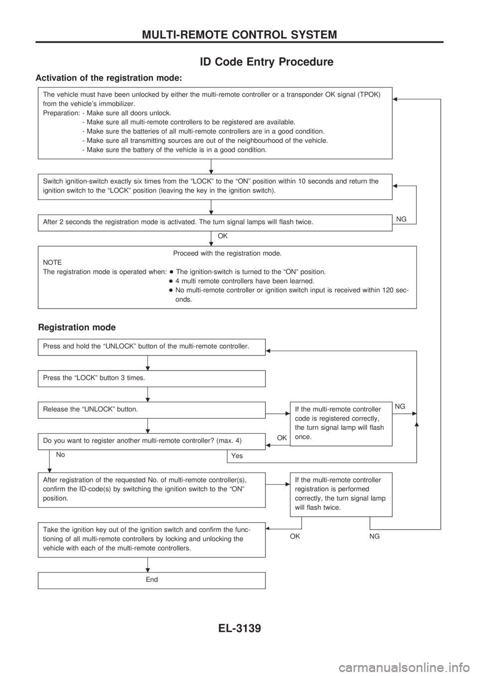
Activation of the registration mode:
The vehicle must have been unlocked by either the multi-remote controller or a transponder OK signal (TPOK)
from the vehicle's immobilizer.
Preparation: - Make sure all doors unlock.
- Make sure all multi-remote controllers to be registered are available.
- Make sure the batteries of all multi-remote controllers are in a good condition.
- Make sure all transmitting sources are out of the neighbourhood of the vehicle.
- Make sure the battery of the vehicle is in a good condition.b
Switch ignition-switch exactly six times from the ªLOCKº to the ªONº position within 10 seconds and return the
ignition switch to the ªLOCKº position (leaving the key in the ignition switch).b
After 2 seconds the registration mode is activated. The turn signal lamps will flash twice.
OKNG
Proceed with the registration mode.
NOTE
The registration mode is operated when:+The ignition-switch is turned to the ªONº position.
+4 multi remote controllers have been learned.
+No multi-remote controller or ignition switch input is received within 120 sec-
onds.
Registration mode
Press and hold the ªUNLOCKº button of the multi-remote controller.b
Press the ªLOCKº button 3 times.
Release the ªUNLOCKº button.cIf the multi-remote controller
code is registered correctly,
the turn signal lamp will flash
once.cNG
Do you want to register another multi-remote controller? (max. 4)
No
Yes
bOK
m
After registration of the requested No. of multi-remote controller(s),
confirm the ID-code(s) by switching the ignition switch to the ªONº
position.cIf the multi-remote controller
registration is performed
correctly, the turn signal lamp
will flash twice.
Take the ignition key out of the ignition switch and confirm the func-
tioning of all multi-remote controllers by locking and unlocking the
vehicle with each of the multi-remote controllers.b
OKNG
End
.
.
.
.
.
.
.
.
MULTI-REMOTE CONTROL SYSTEM
EL-3139