Page 908 of 1306
1. Install rear chain case.
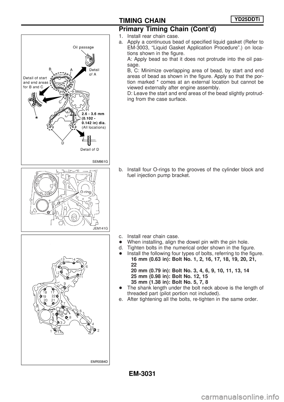
a. Apply a continuous bead of specified liquid gasket (Refer to
EM-3003, ªLiquid Gasket Application Procedureº.) on loca-
tions shown in the figure.
A: Apply bead so that it does not protrude into the oil pas-
sage.
B, C: Minimize overlapping area of bead, by start and end
areas of bead as shown in the figure. Apply so that the por-
tion marked * comes at an external location but cannot be
viewed externally after engine assembly.
D: Leave the start and end areas of the bead slightly protrud-
ing from the case surface.
b. Install four O-rings to the grooves of the cylinder block and
fuel injection pump bracket.
c. Install rear chain case.
+When installing, align the dowel pin with the pin hole.
d. Tighten bolts in the numerical order shown in the figure.
+Install the following four types of bolts, referring to the figure.
16 mm (0.63 in): Bolt No. 1, 2, 16, 17, 18, 19, 20, 21,
22
20 mm (0.79 in): Bolt No. 3, 4, 6, 9, 10, 11, 13, 14
25 mm (0.98 in): Bolt No. 12, 15
35 mm (1.38 in): Bolt No. 5, 7, 8
+The shank length under the bolt neck above is the length of
threaded part (pilot portion not included).
e. After tightening all the bolts, re-tighten in the same order.
SEM861G
JEM141G
EMR0084D
TIMING CHAINYD25DDTi
Primary Timing Chain (Cont'd)
EM-3031
Page 949 of 1306
Refer to SDS (EM-3094).
+When replacing the piston, check the cylinder block surface
for scratches or seizure. If scratches or seizure is found,
hone or replace the cylinder block.
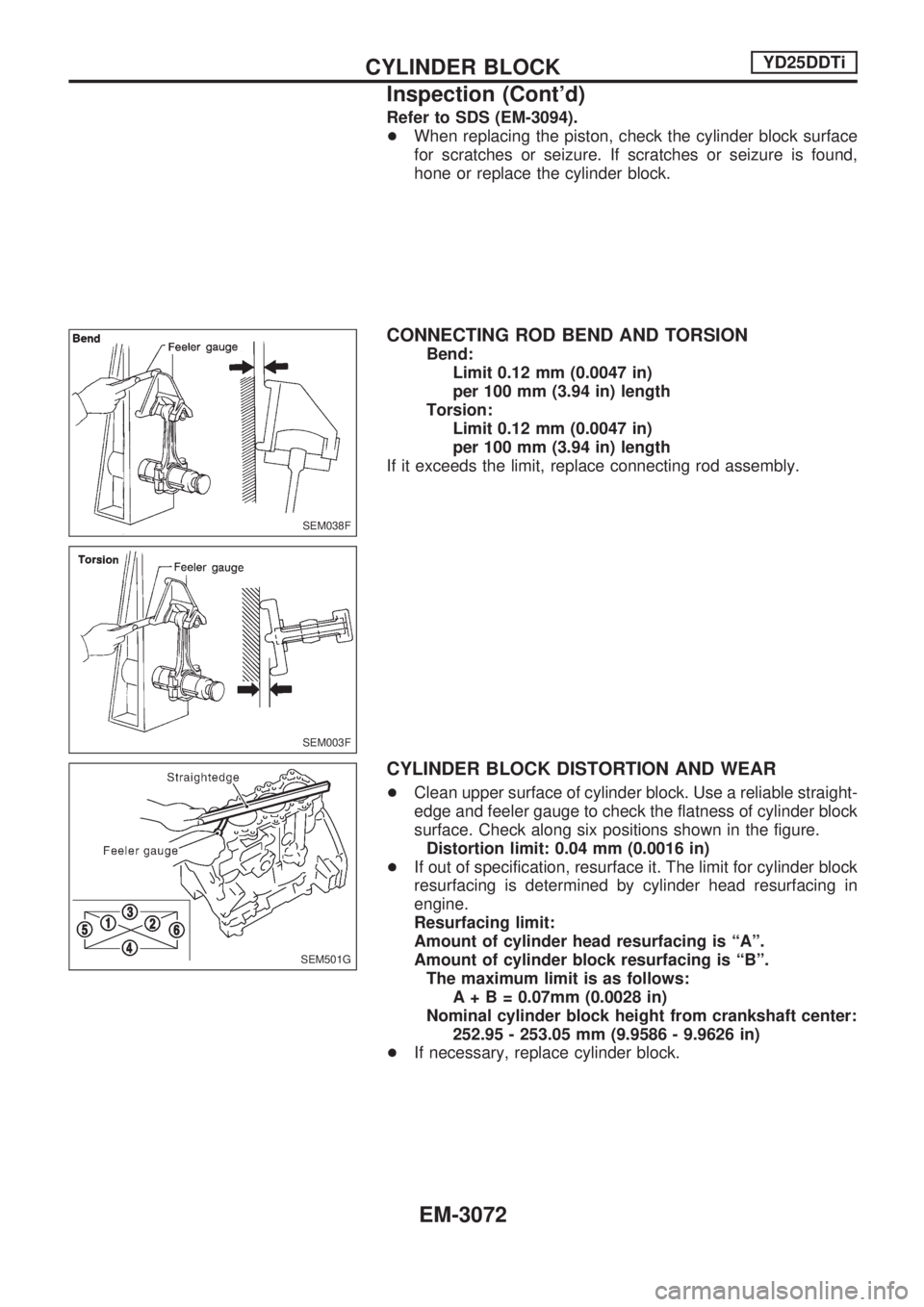
CONNECTING ROD BEND AND TORSION
Bend:
Limit 0.12 mm (0.0047 in)
per 100 mm (3.94 in) length
Torsion:
Limit 0.12 mm (0.0047 in)
per 100 mm (3.94 in) length
If it exceeds the limit, replace connecting rod assembly.
CYLINDER BLOCK DISTORTION AND WEAR
+Clean upper surface of cylinder block. Use a reliable straight-
edge and feeler gauge to check the flatness of cylinder block
surface. Check along six positions shown in the figure.
Distortion limit: 0.04 mm (0.0016 in)
+If out of specification, resurface it. The limit for cylinder block
resurfacing is determined by cylinder head resurfacing in
engine.
Resurfacing limit:
Amount of cylinder head resurfacing is ªAº.
Amount of cylinder block resurfacing is ªBº.
The maximum limit is as follows:
A+B=0.07mm (0.0028 in)
Nominal cylinder block height from crankshaft center:
252.95 - 253.05 mm (9.9586 - 9.9626 in)
+If necessary, replace cylinder block.
SEM038F
SEM003F
SEM501G
CYLINDER BLOCKYD25DDTi
Inspection (Cont'd)
EM-3072
Page 966 of 1306
Valve
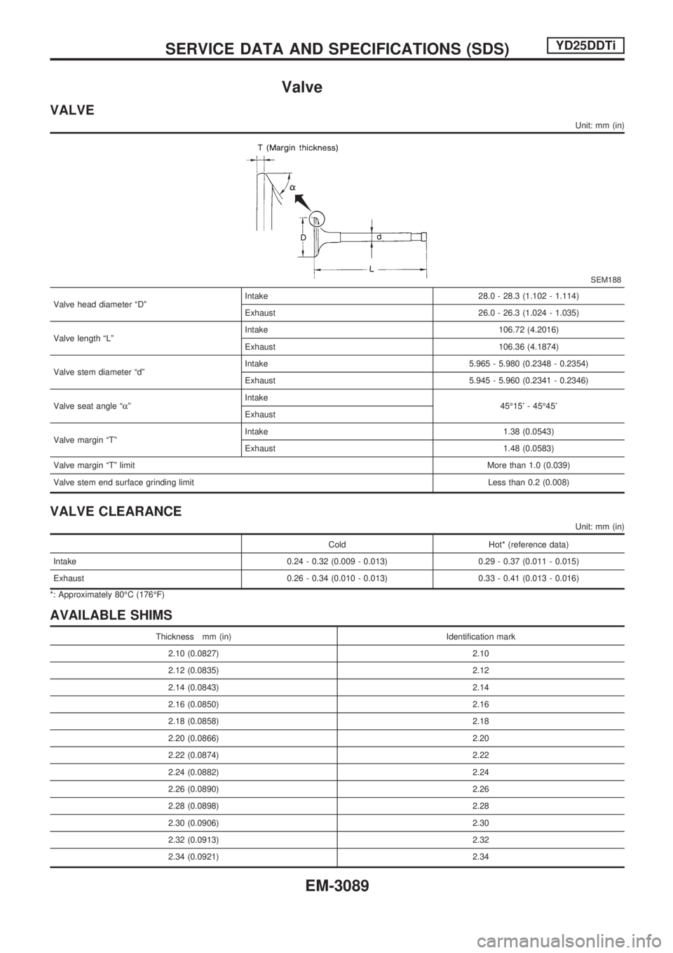
VALVE
Unit: mm (in)
SEM188
Valve head diameter ªDºIntake 28.0 - 28.3 (1.102 - 1.114)
Exhaust 26.0 - 26.3 (1.024 - 1.035)
Valve length ªLºIntake 106.72 (4.2016)
Exhaust 106.36 (4.1874)
Valve stem diameter ªdºIntake 5.965 - 5.980 (0.2348 - 0.2354)
Exhaust 5.945 - 5.960 (0.2341 - 0.2346)
Valve seat angle ªaºIntake
45É15¢- 45É45¢
Exhaust
Valve margin ªTºIntake 1.38 (0.0543)
Exhaust 1.48 (0.0583)
Valve margin ªTº limitMore than 1.0 (0.039)
Valve stem end surface grinding limitLess than 0.2 (0.008)
VALVE CLEARANCE
Unit: mm (in)
Cold Hot* (reference data)
Intake 0.24 - 0.32 (0.009 - 0.013) 0.29 - 0.37 (0.011 - 0.015)
Exhaust 0.26 - 0.34 (0.010 - 0.013) 0.33 - 0.41 (0.013 - 0.016)
*: Approximately 80ÉC (176ÉF)
AVAILABLE SHIMS
Thickness mm (in) Identification mark
2.10 (0.0827) 2.10
2.12 (0.0835) 2.12
2.14 (0.0843) 2.14
2.16 (0.0850) 2.16
2.18 (0.0858) 2.18
2.20 (0.0866) 2.20
2.22 (0.0874) 2.22
2.24 (0.0882) 2.24
2.26 (0.0890) 2.26
2.28 (0.0898) 2.28
2.30 (0.0906) 2.30
2.32 (0.0913) 2.32
2.34 (0.0921) 2.34
SERVICE DATA AND SPECIFICATIONS (SDS)YD25DDTi
EM-3089
Page 968 of 1306
VALVE GUIDE
Unit: mm (in)
JEM156G
Standard Service
Valve guide Outer diameter 10.023 - 10.034 (0.3946 - 0.3950) 10.223 - 10.234 (0.4025 - 0.4029)
Valve guide Inner diameter (Finished size) 6.000 - 6.018 (0.2362 - 0.2369)
Cylinder head valve guide hole diameter 9.975 - 9.996 (0.3927 - 0.3935) 10.175 - 10.196 (0.4006 - 0.4014)
Interference fit of valve guide 0.027 - 0.059 (0.0011 - 0.0023)
Standard Limit
Stem to guide clearanceIntake 0.020 - 0.053 (0.0008 - 0.0021) 0.08 (0.0031)
Exhaust 0.040 - 0.073 (0.0016 - 0.0029) 0.1 (0.004)
Valve deflection limit0.15 (0.0059)
Projection length10.4 - 10.6 (0.409 - 0.417)
SERVICE DATA AND SPECIFICATIONS (SDS)YD25DDTi
Valve (Cont'd)
EM-3091
Page 1014 of 1306
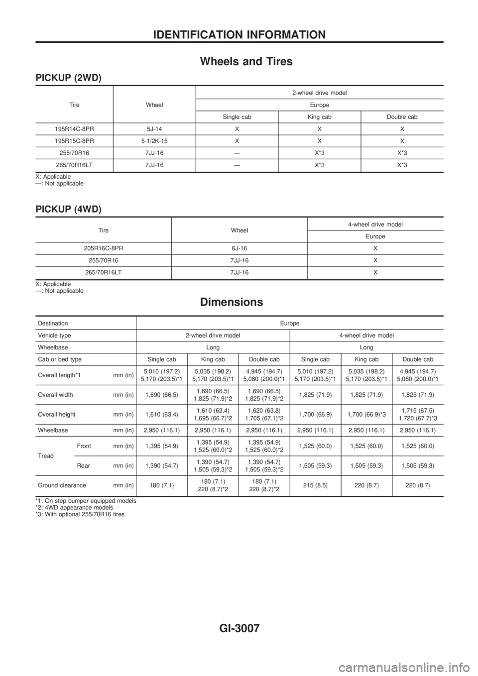
Wheels and Tires
PICKUP (2WD)
Tire Wheel2-wheel drive model
Europe
Single cab King cab Double cab
195R14C-8PR 5J-14 X X X
195R15C-8PR 5-1/2K-15 X X X
255/70R16 7JJ-16 Ð X*3 X*3
265/70R16LT 7JJ-16 Ð X*3 X*3
X: Applicable
Ð: Not applicable
PICKUP (4WD)
Tire Wheel4-wheel drive model
Europe
205R16C-8PR 6J-16 X
255/70R16 7JJ-16 X
265/70R16LT 7JJ-16 X
X: Applicable
Ð: Not applicable
Dimensions
DestinationEurope
Vehicle type 2-wheel drive model 4-wheel drive model
Wheelbase Long Long
Cab or bed type Single cab King cab Double cab Single cab King cab Double cab
Overall length*1 mm (in)5,010 (197.2)
5,170 (203.5)*15,035 (198.2)
5,170 (203.5)*14,945 (194.7)
5,080 (200.0)*15,010 (197.2)
5,170 (203.5)*15,035 (198.2)
5,170 (203.5)*14,945 (194.7)
5,080 (200.0)*1
Overall width mm (in) 1,690 (66.5)1,690 (66.5)
1,825 (71.9)*21,690 (66.5)
1,825 (71.9)*21,825 (71.9) 1,825 (71.9) 1,825 (71.9)
Overall height mm (in) 1,610 (63.4)1,610 (63.4)
1,695 (66.7)*21,620 (63.8)
1,705 (67.1)*21,700 (66.9) 1,700 (66.9)*31,715 (67.5)
1,720 (67.7)*3
Wheelbase mm (in) 2,950 (116.1) 2,950 (116.1) 2,950 (116.1) 2,950 (116.1) 2,950 (116.1) 2,950 (116.1)
TreadFront mm (in) 1,395 (54.9)1,395 (54.9)
1,525 (60.0)*21,395 (54.9)
1,525 (60.0)*21,525 (60.0) 1,525 (60.0) 1,525 (60.0)
Rear mm (in) 1,390 (54.7)1,390 (54.7)
1,505 (59.3)*21,390 (54.7)
1,505 (59.3)*21,505 (59.3) 1,505 (59.3) 1,505 (59.3)
Ground clearance mm (in) 180 (7.1)180 (7.1)
220 (8.7)*2180 (7.1)
220 (8.7)*2215 (8.5) 220 (8.7) 220 (8.7)
*1: On step bumper equipped models
*2: 4WD appearance models
*3: With optional 255/70R16 tires
IDENTIFICATION INFORMATION
GI-3007
Page 1110 of 1306
Propeller Shaft
GENERAL SPECIFICATIONS
2WD models
Applied modelYD25DDTi
Without ABS
(Except 16-inch wheel)Without ABS
(16-inch wheel)With ABS
Propeller shaft model3S80B
Number of joints3
Coupling type with transmission Sleeve type
Types of journal bearing Solid type (disassembly type)
Shaft length (Spider to spider)
mm (in)1st 642 (25.28) 667 (26.26) 642 (25.28)
2nd 1,005 (39.57) 984 (38.74) 979 (38.54)
Shaft outer diameter
mm (in)1st 65 (2.56) 75 (2.95) 65 (2.56)
2nd 65 (2.56) 75 (2.95) 65 (2.56)
4WD models
Applied model YD25DDTi YD25DDTi
Location Front Rear
Propeller shaft model 2F71H 3S80B
Number of joints 2 3
Coupling type with transmission Flange type Sleeve type
Types of journal bearing Solid type (disassembly type)
Shaft length (Spider to spider)
mm (in)1st 565 (22.24) 372 (14.65)
2nd Ð 872 (34.33)
Shaft outer diameter
mm (in)1st 50.8 (2.000) 65.0 (2.559)
2nd Ð 65.0 (2.559)
SERVICE DATA AND SPECIFICATIONS (SDS)
PD-3002
Page 1128 of 1306
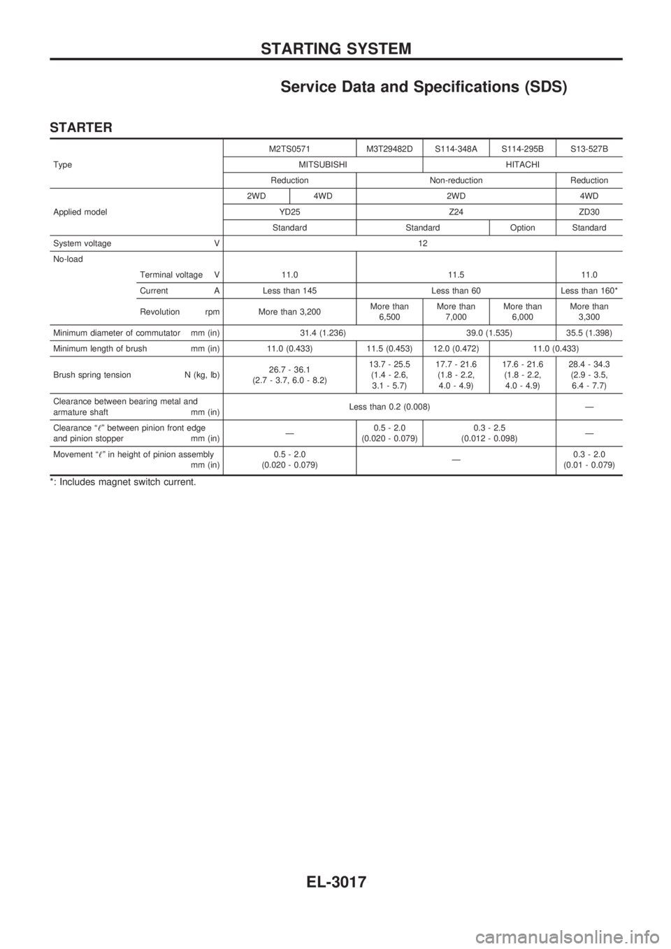
Service Data and Specifications (SDS)
STARTER
TypeM2TS0571 M3T29482D S114-348A S114-295B S13-527B
MITSUBISHI HITACHI
Reduction Non-reduction Reduction
Applied model2WD 4WD 2WD 4WD
YD25 Z24 ZD30
Standard Standard Option Standard
System voltage V 12
No-load
Terminal voltage V 11.0 11.5 11.0
Current A Less than 145 Less than 60 Less than 160*
Revolution rpm More than 3,200More than
6,500More than
7,000More than
6,000More than
3,300
Minimum diameter of commutator mm (in) 31.4 (1.236) 39.0 (1.535) 35.5 (1.398)
Minimum length of brush mm (in) 11.0 (0.433) 11.5 (0.453) 12.0 (0.472) 11.0 (0.433)
Brush spring tension N (kg, lb)26.7 - 36.1
(2.7 - 3.7, 6.0 - 8.2)13.7 - 25.5
(1.4 - 2.6,
3.1 - 5.7)17.7 - 21.6
(1.8 - 2.2,
4.0 - 4.9)17.6 - 21.6
(1.8 - 2.2,
4.0 - 4.9)28.4 - 34.3
(2.9 - 3.5,
6.4 - 7.7)
Clearance between bearing metal and
armature shaft mm (in)Less than 0.2 (0.008) Ð
Clearance ª!º between pinion front edge
and pinion stopper mm (in)Ð0.5 - 2.0
(0.020 - 0.079)0.3 - 2.5
(0.012 - 0.098)Ð
Movement ª!º in height of pinion assembly
mm (in)0.5 - 2.0
(0.020 - 0.079)Ð0.3 - 2.0
(0.01 - 0.079)
*: Includes magnet switch current.
STARTING SYSTEM
EL-3017
Page 1133 of 1306
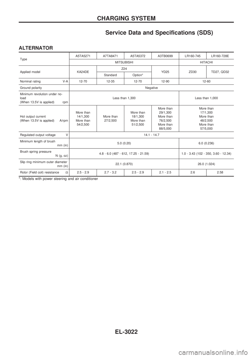
Service Data and Specifications (SDS)
ALTERNATOR
TypeA5TA5271 A7TA8471 A5TA5372 A3TB0699 LR160-745 LR160-728E
MITSUBISHI HITACHI
Applied model KA24DEZ24
YD25 ZD30 TD27, QD32
Standard Option*
Nominal rating V-A 12-70 12-35 12-70 12-90 12-60
Ground polarityNegative
Minimum revolution under no-
load
(When 13.5V is applied) rpmLess than 1,300 Less than 1,000
Hot output current
(When 13.5V is applied) A/rpmMore than
14/1,300
More than
54/2,500More than
27/2,500More than
18/1,300
More than
51/2,500More than
29/1,300
More than
76/2,500
More than
88/5,000More than
17/1,300
More than
48/2,500
More than
57/5,000
Regulated output voltage V 14.1 - 14.7
Minimum length of brush
mm (in)5.0 (0.20) 6.0 (0.236)
Brush spring pressure
N (g, oz)4.8 - 6.0 (487 - 612, 17.25 - 21.59) 1.0 - 3.43 (102 - 350, 3.60 - 12.34)
Slip ring minimum outer diameter
mm (in)22.1 (0.870) 26.0 (1.024)
Rotor (Field coil) resistanceW2.5 - 2.9 2.7 - 3.2 2.5 - 2.9 2.1 - 2.5 2.6 2.58
*: Models with power steering and air conditioner
CHARGING SYSTEM
EL-3022