Page 621 of 1306
Diagnostic Procedure
1 CHECK ECM POWER SUPPLY CIRCUIT
1. Turn ignition switch ªOFFº.
2. Disconnect ECM relay.
SEC950C
3. Check voltage between ECM terminals 2, 7 and ground with CONSULT-II or tester.
SEC241D
OK or NG
OKcGO TO 3.
NGcGO TO 2.
2 DETECT MALFUNCTIONING PART
Check the following.
+20A fuse
+Harness for open and short between ECM relay and battery
cRepair open circuit or short to ground or short to power in harness or connectors.
3 CHECK ECM INPUT SIGNAL CIRCUIT FOR OPEN AND SHORT
1. Turn ignition switch ªOFFº.
2. Disconnect ECM harness connector.
3. Check harness continuity between ECM terminals 56, 61 and ECM relay terminal 6. Refer to Wiring Diagram.
Continuity should exist.
4. Also check harness for short to ground and short to power.
OK or NG
OKcGO TO 5.
NGcGO TO 4.
DTC 0902 ECM RLYYD25DDTi
EC-3596
Page 623 of 1306
Description
The ECM consists of a microcomputer and connectors for signal
input and output and for power supply. The unit controls the
engine.
On Board Diagnosis Logic
Malfunction is detected when ... Check Items (Possible Cause)
+ECM input signal processing function is malfunctioning.+ECM
(ECCS-D control module)
DTC Confirmation Procedure
WITH CONSULT-II
1) Turn ignition switch ªONº.
2) Select ªDATA MONITORº mode with CONSULT-II.
3) Turn ignition switch ªOFFº, wait at least 20 seconds and then
turn ªONº.
4) If DTC is detected, go to ªDiagnostic Procedureº, EC-3600.
WITHOUT CONSULT-II
1) Turn ignition switch ªONº and wait at least 2 seconds.
2) Turn ignition switch ªOFFº, wait at least 20 seconds and then
turn ªONº.
3) Perform ªDiagnostic Test Mode II (Self-diagnostic results)º
with ECM.
4) If DTC is detected, go to ªDiagnostic Procedureº, EC-3600.
SEC220B
SEF817Y
DTC 0903 ECM 15YD25DDTi
EC-3598
Page 628 of 1306

Diagnostic Procedure
1 CHECK CHARGE AIR PRESSURE SENSOR POWER SUPPLY CIRCUIT
1. Stop engine.
2. Disconnect charge air pressure sensor harness connector.
SEC234D
3. Turn ignition switch ªONº.
4. Check voltage between charge air pressure sensor terminal 1 and ground with CONSULT-II or tester.
SEF306Z
OK or NG
OKcGO TO 2.
NGcRepair harness or connectors.
2 CHECK CHARGE AIR PRESSURE SENSOR GROUND CIRCUIT FOR OPEN AND SHORT
1. Turn ignition switch ªOFFº.
2. Check harness continuity between charge air pressure sensor terminal 3 and engine ground. Refer to Wiring Diagram.
Continuity should exist.
3. Also check harness for short to power.
OK or NG
OKcGO TO 3.
NGcRepair open circuit or short to ground or short to power in harness or connectors.
3 CHECK CHARGE AIR PRESSURE SENSOR INPUT SIGNAL CIRCUIT FOR OPEN AND SHORT
1. Disconnect ECM harness connector.
2. Check harness continuity between ECM terminal 46 and charge air pressure sensor terminal 2. Refer to Wiring Diagram.
Continuity should exist.
3. Also check harness for short to ground and short to power.
OK or NG
OKcGO TO 4.
NGcRepair open circuit or short to ground or short to power in harness or connectors.
DTC 0905 TURBO PRESSUREYD25DDTi
EC-3603
Page 631 of 1306

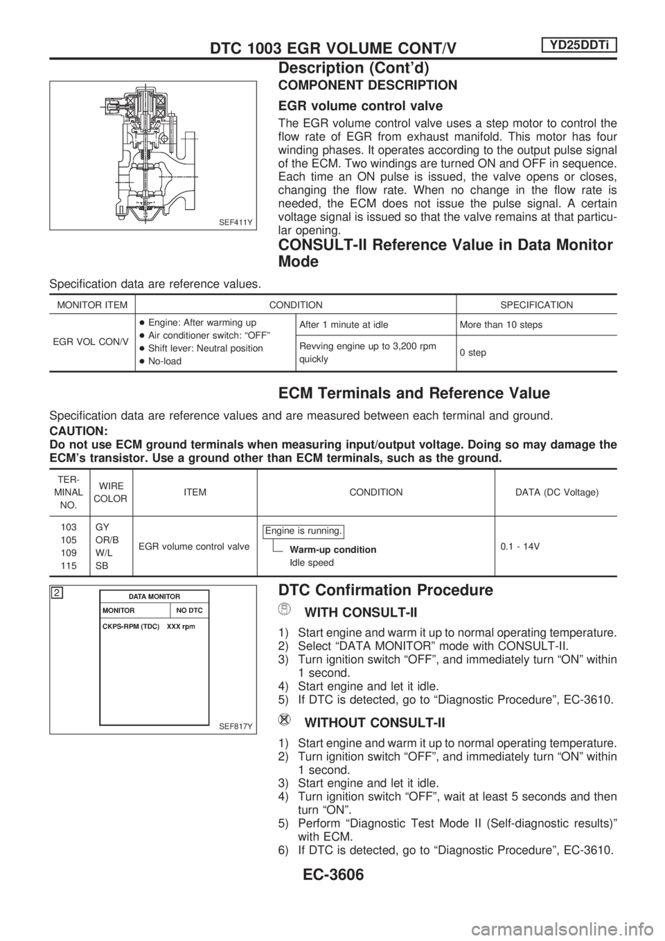
COMPONENT DESCRIPTION
EGR volume control valve
The EGR volume control valve uses a step motor to control the
flow rate of EGR from exhaust manifold. This motor has four
winding phases. It operates according to the output pulse signal
of the ECM. Two windings are turned ON and OFF in sequence.
Each time an ON pulse is issued, the valve opens or closes,
changing the flow rate. When no change in the flow rate is
needed, the ECM does not issue the pulse signal. A certain
voltage signal is issued so that the valve remains at that particu-
lar opening.
CONSULT-II Reference Value in Data Monitor
Mode
Specification data are reference values.
MONITOR ITEM CONDITION SPECIFICATION
EGR VOL CON/V+Engine: After warming up
+Air conditioner switch: ªOFFº
+Shift lever: Neutral position
+No-loadAfter 1 minute at idle More than 10 steps
Revving engine up to 3,200 rpm
quickly0 step
ECM Terminals and Reference Value
Specification data are reference values and are measured between each terminal and ground.
CAUTION:
Do not use ECM ground terminals when measuring input/output voltage. Doing so may damage the
ECM's transistor. Use a ground other than ECM terminals, such as the ground.
TER-
MINAL
NO.WIRE
COLORITEM CONDITION DATA (DC Voltage)
103
105
109
115GY
OR/B
W/L
SBEGR volume control valveEngine is running.
Warm-up condition
Idle speed0.1 - 14V
DTC Confirmation Procedure
WITH CONSULT-II
1) Start engine and warm it up to normal operating temperature.
2) Select ªDATA MONITORº mode with CONSULT-II.
3) Turn ignition switch ªOFFº, and immediately turn ªONº within
1 second.
4) Start engine and let it idle.
5) If DTC is detected, go to ªDiagnostic Procedureº, EC-3610.
WITHOUT CONSULT-II
1) Start engine and warm it up to normal operating temperature.
2) Turn ignition switch ªOFFº, and immediately turn ªONº within
1 second.
3) Start engine and let it idle.
4) Turn ignition switch ªOFFº, wait at least 5 seconds and then
turn ªONº.
5) Perform ªDiagnostic Test Mode II (Self-diagnostic results)º
with ECM.
6) If DTC is detected, go to ªDiagnostic Procedureº, EC-3610.
SEF411Y
SEF817Y
DTC 1003 EGR VOLUME CONT/VYD25DDTi
Description (Cont'd)
EC-3606
Page 636 of 1306

5 DETECT MALFUNCTIONING PART
Check the following.
+10A fuse
+Harness for open or short between ECM relay and battery
cRepair open circuit or short to ground or short to power in harness or connectors.
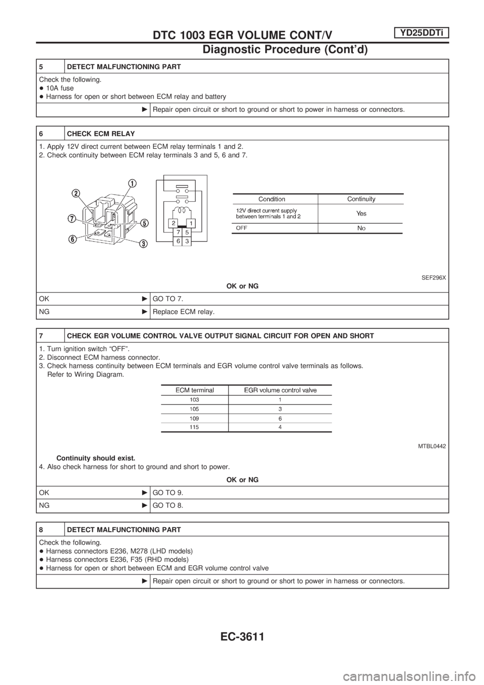
6 CHECK ECM RELAY
1. Apply 12V direct current between ECM relay terminals 1 and 2.
2. Check continuity between ECM relay terminals 3 and 5, 6 and 7.
SEF296X
OK or NG
OKcGO TO 7.
NGcReplace ECM relay.
7 CHECK EGR VOLUME CONTROL VALVE OUTPUT SIGNAL CIRCUIT FOR OPEN AND SHORT
1. Turn ignition switch ªOFFº.
2. Disconnect ECM harness connector.
3. Check harness continuity between ECM terminals and EGR volume control valve terminals as follows.
Refer to Wiring Diagram.
MTBL0442
Continuity should exist.
4. Also check harness for short to ground and short to power.
OK or NG
OKcGO TO 9.
NGcGO TO 8.
8 DETECT MALFUNCTIONING PART
Check the following.
+Harness connectors E236, M278 (LHD models)
+Harness connectors E236, F35 (RHD models)
+Harness for open or short between ECM and EGR volume control valve
cRepair open circuit or short to ground or short to power in harness or connectors.
DTC 1003 EGR VOLUME CONT/VYD25DDTi
Diagnostic Procedure (Cont'd)
EC-3611
Page 646 of 1306

Description
SYSTEM DESCRIPTION
Sensor Input Signal to ECMECM
FunctionActuator
Crankshaft position
sensor (TDC)Engine speed
Glow
controlGlow lamp,
Glow relay
¯
Glow plugs Engine coolant tem-
perature sensorEngine coolant tem-
perature
When engine coolant temperature is more than approximately
75ÉC (167ÉF), the glow relay turns off, inactivating the quick-glow
control until coolant temperature drops below approximately
55ÉC (131ÉF).
When coolant temperature is lower than approximately 75ÉC
(167ÉF):
+Ignition switch ON
After ignition switch has turned to ON, the glow relay turns
ON for a certain period of time in relation to engine coolant
temperature, allowing current to flow through glow plug.
+Cranking
The glow relay turns ON, allowing current to flow through
glow plug.
+Starting
After engine has started, current continues to flow through
glow plug (after-glow mode) for a certain period in relation to
engine coolant temperature.
When engine speed exceeds approximately 4,800 rpm, cur-
rent flow through glow plug is interrupted.
The glow indicator lamp turns ON for a certain period of time in
relation to engine coolant temperature at the time glow relay is
turned ON.
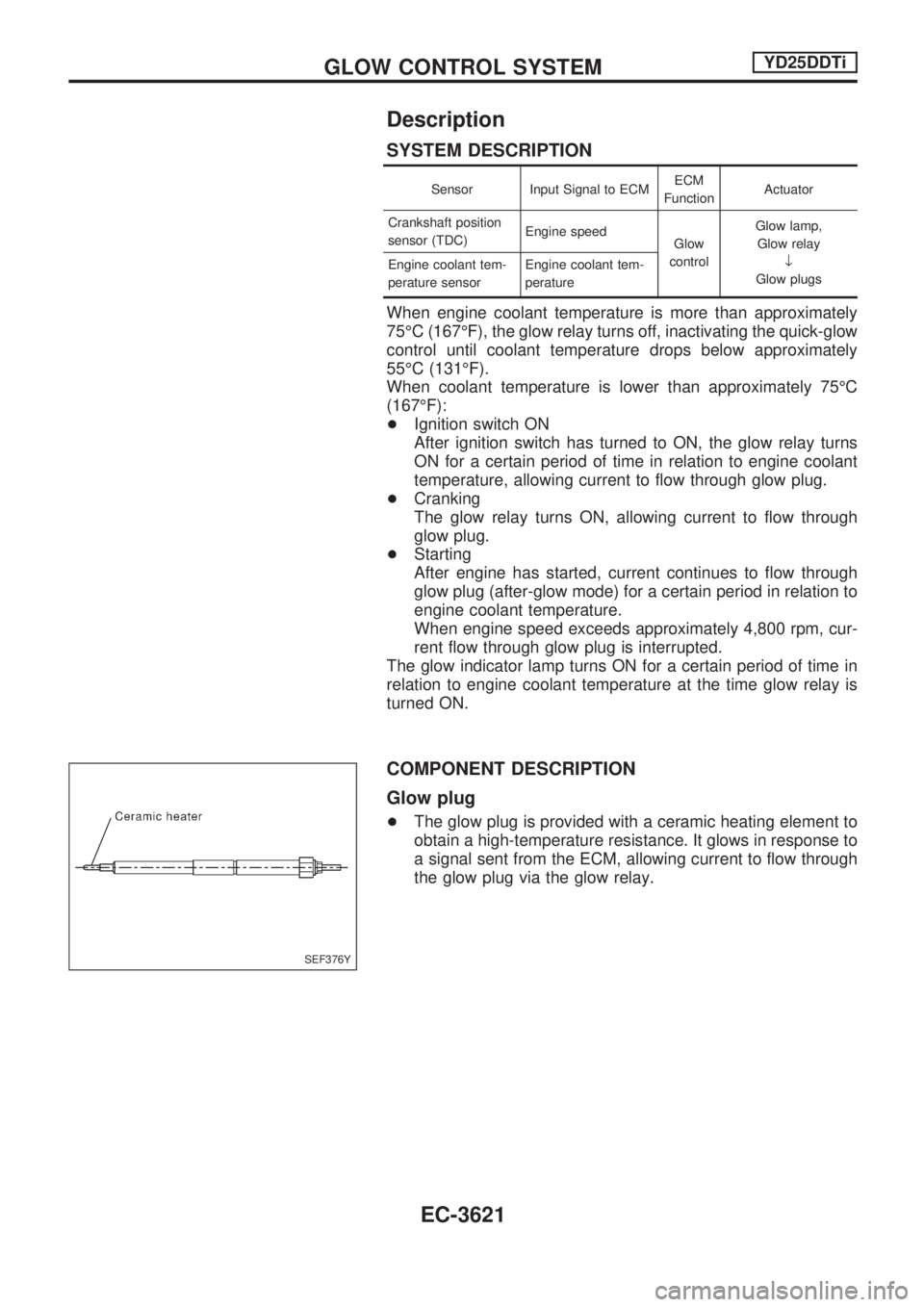
COMPONENT DESCRIPTION
Glow plug
+The glow plug is provided with a ceramic heating element to
obtain a high-temperature resistance. It glows in response to
a signal sent from the ECM, allowing current to flow through
the glow plug via the glow relay.
SEF376Y
GLOW CONTROL SYSTEMYD25DDTi
EC-3621
Page 651 of 1306

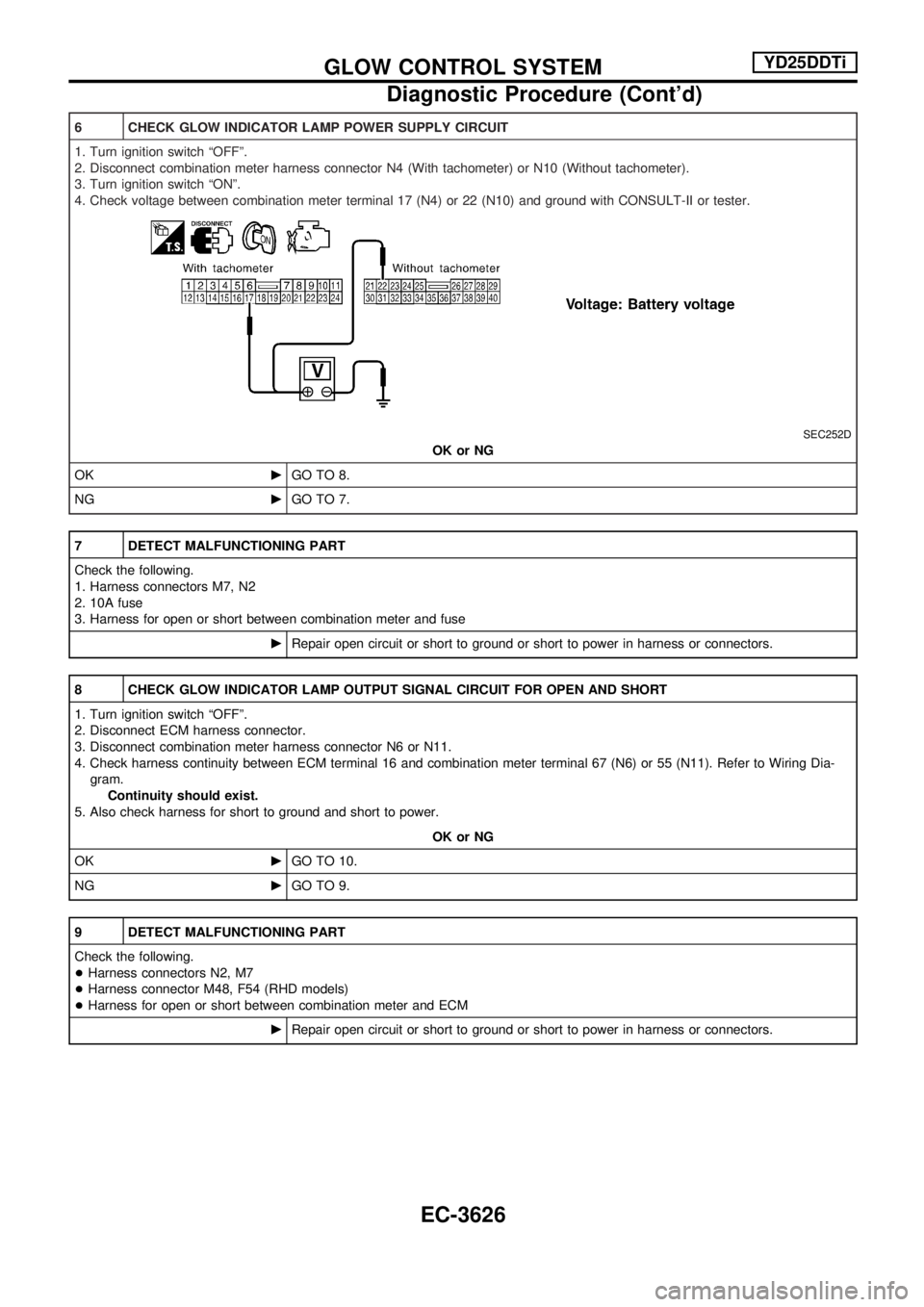
6 CHECK GLOW INDICATOR LAMP POWER SUPPLY CIRCUIT
1. Turn ignition switch ªOFFº.
2. Disconnect combination meter harness connector N4 (With tachometer) or N10 (Without tachometer).
3. Turn ignition switch ªONº.
4. Check voltage between combination meter terminal 17 (N4) or 22 (N10) and ground with CONSULT-II or tester.
SEC252D
OK or NG
OKcGO TO 8.
NGcGO TO 7.
7 DETECT MALFUNCTIONING PART
Check the following.
1. Harness connectors M7, N2
2. 10A fuse
3. Harness for open or short between combination meter and fuse
cRepair open circuit or short to ground or short to power in harness or connectors.
8 CHECK GLOW INDICATOR LAMP OUTPUT SIGNAL CIRCUIT FOR OPEN AND SHORT
1. Turn ignition switch ªOFFº.
2. Disconnect ECM harness connector.
3. Disconnect combination meter harness connector N6 or N11.
4. Check harness continuity between ECM terminal 16 and combination meter terminal 67 (N6) or 55 (N11). Refer to Wiring Dia-
gram.
Continuity should exist.
5. Also check harness for short to ground and short to power.
OK or NG
OKcGO TO 10.
NGcGO TO 9.
9 DETECT MALFUNCTIONING PART
Check the following.
+Harness connectors N2, M7
+Harness connector M48, F54 (RHD models)
+Harness for open or short between combination meter and ECM
cRepair open circuit or short to ground or short to power in harness or connectors.
GLOW CONTROL SYSTEMYD25DDTi
Diagnostic Procedure (Cont'd)
EC-3626
Page 656 of 1306
Diagnostic Procedure
1 CHECK START SIGNAL OVERALL FUNCTION
With CONSULT-II
1. Turn ignition switch ªONº.
2. Check ªSTART SIGNALº in ªDATA MONITORº mode with CONSULT-II under the following conditions.
SEC254D
Without CONSULT-II
Check voltage between ECM terminal 20 and ground under the following conditions.
SEF415Y
OK or NG
OKcINSPECTION END
NGcGO TO 2.
2 CHECK START SIGNAL INPUT SIGNAL CIRCUIT
1. Turn ignition switch ªOFFº.
2. Disconnect ECM harness connector and ignition switch harness connector.
3. Check harness continuity between ECM terminal 20 and ignition switch terminal 6. Refer to Wiring Diagram.
Continuity should exist.
4. Also check harness for short to ground and short to power.
OK or NG
OKcGO TO 4.
NGcGO TO 3.
START SIGNALYD25DDTi
EC-3631