2001 NISSAN PICK-UP turn signal
[x] Cancel search: turn signalPage 806 of 1306
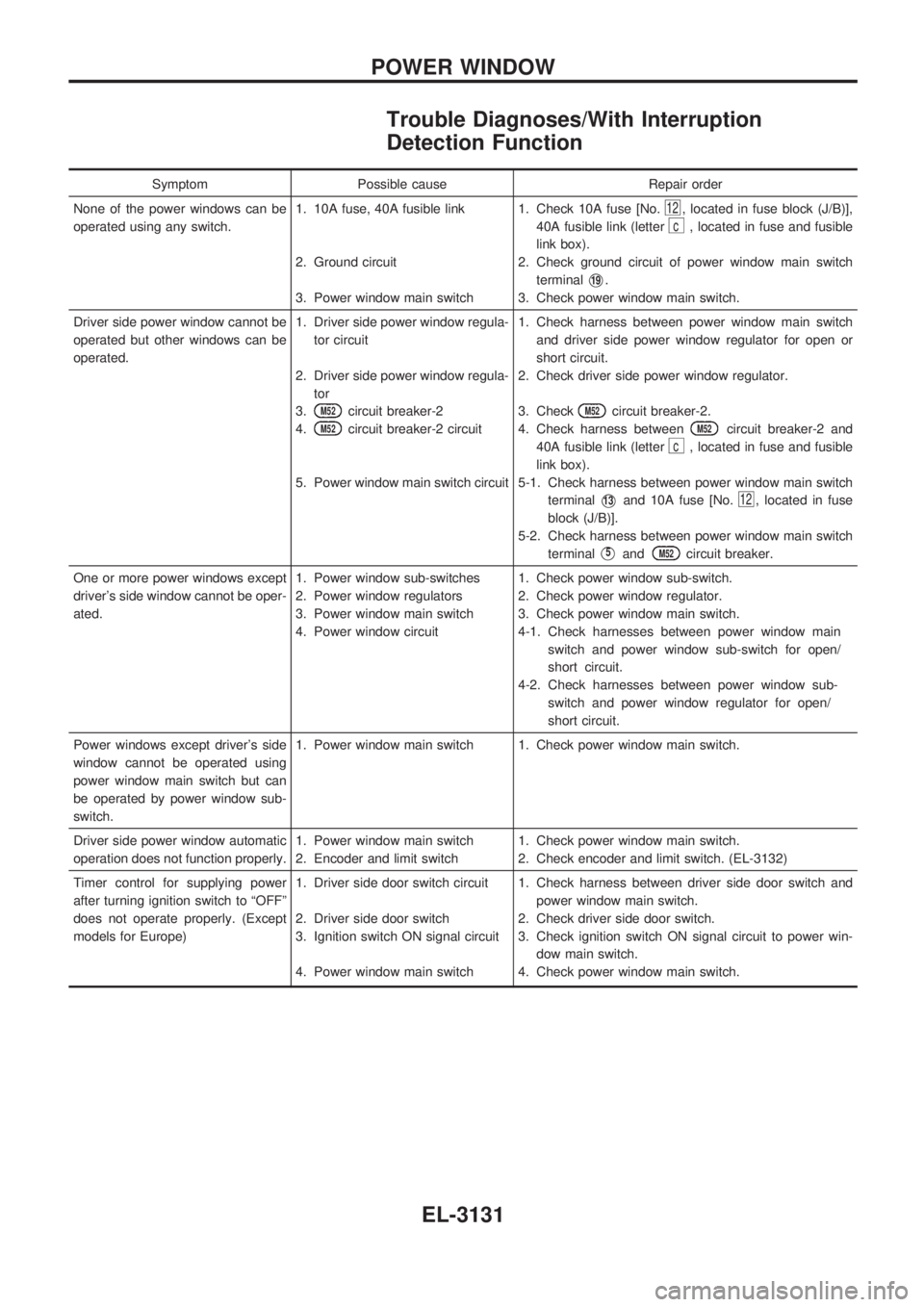
Trouble Diagnoses/With Interruption
Detection Function
Symptom Possible cause Repair order
None of the power windows can be
operated using any switch.1. 10A fuse, 40A fusible link
2. Ground circuit
3. Power window main switch1. Check 10A fuse [No.
12, located in fuse block (J/B)],
40A fusible link (letter
c, located in fuse and fusible
link box).
2. Check ground circuit of power window main switch
terminal
V19.
3. Check power window main switch.
Driver side power window cannot be
operated but other windows can be
operated.1. Driver side power window regula-
tor circuit
2. Driver side power window regula-
tor
3.
M52circuit breaker-2
4.
M52circuit breaker-2 circuit
5. Power window main switch circuit1. Check harness between power window main switch
and driver side power window regulator for open or
short circuit.
2. Check driver side power window regulator.
3. Check
M52circuit breaker-2.
4. Check harness between
M52circuit breaker-2 and
40A fusible link (letter
c, located in fuse and fusible
link box).
5-1. Check harness between power window main switch
terminal
V13and 10A fuse [No.12, located in fuse
block (J/B)].
5-2. Check harness between power window main switch
terminal
V5andM52circuit breaker.
One or more power windows except
driver's side window cannot be oper-
ated.1. Power window sub-switches
2. Power window regulators
3. Power window main switch
4. Power window circuit1. Check power window sub-switch.
2. Check power window regulator.
3. Check power window main switch.
4-1. Check harnesses between power window main
switch and power window sub-switch for open/
short circuit.
4-2. Check harnesses between power window sub-
switch and power window regulator for open/
short circuit.
Power windows except driver's side
window cannot be operated using
power window main switch but can
be operated by power window sub-
switch.1. Power window main switch 1. Check power window main switch.
Driver side power window automatic
operation does not function properly.1. Power window main switch
2. Encoder and limit switch1. Check power window main switch.
2. Check encoder and limit switch. (EL-3132)
Timer control for supplying power
after turning ignition switch to ªOFFº
does not operate properly. (Except
models for Europe)1. Driver side door switch circuit
2. Driver side door switch
3. Ignition switch ON signal circuit
4. Power window main switch1. Check harness between driver side door switch and
power window main switch.
2. Check driver side door switch.
3. Check ignition switch ON signal circuit to power win-
dow main switch.
4. Check power window main switch.
POWER WINDOW
EL-3131
Page 814 of 1306
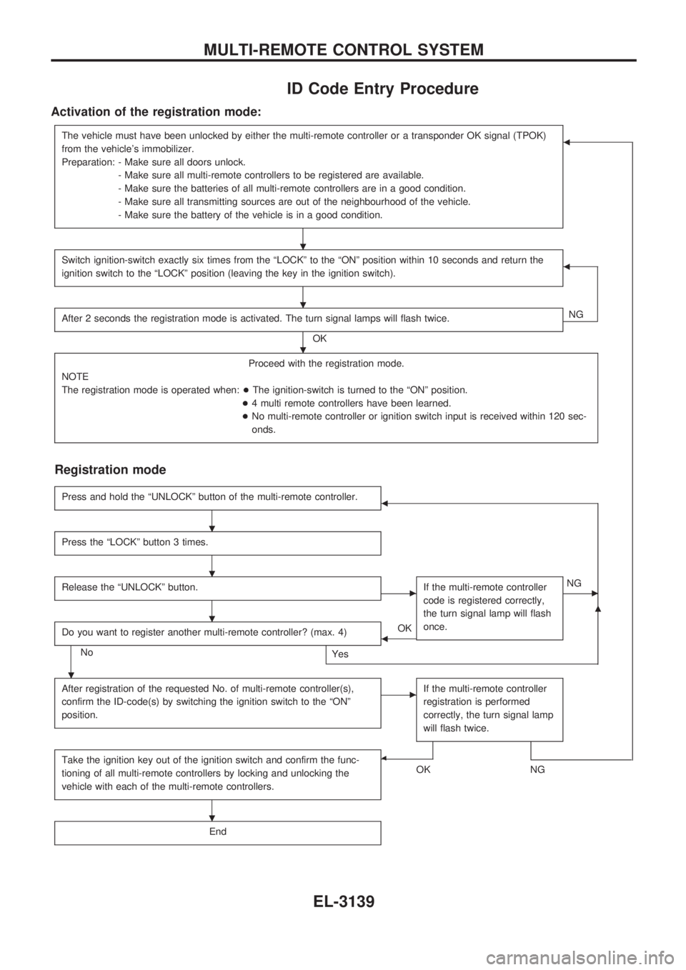
ID Code Entry Procedure
Activation of the registration mode:
The vehicle must have been unlocked by either the multi-remote controller or a transponder OK signal (TPOK)
from the vehicle's immobilizer.
Preparation: - Make sure all doors unlock.
- Make sure all multi-remote controllers to be registered are available.
- Make sure the batteries of all multi-remote controllers are in a good condition.
- Make sure all transmitting sources are out of the neighbourhood of the vehicle.
- Make sure the battery of the vehicle is in a good condition.b
Switch ignition-switch exactly six times from the ªLOCKº to the ªONº position within 10 seconds and return the
ignition switch to the ªLOCKº position (leaving the key in the ignition switch).b
After 2 seconds the registration mode is activated. The turn signal lamps will flash twice.
OKNG
Proceed with the registration mode.
NOTE
The registration mode is operated when:+The ignition-switch is turned to the ªONº position.
+4 multi remote controllers have been learned.
+No multi-remote controller or ignition switch input is received within 120 sec-
onds.
Registration mode
Press and hold the ªUNLOCKº button of the multi-remote controller.b
Press the ªLOCKº button 3 times.
Release the ªUNLOCKº button.cIf the multi-remote controller
code is registered correctly,
the turn signal lamp will flash
once.cNG
Do you want to register another multi-remote controller? (max. 4)
No
Yes
bOK
m
After registration of the requested No. of multi-remote controller(s),
confirm the ID-code(s) by switching the ignition switch to the ªONº
position.cIf the multi-remote controller
registration is performed
correctly, the turn signal lamp
will flash twice.
Take the ignition key out of the ignition switch and confirm the func-
tioning of all multi-remote controllers by locking and unlocking the
vehicle with each of the multi-remote controllers.b
OKNG
End
.
.
.
.
.
.
.
.
MULTI-REMOTE CONTROL SYSTEM
EL-3139
Page 829 of 1306
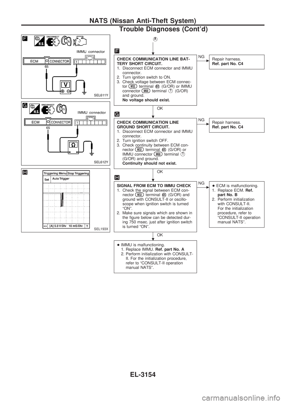
VA
CHECK COMMUNICATION LINE BAT-
TERY SHORT CIRCUIT.
1. Disconnect ECM connector and IMMU
connector.
2. Turn ignition switch to ON.
3. Check voltage between ECM connec-
tor
M32terminalV65(G/OR) or IMMU
connectorM68terminalV1(G/OR)
and ground.
No voltage should exist.
OK
cNG
Repair harness.
Ref. part No. C4
CHECK COMMUNICATION LINE
GROUND SHORT CIRCUIT.
1. Disconnect ECM connector and IMMU
connector.
2. Turn ignition switch OFF.
3. Check continuity between ECM con-
nector
M32terminalV65(G/OR) or
IMMU connectorM68terminalV1
(G/OR) and ground.
Continuity should not exist.
OK
cNG
Repair harness.
Ref. part No. C4
SIGNAL FROM ECM TO IMMU CHECK
1. Check the signal between ECM con-
nector
M32terminalV65(G/OR) and
ground with CONSULT-II or oscillo-
scope when ignition switch is turned
ªONº.
2. Make sure signals which are shown in
the figure below can be detected dur-
ing 750 msec. just after ignition switch
is turned ªONº.
OK
cNG
+ECM is malfunctioning.
1. Replace ECM.Ref.
part No. B
2. Perform initialization
with CONSULT-II.
For the initialization
procedure, refer to
ªCONSULT-II operation
manual NATSº.
+IMMU is malfunctioning.
1. Replace IMMU.Ref. part No. A
2. Perform initialization with CONSULT-
II. For the initialization procedure,
refer to ªCONSULT-II operation
manual NATSº.
SEL611Y
SEL612Y
SEL193X
.
.
.
.
NATS (Nissan Anti-Theft System)
Trouble Diagnoses (Cont'd)
EL-3154
Page 870 of 1306
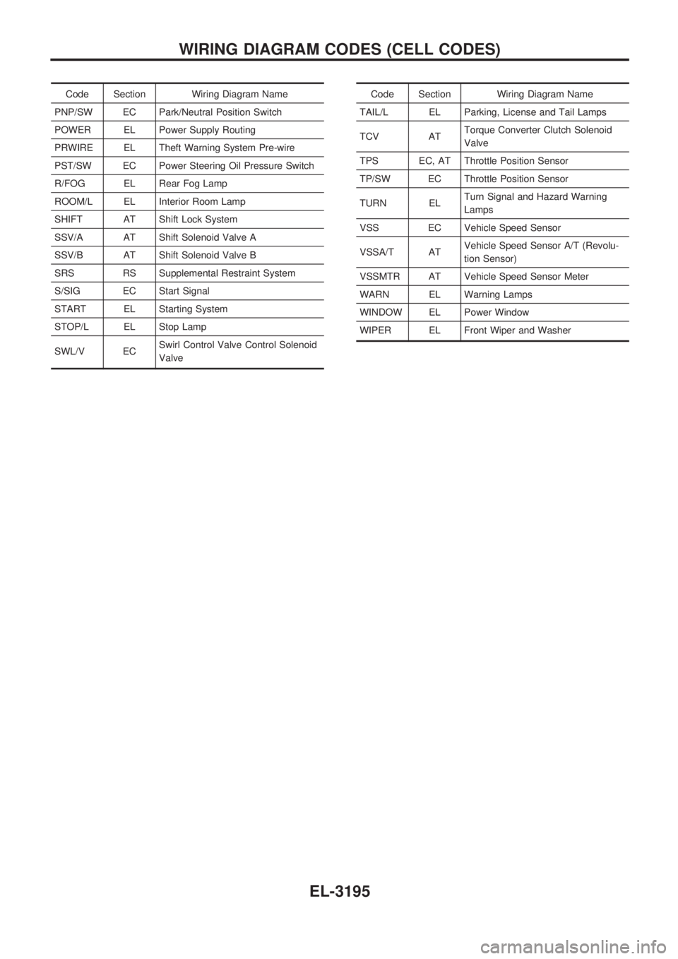
Code Section Wiring Diagram Name
PNP/SW EC Park/Neutral Position Switch
POWER EL Power Supply Routing
PRWIRE EL Theft Warning System Pre-wire
PST/SW EC Power Steering Oil Pressure Switch
R/FOG EL Rear Fog Lamp
ROOM/L EL Interior Room Lamp
SHIFT AT Shift Lock System
SSV/A AT Shift Solenoid Valve A
SSV/B AT Shift Solenoid Valve B
SRS RS Supplemental Restraint System
S/SIG EC Start Signal
START EL Starting System
STOP/L EL Stop Lamp
SWL/V ECSwirl Control Valve Control Solenoid
ValveCode Section Wiring Diagram Name
TAIL/L EL Parking, License and Tail Lamps
TCV ATTorque Converter Clutch Solenoid
Valve
TPS EC, AT Throttle Position Sensor
TP/SW EC Throttle Position Sensor
TURN ELTurn Signal and Hazard Warning
Lamps
VSS EC Vehicle Speed Sensor
VSSA/T ATVehicle Speed Sensor A/T (Revolu-
tion Sensor)
VSSMTR AT Vehicle Speed Sensor Meter
WARN EL Warning Lamps
WINDOW EL Power Window
WIPER EL Front Wiper and Washer
WIRING DIAGRAM CODES (CELL CODES)
EL-3195
Page 1065 of 1306
S
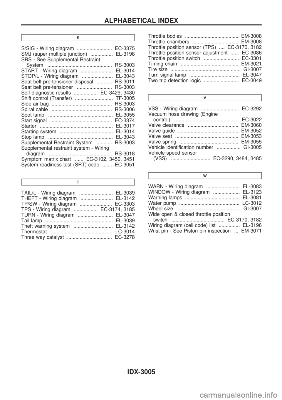
S/SIG - Wiring diagram ......................... EC-3375
SMJ (super multiple junction) ................ EL-3198
SRS - See Supplemental Restraint
System .............................................. RS-3003
START - Wiring diagram ....................... EL-3014
STOP/L - Wiring diagram ...................... EL-3043
Seat belt pre-tensioner disposal ........... RS-3011
Seat belt pre-tensioner ......................... RS-3003
Self-diagnostic results ................. EC-3429, 3430
Shift control (Transfer) ........................... TF-3005
Side air bag ........................................... RS-3003
Spiral cable ........................................... RS-3006
Spot lamp .............................................. EL-3055
Start signal ............................................ EC-3374
Starter .................................................... EL-3017
Starting system ...................................... EL-3014
Stop lamp .............................................. EL-3043
Supplemental Restraint System ........... RS-3003
Supplemental restraint system - Wiring
diagram ............................................. RS-3018
Symptom matrix chart ...... EC-3102, 3450, 3451
System readiness test (SRT) code ....... EC-3051
T
TAIL/L - Wiring diagram ........................ EL-3039
THEFT - Wiring diagram ....................... EL-3142
TP/SW - Wiring diagram ....................... EC-3303
TPS - Wiring diagram ................. EC-3174, 3185
TURN - Wiring diagram ......................... EL-3047
Tail lamp ................................................ EL-3039
Theft warning system ............................ EL-3142
Thermostat ............................................ LC-3014
Three way catalyst ................................ EC-3278Throttle bodies ...................................... EM-3008
Throttle chambers ................................. EM-3008
Throttle position sensor (TPS) .... EC-3170, 3182
Throttle position sensor adjustment ...... EC-3086
Throttle position switch ......................... EC-3301
Timing chain ......................................... EM-3021
Tire size .................................................. GI-3007
Turn signal lamp .................................... EL-3047
Two trip detection logic ......................... EC-3049
V
VSS - Wiring diagram ........................... EC-3292
Vacuum hose drawing (Engine
control) .............................................. EC-3022
Valve clearance .................................... EM-3060
Valve guide ........................................... EM-3052
Valve seat ............................................. EM-3053
Valve spring .......................................... EM-3055
Vehicle identification number ................. GI-3005
Vehicle speed sensor
(VSS) ............................ EC-3290, 3484, 3485
W
WARN - Wiring diagram ........................ EL-3083
WINDOW - Wiring diagram ................... EL-3123
Warning lamps ....................................... EL-3081
Water pump ........................................... LC-3012
Wheel size .............................................. GI-3007
Wide open & closed throttle position
switch ...................................... EC-3170, 3182
Wiring diagram (cell code) list ............... EL-3196
Wrist pin - See Piston pin inspection ... EM-3071
ALPHABETICAL INDEX
IDX-3005
Page 1112 of 1306
ELECTRICAL SYSTEM
SECTION
EL
MODIFICATION NOTICE:
+Wiring diagrams have been changed.
+Combination meter has been changed.
+Headlamp has been changed.
+Headlamp aiming control has been added.
+Headlamp washer has been added.
+A hazard reminder feature has been added to the multi-remote control system.
+NATS (Nissan Anti-Theft System) has been changed.
CONTENTS
PRECAUTIONS................................................... 3004
Supplemental Restraint System (SRS)²AIR
BAG²and²SEAT BELT PRE-TENSIONER².. 3004
POWER SUPPLY ROUTING............................... 3005
Schematic ........................................................ 3005
Wiring Diagram - POWER -............................. 3006
BATTERY............................................................. 3013
Service Data and Specifications (SDS) ........... 3013
STARTING SYSTEM........................................... 3014
Wiring Diagram - START -/M/T Models .......... 3014
Construction ..................................................... 3015
Service Data and Specifications (SDS) ........... 3017
CHARGING SYSTEM.......................................... 3018
Wiring Diagram - CHARGE -/Diesel Engine ... 3018
Wiring Diagram - CHARGE - (KA engine) ...... 3019
Construction ..................................................... 3020
Service Data and Specifications (SDS) ........... 3022
HEADLAMP - Conventional Type -................... 3023
Wiring Diagram - H/LAMP -/LHD Models ........ 3023
Wiring Diagram - H/LAMP -/RHD Models ....... 3025
Bulb Replacement............................................ 3027
Aiming Adjustment ........................................... 3027
Low Beam ........................................................ 3028
HEADLAMP - Daytime Light System -............. 3029
Wiring Diagram - DTRL - ................................. 3029
Bulb Replacement............................................ 3032
Aiming Adjustment ........................................... 3032
HEADLAMP - Dim-dip Lamp System -............. 3033Wiring Diagram - DIMDIP -.............................. 3033
Bulb Replacement............................................ 3036
Aiming Adjustment ........................................... 3036
HEADLAMP - Headlamp Aiming Control -....... 3037
Wiring Diagram - H/AIM - ................................ 3037
PARKING, LICENSE AND TAIL LAMPS........... 3039
Wiring Diagram - TAIL/L -/Except LHD Models
for Europe ........................................................ 3039
Wiring Diagram - TAIL/L -/LHD Models for
Europe.............................................................. 3041
STOP LAMP........................................................ 3043
Wiring Diagram - STOP/L - ............................. 3043
BACK-UP LAMP.................................................. 3044
Wiring Diagram - BACK/L -/M/T Models ......... 3044
REAR FOG LAMP............................................... 3045
Wiring Diagram - R/FOG -/LHD Models .......... 3045
Wiring Diagram - R/FOG -/RHD Models ......... 3046
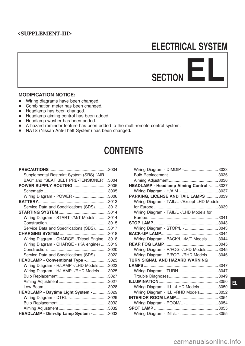
TURN SIGNAL AND HAZARD WARNING
LAMPS................................................................. 3047
Wiring Diagram - TURN - ................................ 3047
Trouble Diagnoses ........................................... 3049
ILLUMINATION.................................................... 3050
Wiring Diagram - ILL -/LHD Models ................ 3050
Wiring Diagram - ILL -/RHD Models................ 3052
INTERIOR ROOM LAMP..................................... 3054
Wiring Diagram - ROOM/L - ............................ 3054
SPOT LAMP........................................................ 3055
Wiring Diagram - INT/L - ................................. 3055
EL
Page 1158 of 1306

Wiring Diagram Ð TURN Ð
GEL385A
TURN SIGNAL AND HAZARD WARNING LAMPS
EL-3047
Page 1159 of 1306

GEL463A
TURN SIGNAL AND HAZARD WARNING LAMPS
Wiring Diagram Ð TURN Ð (Cont'd)
EL-3048