Page 660 of 1306
Diagnostic Procedure
1 CHECK OVERALL FUNCTION
With CONSULT-II
1. Turn ignition switch ªONº.
2. Select ªP/N POSI SWº in ªDATA MONITORº mode with CONSULT-II.
3. Check ªP/N POSI SWº signal under the following conditions.
SEF049Y
Without CONSULT-II
1. Turn ignition switch ªONº.
2. Check voltage between ECM terminal 22 and ground under the following conditions.
SEF419Y
OK or NG
OKcINSPECTION END
NGcGO TO 2.
PARK/NEUTRAL POSITION (PNP) SWITCHYD25DDTi
EC-3635
Page 661 of 1306

2 CHECK PNP SWITCH GROUND CIRCUIT FOR OPEN AND SHORT
1. Turn ignition switch ªOFFº.
2. Disconnect park/neutral position (PNP) switch harness connector.
SEC170D
3. Check harness continuity between PNP switch terminal 2 and body ground. Refer to Wiring Diagram.
Continuity should exist.
4. Also check harness for short to ground and short to power.
OK or NG
OKcGO TO 4.
NGcGO TO 3.
3 DETECT MALFUNCTIONING PART
Check the following.
+Harness connectors E203, E30
+Harness for open or short between PNP switch and body ground
cRepair open circuit or short to ground or short to power in harness or connectors.
4 CHECK PNP SWITCH INPUT SIGNAL CIRCUIT FOR OPEN AND SHORT
1. Disconnect ECM harness connector.
2. Check harness continuity between ECM terminal 22 and PNP switch terminal 1. Refer to Wiring Diagram.
Continuity should exist.
3. Also check harness for short to ground and short to power.
OK or NG
OKcGO TO 6.
NGcGO TO 5.
5 DETECT MALFUNCTIONING PART
Check the following.
+Harness connectors M278, E236 (LHD models)
+Harness connectors F35, E236 (RHD models)
+Harness for open or short between PNP switch and ECM
cRepair open circuit or short to ground or short to power in harness or connectors.
6 CHECK PARK/NEUTRAL POSITION SWITCH
Refer to MT section (ªPOSITION SWITCH CHECKº).
OK or NG
OKcGO TO 7.
NGcReplace park/neutral position switch.
PARK/NEUTRAL POSITION (PNP) SWITCHYD25DDTi
Diagnostic Procedure (Cont'd)
EC-3636
Page 666 of 1306

4 CHECK OVERALL FUNCTION-II
Check the indicator when turning ªONº and ªOFFº the heat up switch.
MTBL1314
OK or NG
OKcINSPECTION END
NGcGO TO 10.
5 CHECK HEAT UP SWITCH POWER SUPPLY CIRCUIT
1. Turn heat up switch ªOFFº.
2. Turn ignition switch ªOFFº.
3. Disconnect heat up switch harness connector.
4. Turn ignition switch ªONº.
5. Check voltage between heat up switch terminal 6 and ground with CONSULT-II or tester.
SEF304Z
OK or NG
OKcGO TO 7.
NGcGO TO 6.
6 DETECT MALFUNCTIONING PART
Check the following.
+Harness connectors N1, M6
+10A fuse
+Harness for open or short between heat up switch and fuse
cRepair open circuit or short to ground or short to power in harness or connectors.
7 CHECK HEAT UP SWITCH INPUT SIGNAL CIRCUIT FOR OPEN OR SHORT
1. Turn ignition switch ªOFFº.
2. Disconnect ECM harness connector.
3. Check harness continuity between ECM terminal 59 and heat up switch terminal 5. Refer to Wiring Diagram.
Continuity should exist.
4. Also check harness for short to ground and short to power.
OK or NG
OKcGO TO 9.
NGcGO TO 8.
HEAT UP SWITCHYD25DDTi
Diagnostic Procedure (Cont'd)
EC-3641
Page 676 of 1306

ELECTRICAL SYSTEM
SECTION
EL
MODIFICATION NOTICE:
+Wiring diagrams have been changed.
+Combination meter has been changed.
+Headlamp has been changed.
+Headlamp aiming control has been added.
+Headlamp washer has been added.
+A hazard reminder feature has been added to the multi-remote control system.
+NATS (Nissan Anti-Theft System) has been changed.
CONTENTS
PRECAUTIONS................................................... 3004
Supplemental Restraint System (SRS)²AIR
BAG²and²SEAT BELT PRE-TENSIONER².. 3004
POWER SUPPLY ROUTING............................... 3005
Schematic ........................................................ 3005
Wiring Diagram - POWER -............................. 3006
BATTERY............................................................. 3013
Service Data and Specifications (SDS) ........... 3013
STARTING SYSTEM........................................... 3014
Wiring Diagram - START -/M/T Models .......... 3014
Construction ..................................................... 3015
Service Data and Specifications (SDS) ........... 3017
CHARGING SYSTEM.......................................... 3018
Wiring Diagram - CHARGE -/Diesel Engine ... 3018
Wiring Diagram - CHARGE - (KA engine) ...... 3019
Construction ..................................................... 3020
Service Data and Specifications (SDS) ........... 3022
HEADLAMP - Conventional Type -................... 3023
Wiring Diagram - H/LAMP -/LHD Models ........ 3023
Wiring Diagram - H/LAMP -/RHD Models ....... 3025
Bulb Replacement............................................ 3027
Aiming Adjustment ........................................... 3027
Low Beam ........................................................ 3028
HEADLAMP - Daytime Light System -............. 3029
Wiring Diagram - DTRL - ................................. 3029
Bulb Replacement............................................ 3032
Aiming Adjustment ........................................... 3032
HEADLAMP - Dim-dip Lamp System -............. 3033Wiring Diagram - DIMDIP -.............................. 3033
Bulb Replacement............................................ 3036
Aiming Adjustment ........................................... 3036
HEADLAMP - Headlamp Aiming Control -....... 3037
Wiring Diagram - H/AIM - ................................ 3037
PARKING, LICENSE AND TAIL LAMPS........... 3039
Wiring Diagram - TAIL/L -/Except LHD Models
for Europe ........................................................ 3039
Wiring Diagram - TAIL/L -/LHD Models for
Europe.............................................................. 3041
STOP LAMP........................................................ 3043
Wiring Diagram - STOP/L - ............................. 3043
BACK-UP LAMP.................................................. 3044
Wiring Diagram - BACK/L -/M/T Models ......... 3044
REAR FOG LAMP............................................... 3045
Wiring Diagram - R/FOG -/LHD Models .......... 3045
Wiring Diagram - R/FOG -/RHD Models ......... 3046
TURN SIGNAL AND HAZARD WARNING
LAMPS................................................................. 3047
Wiring Diagram - TURN - ................................ 3047
Trouble Diagnoses ........................................... 3049
ILLUMINATION.................................................... 3050
Wiring Diagram - ILL -/LHD Models ................ 3050
Wiring Diagram - ILL -/RHD Models................ 3052
INTERIOR ROOM LAMP..................................... 3054
Wiring Diagram - ROOM/L - ............................ 3054
SPOT LAMP........................................................ 3055
Wiring Diagram - INT/L - ................................. 3055
EL
Page 722 of 1306
Wiring Diagram Ð TURN Ð
GEL385A
TURN SIGNAL AND HAZARD WARNING LAMPS
EL-3047
Page 723 of 1306
GEL463A
TURN SIGNAL AND HAZARD WARNING LAMPS
Wiring Diagram Ð TURN Ð (Cont'd)
EL-3048
Page 724 of 1306

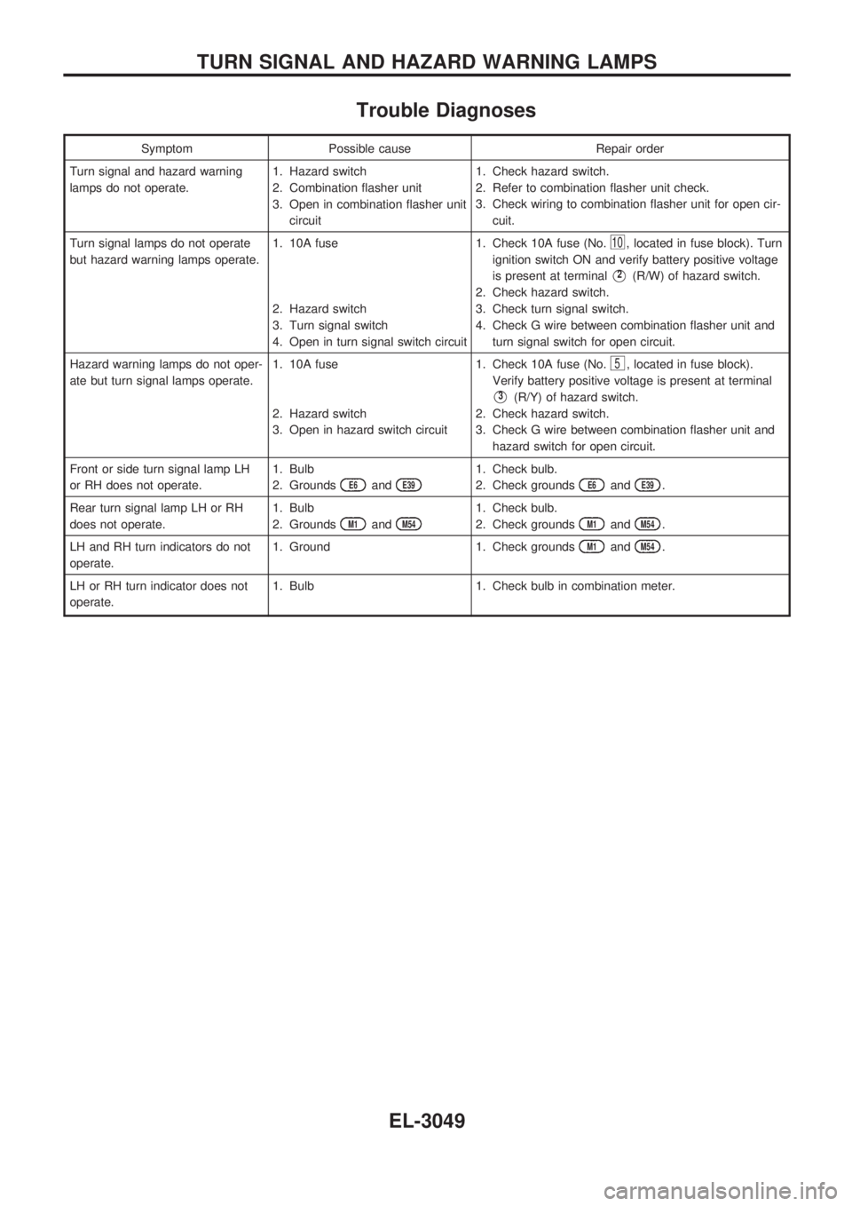
Trouble Diagnoses
Symptom Possible cause Repair order
Turn signal and hazard warning
lamps do not operate.1. Hazard switch
2. Combination flasher unit
3. Open in combination flasher unit
circuit1. Check hazard switch.
2. Refer to combination flasher unit check.
3. Check wiring to combination flasher unit for open cir-
cuit.
Turn signal lamps do not operate
but hazard warning lamps operate.1. 10A fuse
2. Hazard switch
3. Turn signal switch
4. Open in turn signal switch circuit1. Check 10A fuse (No.
10, located in fuse block). Turn
ignition switch ON and verify battery positive voltage
is present at terminal
V2(R/W) of hazard switch.
2. Check hazard switch.
3. Check turn signal switch.
4. Check G wire between combination flasher unit and
turn signal switch for open circuit.
Hazard warning lamps do not oper-
ate but turn signal lamps operate.1. 10A fuse
2. Hazard switch
3. Open in hazard switch circuit1. Check 10A fuse (No.
5, located in fuse block).
Verify battery positive voltage is present at terminal
V3(R/Y) of hazard switch.
2. Check hazard switch.
3. Check G wire between combination flasher unit and
hazard switch for open circuit.
Front or side turn signal lamp LH
or RH does not operate.1. Bulb
2. Grounds
E6andE39
1. Check bulb.
2. Check grounds
E6andE39.
Rear turn signal lamp LH or RH
does not operate.1. Bulb
2. Grounds
M1andM54
1. Check bulb.
2. Check grounds
M1andM54.
LH and RH turn indicators do not
operate.1. Ground 1. Check grounds
M1andM54.
LH or RH turn indicator does not
operate.1. Bulb 1. Check bulb in combination meter.
TURN SIGNAL AND HAZARD WARNING LAMPS
EL-3049
Page 748 of 1306

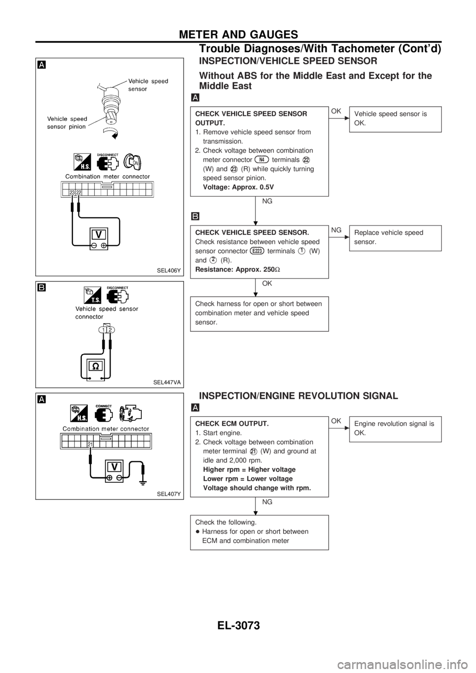
INSPECTION/VEHICLE SPEED SENSOR
Without ABS for the Middle East and Except for the
Middle East
CHECK VEHICLE SPEED SENSOR
OUTPUT.
1. Remove vehicle speed sensor from
transmission.
2. Check voltage between combination
meter connector
N4terminalsV22
(W) andV23(R) while quickly turning
speed sensor pinion.
Voltage: Approx. 0.5V
NG
cOK
Vehicle speed sensor is
OK.
CHECK VEHICLE SPEED SENSOR.
Check resistance between vehicle speed
sensor connector
E223terminalsV1(W)
and
V2(R).
Resistance: Approx. 250W
OK
cNG
Replace vehicle speed
sensor.
Check harness for open or short between
combination meter and vehicle speed
sensor.
INSPECTION/ENGINE REVOLUTION SIGNAL
CHECK ECM OUTPUT.
1. Start engine.
2. Check voltage between combination
meter terminal
V21(W) and ground at
idle and 2,000 rpm.
Higher rpm = Higher voltage
Lower rpm = Lower voltage
Voltage should change with rpm.
NG
cOK
Engine revolution signal is
OK.
Check the following.
+Harness for open or short between
ECM and combination meter
SEL406Y
SEL447VA
SEL407Y
.
.
.
METER AND GAUGES
Trouble Diagnoses/With Tachometer (Cont'd)
EL-3073