2001 NISSAN PICK-UP turn signal
[x] Cancel search: turn signalPage 482 of 1306
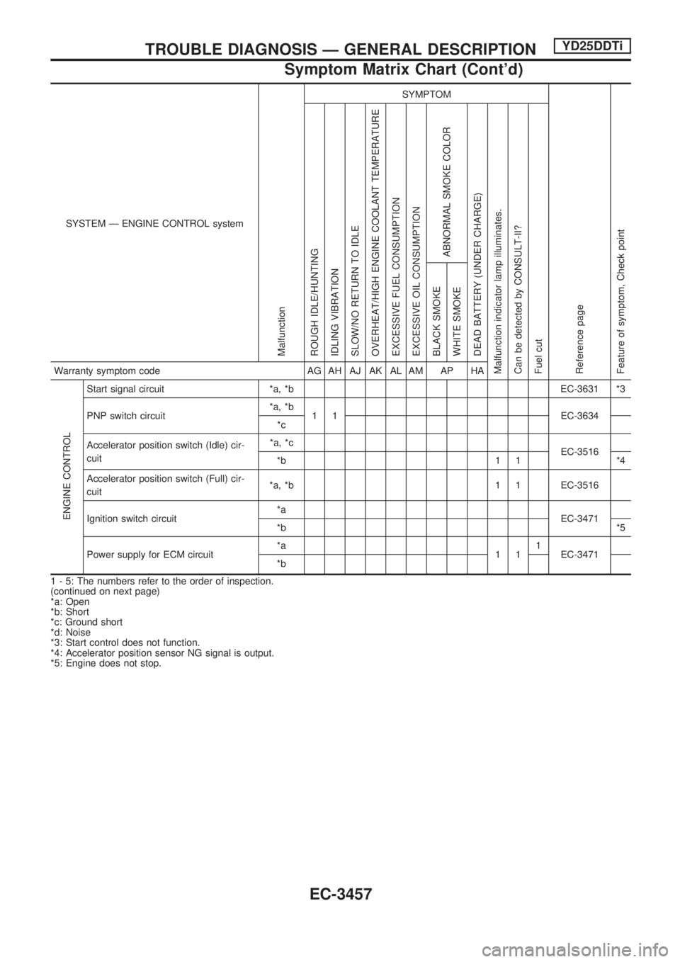
SYSTEM Ð ENGINE CONTROL system
Malfunction
SYMPTOM
Reference page
Feature of symptom, Check pointROUGH IDLE/HUNTING
IDLING VIBRATION
SLOW/NO RETURN TO IDLE
OVERHEAT/HIGH ENGINE COOLANT TEMPERATURE
EXCESSIVE FUEL CONSUMPTION
EXCESSIVE OIL CONSUMPTION
ABNORMAL SMOKE COLOR
DEAD BATTERY (UNDER CHARGE)
Malfunction indicator lamp illuminates.
Can be detected by CONSULT-II?
Fuel cutBLACK SMOKE
WHITE SMOKEWarranty symptom code AG AH AJ AK AL AM AP HA
ENGINE CONTROL
Start signal circuit *a, *b EC-3631 *3
PNP switch circuit*a, *b
1 1 EC-3634
*c
Accelerator position switch (Idle) cir-
cuit*a, *c
EC-3516
*b 1 1 *4
Accelerator position switch (Full) cir-
cuit*a, *b 1 1 EC-3516
Ignition switch circuit*a
EC-3471
*b*5
Power supply for ECM circuit*a
111
EC-3471
*b
1 - 5: The numbers refer to the order of inspection.
(continued on next page)
*a: Open
*b: Short
*c: Ground short
*d: Noise
*3: Start control does not function.
*4: Accelerator position sensor NG signal is output.
*5: Engine does not stop.
TROUBLE DIAGNOSIS Ð GENERAL DESCRIPTIONYD25DDTi
Symptom Matrix Chart (Cont'd)
EC-3457
Page 485 of 1306
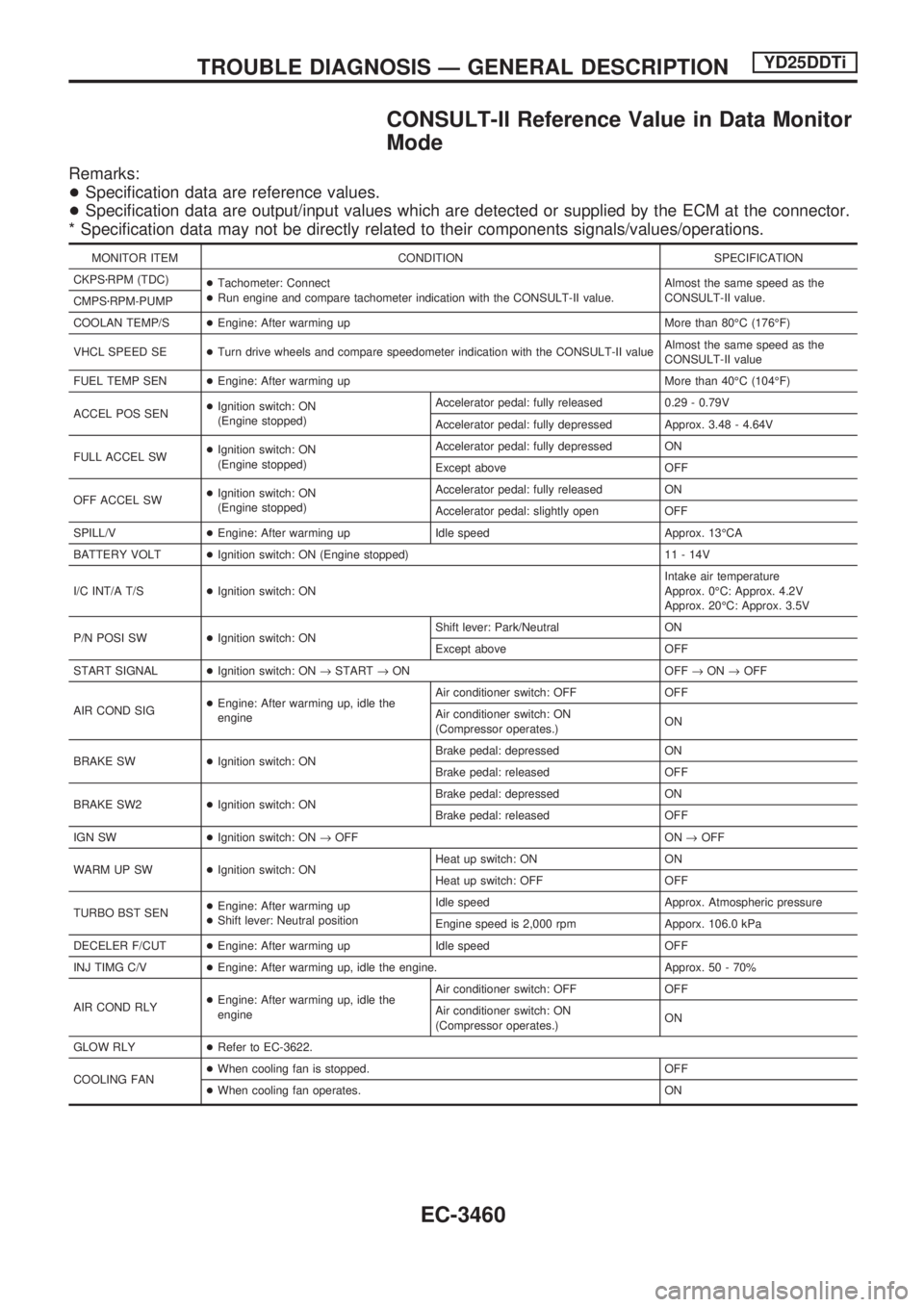
CONSULT-II Reference Value in Data Monitor
Mode
Remarks:
+Specification data are reference values.
+Specification data are output/input values which are detected or supplied by the ECM at the connector.
* Specification data may not be directly related to their components signals/values/operations.
MONITOR ITEM CONDITION SPECIFICATION
CKPSzRPM (TDC)
+Tachometer: Connect
+Run engine and compare tachometer indication with the CONSULT-II value.Almost the same speed as the
CONSULT-II value.
CMPSzRPM-PUMP
COOLAN TEMP/S+Engine: After warming up More than 80ÉC (176ÉF)
VHCL SPEED SE+Turn drive wheels and compare speedometer indication with the CONSULT-II valueAlmost the same speed as the
CONSULT-II value
FUEL TEMP SEN+Engine: After warming up More than 40ÉC (104ÉF)
ACCEL POS SEN+Ignition switch: ON
(Engine stopped)Accelerator pedal: fully released 0.29 - 0.79V
Accelerator pedal: fully depressed Approx. 3.48 - 4.64V
FULL ACCEL SW+Ignition switch: ON
(Engine stopped)Accelerator pedal: fully depressed ON
Except above OFF
OFF ACCEL SW+Ignition switch: ON
(Engine stopped)Accelerator pedal: fully released ON
Accelerator pedal: slightly open OFF
SPILL/V+Engine: After warming up Idle speed Approx. 13ÉCA
BATTERY VOLT+Ignition switch: ON (Engine stopped) 11 - 14V
I/C INT/A T/S+Ignition switch: ONIntake air temperature
Approx. 0ÉC: Approx. 4.2V
Approx. 20ÉC: Approx. 3.5V
P/N POSI SW+Ignition switch: ONShift lever: Park/Neutral ON
Except above OFF
START SIGNAL+Ignition switch: ON®START®ON OFF®ON®OFF
AIR COND SIG+Engine: After warming up, idle the
engineAir conditioner switch: OFF OFF
Air conditioner switch: ON
(Compressor operates.)ON
BRAKE SW+Ignition switch: ONBrake pedal: depressed ON
Brake pedal: released OFF
BRAKE SW2+Ignition switch: ONBrake pedal: depressed ON
Brake pedal: released OFF
IGN SW+Ignition switch: ON®OFF ON®OFF
WARM UP SW+Ignition switch: ONHeat up switch: ON ON
Heat up switch: OFF OFF
TURBO BST SEN+Engine: After warming up
+Shift lever: Neutral positionIdle speed Approx. Atmospheric pressure
Engine speed is 2,000 rpm Apporx. 106.0 kPa
DECELER F/CUT+Engine: After warming up Idle speed OFF
INJ TIMG C/V+Engine: After warming up, idle the engine. Approx. 50 - 70%
AIR COND RLY+Engine: After warming up, idle the
engineAir conditioner switch: OFF OFF
Air conditioner switch: ON
(Compressor operates.)ON
GLOW RLY+Refer to EC-3622.
COOLING FAN+When cooling fan is stopped. OFF
+When cooling fan operates. ON
TROUBLE DIAGNOSIS Ð GENERAL DESCRIPTIONYD25DDTi
EC-3460
Page 489 of 1306
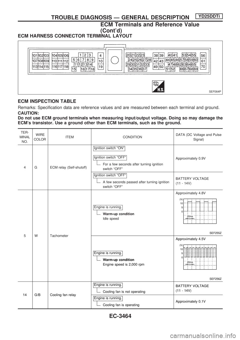
ECM HARNESS CONNECTOR TERMINAL LAYOUT
ECM INSPECTION TABLE
Remarks: Specification data are reference values and are measured between each terminal and ground.
CAUTION:
Do not use ECM ground terminals when measuring input/output voltage. Doing so may damage the
ECM's transistor. Use a ground other than ECM terminals, such as the ground.
TER-
MINAL
NO.WIRE
COLORITEM CONDITIONDATA (DC Voltage and Pulse
Signal)
4 G ECM relay (Self-shutoff)Ignition switch ªONº
Ignition switch ªOFFº
For a few seconds after turning ignition
switch ªOFFºApproximately 0.9V
Ignition switch ªOFFº
A few seconds passed after turning ignition
switch ªOFFºBATTERY VOLTAGE
(11 - 14V)
5 W TachometerEngine is running.
Warm-up condition
Idle speedApproximately 4.8V
SEF255Z
Engine is running.
Warm-up condition
Engine speed is 2,000 rpmApproximately 4.5V
SEF256Z
14 G/B Cooling fan relayEngine is running.Cooling fan is not operatingBATTERY VOLTAGE
(11 - 14V)
Engine is running.
Cooling fan is operatingApproximately 0.1V
SEF064P
TROUBLE DIAGNOSIS Ð GENERAL DESCRIPTIONYD25DDTi
ECM Terminals and Reference Value
(Cont'd)
EC-3464
Page 492 of 1306
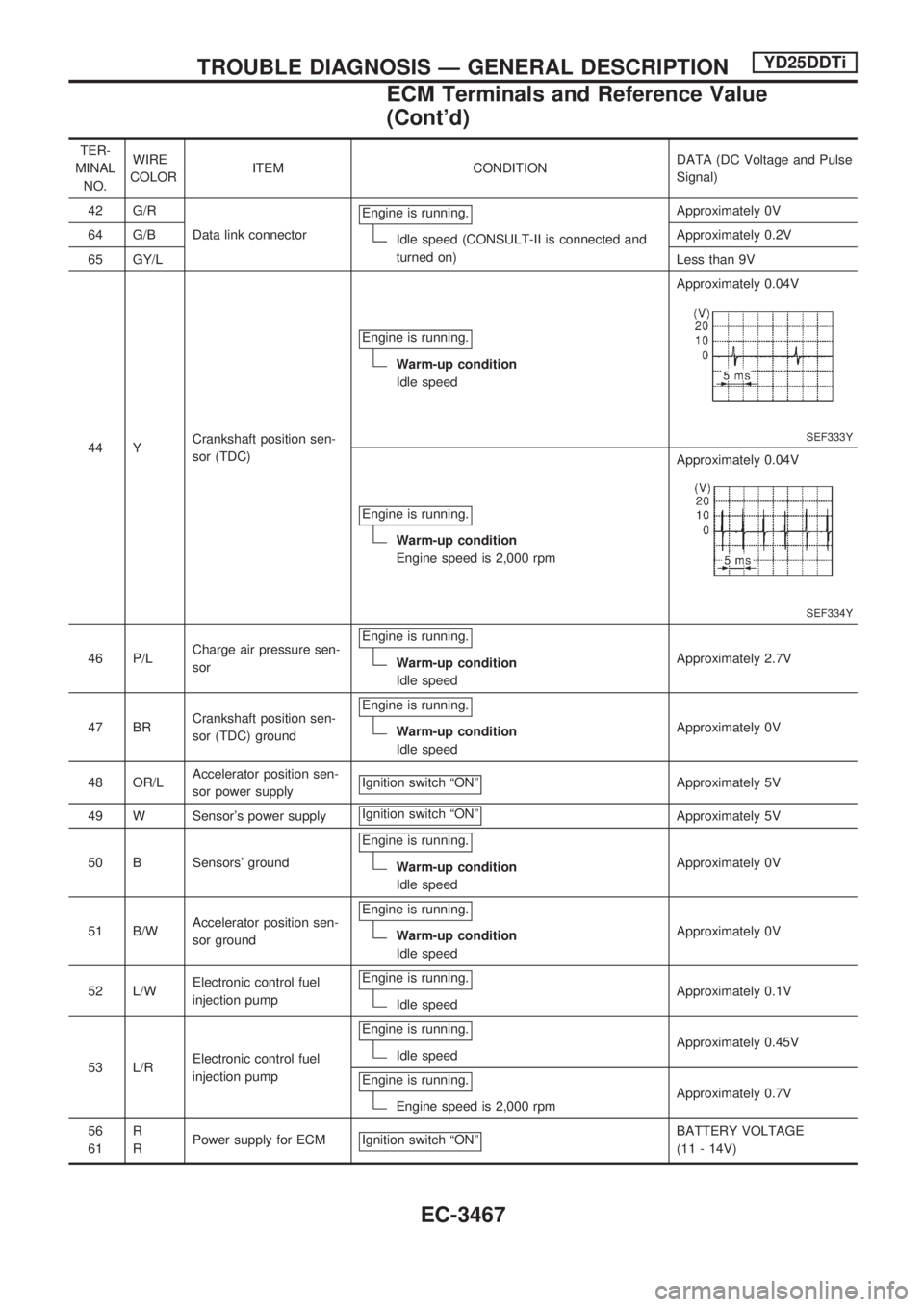
TER-
MINAL
NO.WIRE
COLORITEM CONDITIONDATA (DC Voltage and Pulse
Signal)
42 G/R
Data link connectorEngine is running.
Idle speed (CONSULT-II is connected and
turned on)Approximately 0V
64 G/BApproximately 0.2V
65 GY/LLess than 9V
44 YCrankshaft position sen-
sor (TDC)Engine is running.
Warm-up condition
Idle speedApproximately 0.04V
SEF333Y
Engine is running.
Warm-up condition
Engine speed is 2,000 rpmApproximately 0.04V
SEF334Y
46 P/LCharge air pressure sen-
sorEngine is running.Warm-up condition
Idle speedApproximately 2.7V
47 BRCrankshaft position sen-
sor (TDC) groundEngine is running.
Warm-up condition
Idle speedApproximately 0V
48 OR/LAccelerator position sen-
sor power supplyIgnition switch ªONº
Approximately 5V
49 W Sensor's power supplyIgnition switch ªONº
Approximately 5V
50 B Sensors' groundEngine is running.
Warm-up condition
Idle speedApproximately 0V
51 B/WAccelerator position sen-
sor groundEngine is running.
Warm-up condition
Idle speedApproximately 0V
52 L/WElectronic control fuel
injection pumpEngine is running.
Idle speedApproximately 0.1V
53 L/RElectronic control fuel
injection pumpEngine is running.
Idle speedApproximately 0.45V
Engine is running.
Engine speed is 2,000 rpmApproximately 0.7V
56
61R
RPower supply for ECM Ignition switch ªONº
BATTERY VOLTAGE
(11 - 14V)
TROUBLE DIAGNOSIS Ð GENERAL DESCRIPTIONYD25DDTi
ECM Terminals and Reference Value
(Cont'd)
EC-3467
Page 505 of 1306
Description
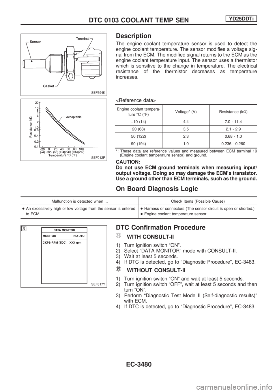
The engine coolant temperature sensor is used to detect the
engine coolant temperature. The sensor modifies a voltage sig-
nal from the ECM. The modified signal returns to the ECM as the
engine coolant temperature input. The sensor uses a thermistor
which is sensitive to the change in temperature. The electrical
resistance of the thermistor decreases as temperature
increases.
Engine coolant tempera-
ture ÉC (ÉF)Voltage* (V) Resistance (kW)
þ10 (14) 4.4 7.0 - 11.4
20 (68) 3.5 2.1 - 2.9
50 (122) 2.3 0.68 - 1.0
90 (194) 1.0 0.236 - 0.260
*: These data are reference values and measured between ECM terminal 19
(Engine coolant temperature sensor) and ground.
CAUTION:
Do not use ECM ground terminals when measuring input/
output voltage. Doing so may damage the ECM's transistor.
Use a ground other than ECM terminals, such as the ground.
On Board Diagnosis Logic
Malfunction is detected when ... Check Items (Possible Cause)
+An excessively high or low voltage from the sensor is entered
to ECM.+Harness or connectors (The sensor circuit is open or shorted.)
+Engine coolant temperature sensor
DTC Confirmation Procedure
WITH CONSULT-II
1) Turn ignition switch ªONº.
2) Select ªDATA MONITORº mode with CONSULT-II.
3) Wait at least 5 seconds.
4) If DTC is detected, go to ªDiagnostic Procedureº, EC-3483.
WITHOUT CONSULT-II
1) Turn ignition switch ªONº and wait at least 5 seconds.
2) Turn ignition switch ªOFFº, wait at least 5 seconds and then
turn ªONº.
3) Perform ªDiagnostic Test Mode II (Self-diagnostic results)º
with ECM.
4) If DTC is detected, go to ªDiagnostic Procedureº, EC-3483.
SEF594K
SEF012P
SEF817Y
DTC 0103 COOLANT TEMP SENYD25DDTi
EC-3480
Page 513 of 1306
Diagnostic Procedure
1 CHECK VEHICLE SPEED SENSOR INPUT SIGNAL CIRCUIT FOR OPEN AND SHORT
1. Turn ignition switch ªOFFº.
2. Disconnect ECM harness connector and combination meter harness connector.
3. Check harness continuity between ECM terminal 26 and combination meter terminal 57 (models with tachometer) or 28 (models
without tachometer). Refer to Wiring Diagram.
Continuity should exist.
4. Also check harness for short to ground and short to power.
OK or NG
OKcGO TO 3.
NGcGO TO 2.
2 DETECT MALFUNCTIONING PART
Check the following.
+Harness connectors N2, M7
+Harness connectors M48, F54 (RHD models)
+Harness for open or short between ECM and combination meter
cRepair open circuit or short to ground or short to power in harness or connectors.
3 CHECK SPEEDOMETER FUNCTION
Make sure that speedometer functions properly.
OK or NG
OKcGO TO 5.
NGcGO TO 4.
4 CHECK SPEEDOMETER CIRCUIT FOR OPEN AND SHORT
Check the following.
+Harness connectors N2, M7
+Harness connectors M5, E101
+Harness connectors E33, E205
+Harness for open or short between combination meter and vehicle speed sensor
OK or NG
OKcCheck vehicle speed sensor and combination meter. Refer to EL section.
NGcRepair open circuit or short to ground or short to power in harness or connectors.
5 CHECK INTERMITTENT INCIDENT
Refer to ªTROUBLE DIAGNOSIS FOR INTERMITTENT INCIDENTº, EC-3469.
cINSPECTION END
DTC 0104 VEHICLE SPEED SENYD25DDTi
EC-3488
Page 521 of 1306

6 CHECK COOLING FAN GROUND CIRCUIT FOR OPEN AND SHORT
1. Turn ignition switch ªOFFº.
2. Disconnect cooling fan motor harness connector.
SEC232D
3. Check harness continuity between cooling fan relay terminal 3 and cooling fan motor terminals 1, cooling fan motor terminals 2
and body ground. Refer to Wiring Diagram.
Continuity should exist.
4. Also check harness for short to ground and short to power.
OK or NG
OKcGO TO 7.
NGcRepair open circuit or short to ground or short to power in harness or connectors.
7 CHECK COOLING FAN OUTPUT SIGNAL CIRCUIT FOR OPEN AND SHORT
1. Disconnect ECM harness connector.
2. Disconnect triple-pressure switch harness connector.
3. Check harness continuity between ECM terminal 14 and cooling fan relay terminal 1, cooling fan relay terminal 1 and triple-pres-
sure switch terminal 2, triple-pressure switch terminal 3 and ground. Refer to Wiring Diagram.
Continuity should exist.
4. Also check harness for short to ground and short to power.
OK or NG
OKcGO TO 9.
NGcGO TO 8.
8 DETECT MALFUNCTIONING PART
Check the following.
+Harness connectors M5, E101
+Harness connectors M47, F55 (RHD models)
+Harness for open or short between cooling fan relay and ECM
+Harness for open or short between cooling fan relay and triple-pressure switch
+Harness for open or short between triple-pressure switch and ground
cRepair open circuit or short to ground or short to power in harness or connectors.
DTC 0208 OVER HEATYD25DDTi
Diagnostic Procedure (Cont'd)
EC-3496
Page 526 of 1306
Description
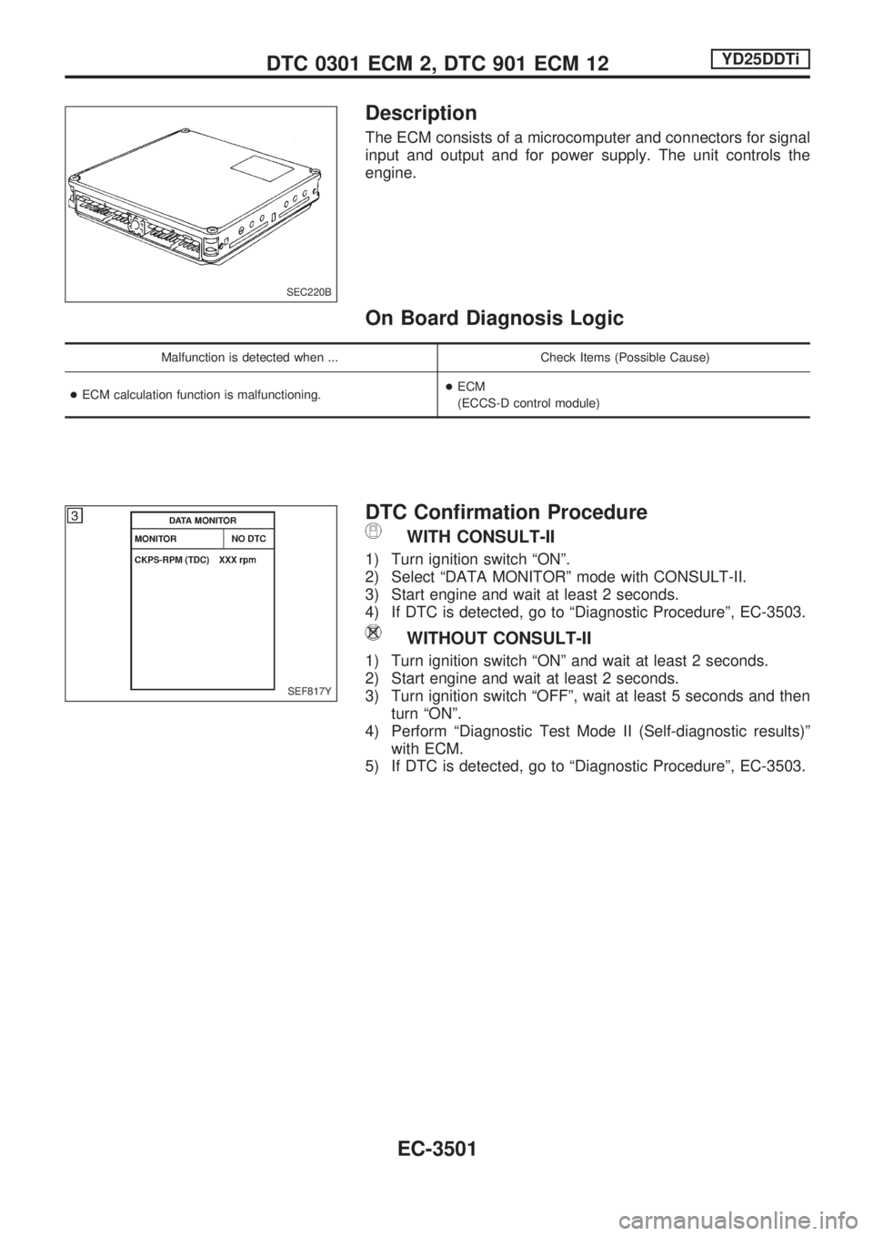
The ECM consists of a microcomputer and connectors for signal
input and output and for power supply. The unit controls the
engine.
On Board Diagnosis Logic
Malfunction is detected when ... Check Items (Possible Cause)
+ECM calculation function is malfunctioning.+ECM
(ECCS-D control module)
DTC Confirmation Procedure
WITH CONSULT-II
1) Turn ignition switch ªONº.
2) Select ªDATA MONITORº mode with CONSULT-II.
3) Start engine and wait at least 2 seconds.
4) If DTC is detected, go to ªDiagnostic Procedureº, EC-3503.
WITHOUT CONSULT-II
1) Turn ignition switch ªONº and wait at least 2 seconds.
2) Start engine and wait at least 2 seconds.
3) Turn ignition switch ªOFFº, wait at least 5 seconds and then
turn ªONº.
4) Perform ªDiagnostic Test Mode II (Self-diagnostic results)º
with ECM.
5) If DTC is detected, go to ªDiagnostic Procedureº, EC-3503.
SEC220B
SEF817Y
DTC 0301 ECM 2, DTC 901 ECM 12YD25DDTi
EC-3501