Page 309 of 1306

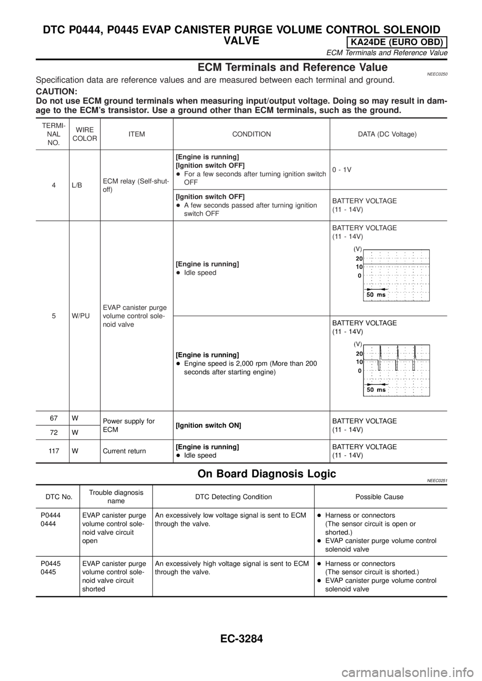
ECM Terminals and Reference ValueNEEC0250Specification data are reference values and are measured between each terminal and ground.
CAUTION:
Do not use ECM ground terminals when measuring input/output voltage. Doing so may result in dam-
age to the ECM's transistor. Use a ground other than ECM terminals, such as the ground.
TERMI-
NAL
NO.WIRE
COLORITEM CONDITION DATA (DC Voltage)
4 L/BECM relay (Self-shut-
off)[Engine is running]
[Ignition switch OFF]
+For a few seconds after turning ignition switch
OFF0-1V
[Ignition switch OFF]
+A few seconds passed after turning ignition
switch OFFBATTERY VOLTAGE
(11 - 14V)
5 W/PUEVAP canister purge
volume control sole-
noid valve[Engine is running]
+Idle speedBATTERY VOLTAGE
(11 - 14V)
[Engine is running]
+Engine speed is 2,000 rpm (More than 200
seconds after starting engine)BATTERY VOLTAGE
(11 - 14V)
67 W
Power supply for
ECM[Ignition switch ON]BATTERY VOLTAGE
(11 - 14V)
72 W
117 W Current return[Engine is running]
+Idle speedBATTERY VOLTAGE
(11 - 14V)
On Board Diagnosis LogicNEEC0251
DTC No.Trouble diagnosis
nameDTC Detecting Condition Possible Cause
P0444
0444EVAP canister purge
volume control sole-
noid valve circuit
openAn excessively low voltage signal is sent to ECM
through the valve.+Harness or connectors
(The sensor circuit is open or
shorted.)
+EVAP canister purge volume control
solenoid valve
P0445
0445EVAP canister purge
volume control sole-
noid valve circuit
shortedAn excessively high voltage signal is sent to ECM
through the valve.+Harness or connectors
(The sensor circuit is shorted.)
+EVAP canister purge volume control
solenoid valve
DTC P0444, P0445 EVAP CANISTER PURGE VOLUME CONTROL SOLENOID
VALVE
KA24DE (EURO OBD)
ECM Terminals and Reference Value
EC-3284
Page 312 of 1306

Diagnostic ProcedureNEEC0254
1 CHECK POWER SUPPLY
1. Turn ignition switch OFF.
2. Disconnect EVAP canister purge volume control solenoid valve harness connector.
SEC307D
3. Turn ignition switch ON.
4. Check voltage between terminal 1 and ground with CONSULT-II or tester.
SEC275D
Voltage: Battery voltage
OK or NG
OK©GO TO 3.
NG©GO TO 2.
2 DETECT MALFUNCTIONING PART
Check the following.
+Harness connectors E101, M5
+Harness for open or short between EVAP canister purge volume control solenoid valve and ECM relay
+Harness for open or short between EVAP canister purge volume control solenoid valve and ECM
©Repair harness or connectors.
3 CHECK OUTPUT SIGNAL CIRCUIT
1. Turn ignition switch OFF.
2. Disconnect ECM harness connector.
3. Check harness continuity between ECM terminal 5 and terminal 2. Refer to wiring diagram.
Continuity should exist.
4. Also, check harness for short to ground and short to power.
OK or NG
OK (With CONSULT-II)©GO TO 5.
OK (Without CONSULT-
II)©GO TO 6.
NG©GO TO 4.
DTC P0444, P0445 EVAP CANISTER PURGE VOLUME CONTROL SOLENOID
VALVE
KA24DE (EURO OBD)
Diagnostic Procedure
EC-3287
Page 315 of 1306

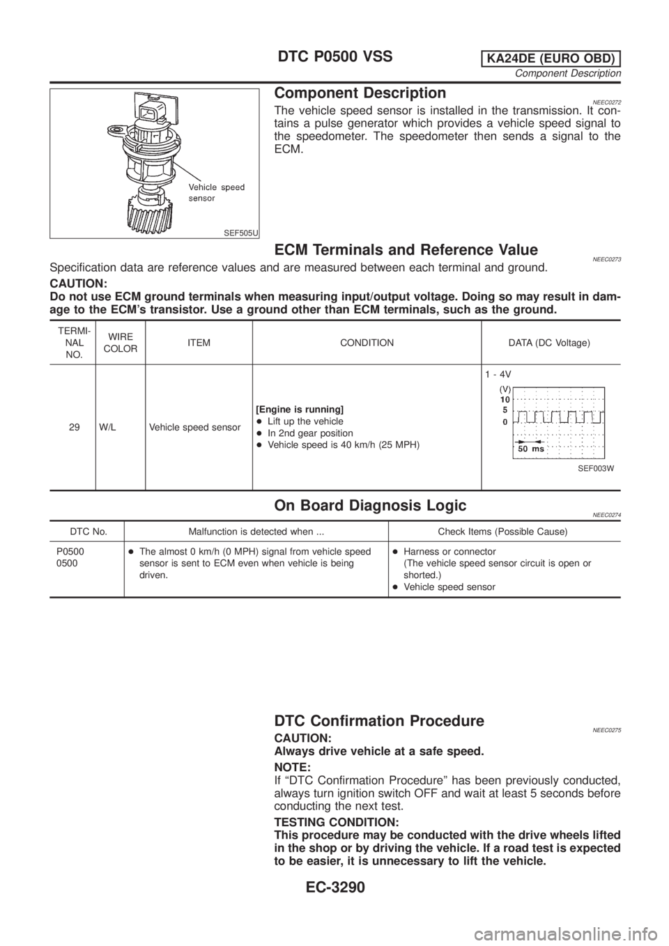
SEF505U
Component DescriptionNEEC0272The vehicle speed sensor is installed in the transmission. It con-
tains a pulse generator which provides a vehicle speed signal to
the speedometer. The speedometer then sends a signal to the
ECM.
ECM Terminals and Reference ValueNEEC0273Specification data are reference values and are measured between each terminal and ground.
CAUTION:
Do not use ECM ground terminals when measuring input/output voltage. Doing so may result in dam-
age to the ECM's transistor. Use a ground other than ECM terminals, such as the ground.
TERMI-
NAL
NO.WIRE
COLORITEM CONDITION DATA (DC Voltage)
29 W/L Vehicle speed sensor[Engine is running]
+Lift up the vehicle
+In 2nd gear position
+Vehicle speed is 40 km/h (25 MPH)1-4V
SEF003W
On Board Diagnosis LogicNEEC0274
DTC No. Malfunction is detected when ... Check Items (Possible Cause)
P0500
0500+The almost 0 km/h (0 MPH) signal from vehicle speed
sensor is sent to ECM even when vehicle is being
driven.+Harness or connector
(The vehicle speed sensor circuit is open or
shorted.)
+Vehicle speed sensor
DTC Confirmation ProcedureNEEC0275CAUTION:
Always drive vehicle at a safe speed.
NOTE:
If ªDTC Confirmation Procedureº has been previously conducted,
always turn ignition switch OFF and wait at least 5 seconds before
conducting the next test.
TESTING CONDITION:
This procedure may be conducted with the drive wheels lifted
in the shop or by driving the vehicle. If a road test is expected
to be easier, it is unnecessary to lift the vehicle.
DTC P0500 VSSKA24DE (EURO OBD)
Component Description
EC-3290
Page 319 of 1306

Diagnostic ProcedureNEEC1054WITH TACHOMETERNEEC1054S01
1 CHECK INPUT SIGNAL CIRCUIT
1. Turn ignition switch OFF.
2. Disconnect ECM harness connector and combination meter harness connector.
MTBL1308
3. Check harness continuity between ECM terminal 29 and meter terminal 57 (With tachometer), 28 (Without tachometer).
Refer to Wiring Diagram.
Continuity should exist.
4. Also check harness for short to ground and short to power.
OK or NG
OK©GO TO 3.
NG©GO TO 2.
2 DETECT MALFUNCTIONING PART
Check the following.
+Harness connectors N2, M7
+Harness for open or short between ECM and combination meter
©Repair open circuit or short to ground or short to power in harness or connectors.
3 CHECK SPEEDOMETER FUNCTION
Make sure that speedometer functions properly.
OK or NG
OK©GO TO 5.
NG©GO TO 4.
4 DETECT MALFUNCTIONING PART
Check the following.
+Harness connectors N2, M7
+Harness connectors M5, E101
+Harness connectors E30, E203
+Harness for open or short between combination meter and vehicle speed sensor
©Repair harness or connectors. Check vehicle speed sensor and its circuit. Refer to EL
section.
5 CHECK INTERMITTENT INCIDENT
Perform ªTROUBLE DIAGNOSIS FOR INTERMITTENT INCIDENTº, EC-3123.
©INSPECTION END
DTC P0500 VSSKA24DE (EURO OBD)
Diagnostic Procedure
EC-3294
Page 324 of 1306
Diagnostic ProcedureNEEC1600
1 CHECK POWER SUPPLY
1. Stop engine.
2. Disconnect IACV-AAC valve harness connector.
SEF342V
3. Turn ignition switch ON.
4. Check voltage between terminal 2 and ground with CONSULT-II or tester.
SEC271D
Voltage: Battery voltage
OK or NG
OK©GO TO 3.
NG©GO TO 2.
2 DETECT MALFUNCTIONING PART
Check the following.
+10A fuse
+Harness for open or short between IACV-AAC valve and 10A fuse
©Repair harness or connectors.
3 CHECK OUTPUT SIGNAL CIRCUIT
1. Turn ignition switch OFF.
2. Disconnect ECM harness connector.
3. Check harness continuity between ECM terminal 101 and terminal 1. Refer to wiring diagram.
Continuity should exist.
4. Also check harness for short to ground and short to power.
OK or NG
OK©GO TO 4.
NG©Repair open circuit or short to ground or short to power in harness or connectors.
DTC P0505 ISC SYSTEMKA24DE (EURO OBD)
Diagnostic Procedure
EC-3299
Page 327 of 1306

SEF197Y
SEF198Y
DTC Confirmation Procedure=NEEC0290CAUTION:
Always drive vehicle at a safe speed.
NOTE:
If ªDTC Confirmation Procedureº has been previously conducted,
always turn ignition switch OFF and wait at least 5 seconds before
conducting the next test.
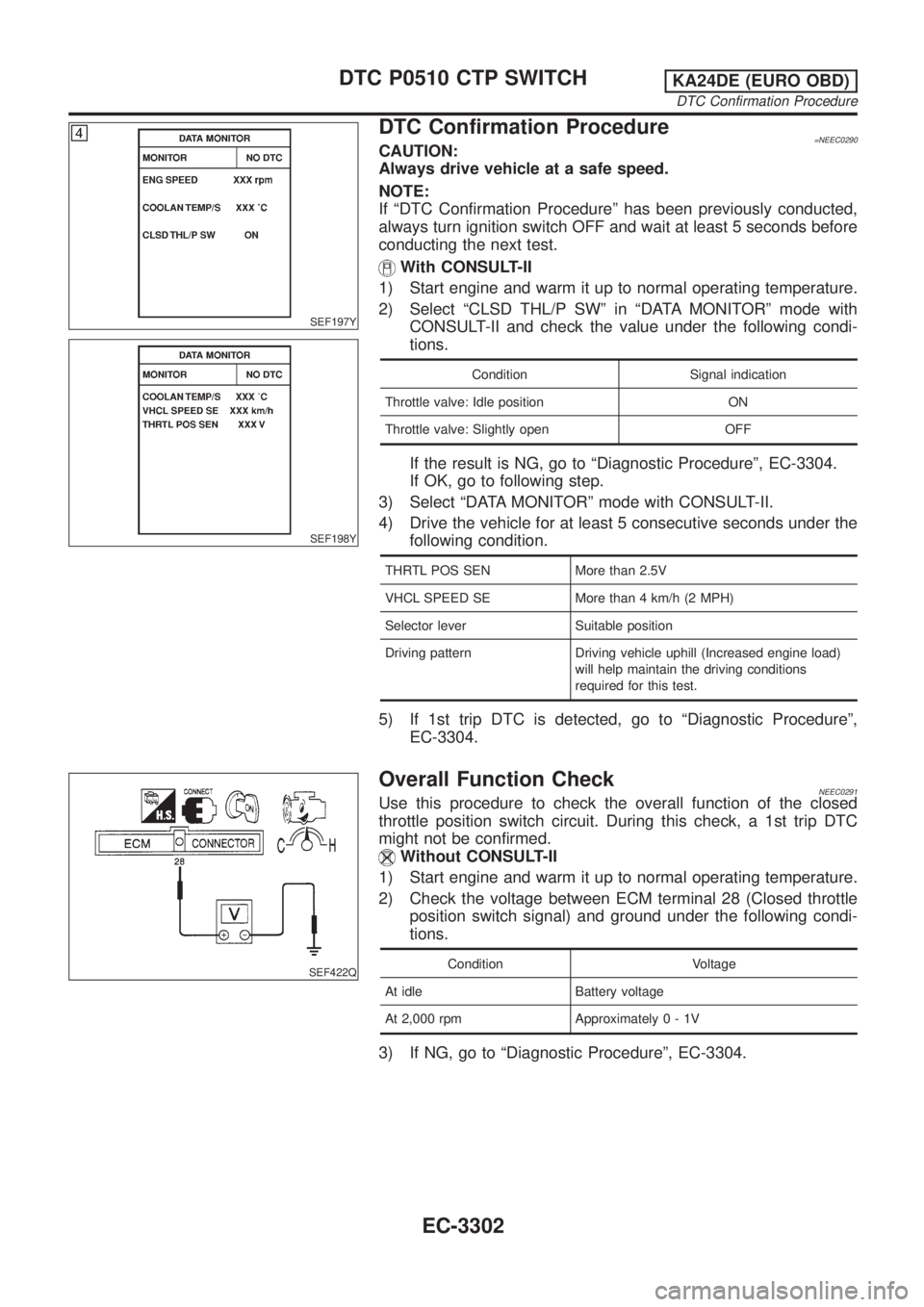
With CONSULT-II
1) Start engine and warm it up to normal operating temperature.
2) Select ªCLSD THL/P SWº in ªDATA MONITORº mode with
CONSULT-II and check the value under the following condi-
tions.
Condition Signal indication
Throttle valve: Idle position ON
Throttle valve: Slightly open OFF
If the result is NG, go to ªDiagnostic Procedureº, EC-3304.
If OK, go to following step.
3) Select ªDATA MONITORº mode with CONSULT-II.
4) Drive the vehicle for at least 5 consecutive seconds under the
following condition.
THRTL POS SEN More than 2.5V
VHCL SPEED SE More than 4 km/h (2 MPH)
Selector lever Suitable position
Driving pattern Driving vehicle uphill (Increased engine load)
will help maintain the driving conditions
required for this test.
5) If 1st trip DTC is detected, go to ªDiagnostic Procedureº,
EC-3304.
SEF422Q
Overall Function CheckNEEC0291Use this procedure to check the overall function of the closed
throttle position switch circuit. During this check, a 1st trip DTC
might not be confirmed.
Without CONSULT-II
1) Start engine and warm it up to normal operating temperature.
2) Check the voltage between ECM terminal 28 (Closed throttle
position switch signal) and ground under the following condi-
tions.
Condition Voltage
At idle Battery voltage
At 2,000 rpm Approximately0-1V
3) If NG, go to ªDiagnostic Procedureº, EC-3304.
DTC P0510 CTP SWITCHKA24DE (EURO OBD)
DTC Confirmation Procedure
EC-3302
Page 330 of 1306
3 CHECK INPUT SIGNAL CIRCUIT
1. Turn ignition switch OFF.
2. Disconnect ECM harness connector.
3. Check harness continuity between ECM terminal 28 and terminal 6.
AEC571A
Continuity should exist.
4. Also check harness for short to ground and short to power.
OK or NG
OK©GO TO 5.
NG©GO TO 4.
4 DETECT MALFUNCTIONING PART
Check the harness for open or short between throttle position switch and ECM.
©Repair open circuit or short to ground or short to power in harness or connectors.
5 ADJUST THROTTLE POSITION SWITCH IDLE POSITION
1. Check the following items. Refer to ªBasic Inspectionº, EC-3086.
MTBL1315
©GO TO 6.
DTC P0510 CTP SWITCHKA24DE (EURO OBD)
Diagnostic Procedure
EC-3305
Page 332 of 1306

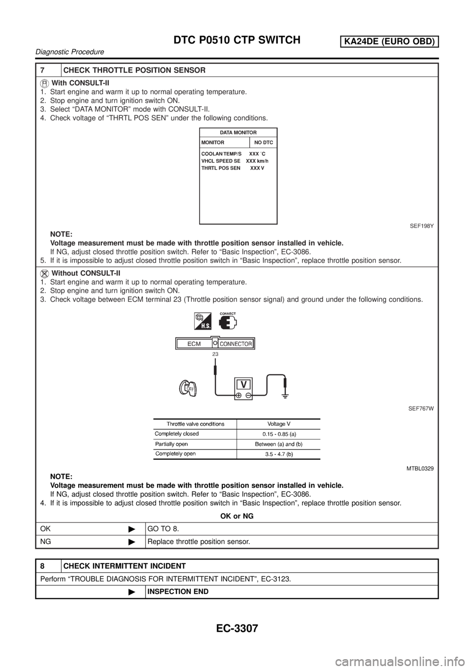
7 CHECK THROTTLE POSITION SENSOR
With CONSULT-II
1. Start engine and warm it up to normal operating temperature.
2. Stop engine and turn ignition switch ON.
3. Select ªDATA MONITORº mode with CONSULT-II.
4. Check voltage of ªTHRTL POS SENº under the following conditions.
SEF198Y
NOTE:
Voltage measurement must be made with throttle position sensor installed in vehicle.
If NG, adjust closed throttle position switch. Refer to ªBasic Inspectionº, EC-3086.
5. If it is impossible to adjust closed throttle position switch in ªBasic Inspectionº, replace throttle position sensor.
Without CONSULT-II
1. Start engine and warm it up to normal operating temperature.
2. Stop engine and turn ignition switch ON.
3. Check voltage between ECM terminal 23 (Throttle position sensor signal) and ground under the following conditions.
SEF767W
MTBL0329
NOTE:
Voltage measurement must be made with throttle position sensor installed in vehicle.
If NG, adjust closed throttle position switch. Refer to ªBasic Inspectionº, EC-3086.
4. If it is impossible to adjust closed throttle position switch in ªBasic Inspectionº, replace throttle position sensor.
OK or NG
OK©GO TO 8.
NG©Replace throttle position sensor.
8 CHECK INTERMITTENT INCIDENT
Perform ªTROUBLE DIAGNOSIS FOR INTERMITTENT INCIDENTº, EC-3123.
©INSPECTION END
DTC P0510 CTP SWITCHKA24DE (EURO OBD)
Diagnostic Procedure
EC-3307