Page 182 of 1306
6 CHECK GROUND CIRCUIT
1. Turn ignition switch OFF.
2. Disconnect ECM harness connector.
3. Check harness continuity between mass air flow sensor terminal 2 and ECM terminal 55. Refer to EC-3154.
SEF124V
Continuity should exist.
4. Also check harness for short to ground or short to power.
OK or NG
OK©GO TO 7.
NG©Repair open circuit or short to ground or short to power in harness or connectors.
7 CHECK INPUT SIGNAL CIRCUIT
1. Check harness continuity between terminal 1 and ECM terminal 54. Refer to wiring diagram.
Continuity should exist.
2. Also check harness for short to ground and short to power.
OK or NG
OK©GO TO 8.
NG©Repair open circuit or short to ground or short to power in harness or connectors.
DTC P0102, P0103 MAF SENSORKA24DE (EURO OBD)
Diagnostic Procedure
EC-3157
Page 183 of 1306
8 CHECK MASS AIR FLOW SENSOR
1. Reconnect all harness connectors disconnected.
2. Turn ignition switch ON.
3. Start engine and warm it up to normal operating temperature.
4. Check voltage between ECM terminal 54 (mass air flow sensor signal) and ground.
SEF326V
MTBL0326
5. If the voltage is out of specification, disconnect mass air flow sensor harness connector and connect it again. Repeat
above check.
6. If NG, remove mass air flow sensor from air duct. Check hot wire for damage or dust.
SEF893J
OK or NG
OK©GO TO 9.
NG©Replace mass air flow sensor.
DTC P0102, P0103 MAF SENSORKA24DE (EURO OBD)
Diagnostic Procedure
EC-3158
Page 190 of 1306

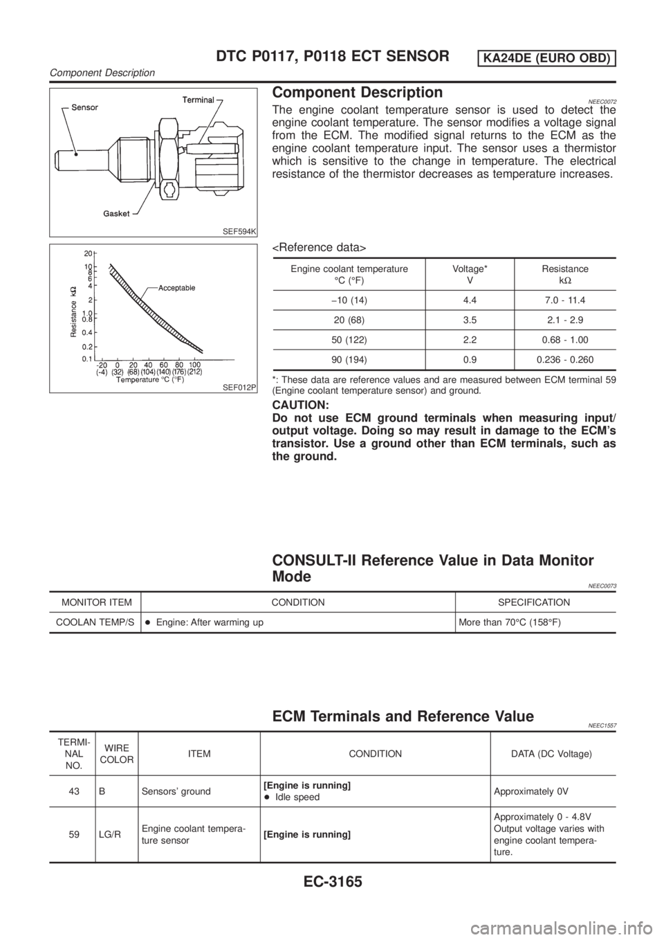
SEF594K
Component DescriptionNEEC0072The engine coolant temperature sensor is used to detect the
engine coolant temperature. The sensor modifies a voltage signal
from the ECM. The modified signal returns to the ECM as the
engine coolant temperature input. The sensor uses a thermistor
which is sensitive to the change in temperature. The electrical
resistance of the thermistor decreases as temperature increases.
SEF012P
Engine coolant temperature
ÉC (ÉF)Voltage*
VResistance
kW
þ10 (14) 4.4 7.0 - 11.4
20 (68) 3.5 2.1 - 2.9
50 (122) 2.2 0.68 - 1.00
90 (194) 0.9 0.236 - 0.260
*: These data are reference values and are measured between ECM terminal 59
(Engine coolant temperature sensor) and ground.
CAUTION:
Do not use ECM ground terminals when measuring input/
output voltage. Doing so may result in damage to the ECM's
transistor. Use a ground other than ECM terminals, such as
the ground.
CONSULT-II Reference Value in Data Monitor
Mode
NEEC0073
MONITOR ITEM CONDITION SPECIFICATION
COOLAN TEMP/S+Engine: After warming up More than 70ÉC (158ÉF)
ECM Terminals and Reference ValueNEEC1557
TERMI-
NAL
NO.WIRE
COLORITEM CONDITION DATA (DC Voltage)
43 B Sensors' ground[Engine is running]
+Idle speedApproximately 0V
59 LG/REngine coolant tempera-
ture sensor[Engine is running]Approximately 0 - 4.8V
Output voltage varies with
engine coolant tempera-
ture.
DTC P0117, P0118 ECT SENSORKA24DE (EURO OBD)
Component Description
EC-3165
Page 202 of 1306

7 DETECT MALFUNCTIONING PART
Check harness for open or short between ECM and throttle position sensor.
©Repair open circuit or short to power in harness or connectors.
8 CHECK INPUT SIGNAL CIRCUIT
1. Disconnect ECM harness connector.
2. Check harness continuity between ECM terminal 23 and terminal 2.
Refer to the Wiring Diagram.
Continuity should exist.
3. Also check harness for short to ground and short to power.
OK or NG
OK (With CONSULT-II)©GO TO 9.
OK (Without CONSULT-
II)©GO TO 10.
NG©Repair open circuit or short to ground or short to power in harness or connectors.
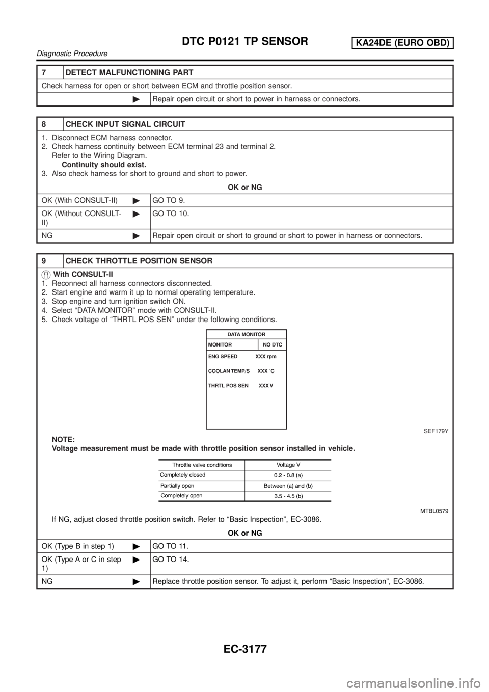
9 CHECK THROTTLE POSITION SENSOR
With CONSULT-II
1. Reconnect all harness connectors disconnected.
2. Start engine and warm it up to normal operating temperature.
3. Stop engine and turn ignition switch ON.
4. Select ªDATA MONITORº mode with CONSULT-II.
5. Check voltage of ªTHRTL POS SENº under the following conditions.
SEF179Y
NOTE:
Voltage measurement must be made with throttle position sensor installed in vehicle.
MTBL0579
If NG, adjust closed throttle position switch. Refer to ªBasic Inspectionº, EC-3086.
OK or NG
OK (Type B in step 1)©GO TO 11.
OK (Type A or C in step
1)©GO TO 14.
NG©Replace throttle position sensor. To adjust it, perform ªBasic Inspectionº, EC-3086.
DTC P0121 TP SENSORKA24DE (EURO OBD)
Diagnostic Procedure
EC-3177
Page 203 of 1306
10 CHECK THROTTLE POSITION SENSOR
Without CONSULT-II
1. Reconnect all harness connectors disconnected.
2. Start engine and warm it up to normal operating temperature.
3. Stop engine and turn ignition switch ON.
4. Check voltage between ECM terminal 23 (Throttle position sensor signal) and ground under the following conditions.
SEF767W
NOTE:
Voltage measurement must be made with throttle position sensor installed in vehicle.
MTBL0579
If NG, adjust closed throttle position switch. Refer to ªBasic Inspectionº, EC-3086.
OK or NG
OK (Type B in step 1)©GO TO 11.
OK (Type A or C in step
1)©GO TO 14.
NG©Replace throttle position sensor. To adjust it, perform ªBasic Inspectionº, EC-3086.
DTC P0121 TP SENSORKA24DE (EURO OBD)
Diagnostic Procedure
EC-3178
Page 204 of 1306
11 CHECK MASS AIR FLOW SENSOR
1. Turn ignition switch ON.
2. Start engine and warm it up to normal operating temperature.
3. Check voltage between ECM terminal 54 (mass air flow sensor signal) and ground.
SEF326V
MTBL0326
4. If the voltage is out of specification, disconnect mass air flow sensor harness connector and connect it again. Repeat
above check.
5. If NG, remove mass air flow sensor from air duct. Check hot wire for damage or dust.
SEF893J
OK or NG
OK©GO TO 12.
NG©Replace mass air flow sensor.
DTC P0121 TP SENSORKA24DE (EURO OBD)
Diagnostic Procedure
EC-3179
Page 212 of 1306
3 CHECK GROUND CIRCUIT
1. Turn ignition switch OFF.
2. Check harness continuity between throttle position sensor terminal 3 and engine ground. Refer to the Wiring Diagram.
SEF565P
Continuity should exist.
3. Also check harness for short to power.
OK or NG
OK©GO TO 5.
NG©GO TO 4.
4 DETECT MALFUNCTIONING PART
Check harness for open or short between ECM and throttle position sensor.
©Repair open circuit or short to power in harness or connectors.
5 CHECK INPUT SIGNAL CIRCUIT
1. Disconnect ECM harness connector.
2. Check harness continuity between ECM terminal 23 and terminal 2.
Refer to the Wiring Diagram.
Continuity should exist.
3. Also check harness for short to ground and short to power.
OK or NG
OK (With CONSULT-II)©GO TO 6.
OK (Without CONSULT-
II)©GO TO 7.
NG©Repair open circuit or short to ground or short to power in harness or connectors.
DTC P0122, P0123 TP SENSORKA24DE (EURO OBD)
Diagnostic Procedure
EC-3187
Page 214 of 1306
7 CHECK THROTTLE POSITION SENSOR
Without CONSULT-II
1. Reconnect all harness connectors disconnected.
2. Start engine and warm it up to normal operating temperature.
3. Stop engine and turn ignition switch ON.
4. Check voltage between ECM terminal 23 (Throttle position sensor signal) and ground under the following conditions.
SEF767W
NOTE:
Voltage measurement must be made with throttle position sensor installed in vehicle.
MTBL0579
If NG, adjust closed throttle position switch. Refer to ªBasic Inspectionº, EC-3086.
OK or NG
OK (Type B in step 1)©GO TO 8.
OK (Type A or C in step
1)©GO TO 11.
NG©Replace throttle position sensor. To adjust it, perform ªBasic Inspectionº, EC-3086.
DTC P0122, P0123 TP SENSORKA24DE (EURO OBD)
Diagnostic Procedure
EC-3189