2001 NISSAN PICK-UP turn signal
[x] Cancel search: turn signalPage 53 of 1306

Air Conditioning Cut Control
DESCRIPTION=NEEC0016Input/Output Signal ChartNEEC0016S01
Sensor Input Signal to ECMECM func-
tionActuator
Air conditioner switch Air conditioner ªONº signal
Air condi-
tioner cut
controlAir conditioner relay Throttle position sensor Throttle valve opening angle
Camshaft position sensor Engine speed
Engine coolant temperature sensor Engine coolant temperature
Ignition switch Start signal
Vehicle speed sensor Vehicle speed
Power steering oil pressure switch Power steering operation
System DescriptionNEEC0016S02This system improves engine operation when the air conditioner is used.
Under the following conditions, the air conditioner is turned off.
+When the accelerator pedal is fully depressed.
+When cranking the engine.
+When the engine coolant temperature becomes excessively high.
+When operating power steering and air conditioner during low engine speed or when fully releasing accel-
erator pedal.
+When engine speed is excessively low.
Fuel Cut Control (at no load & high engine
speed)
DESCRIPTIONNEEC0017Input/Output Signal ChartNEEC0017S01
Sensor Input Signal to ECMECM func-
tionActuator
Vehicle speed sensor Vehicle speed
Fuel cut
controlInjectors PNP switch Neutral position
Throttle position sensor Throttle position
Camshaft position sensor Engine speed
If the engine speed is above 3,000 rpm with no load, (for example, in Neutral and engine speed over 3,000
rpm) fuel will be cut off after some time. The exact time when the fuel is cut off varies based on engine speed.
Fuel cut will operate until the engine speed reaches 1,500 rpm, then fuel cut is cancelled.
NOTE:
This function is different from deceleration control listed under ªMultiport Fuel Injection (MFI) Systemº,
EC-3024.
ENGINE AND EMISSION BASIC CONTROL SYSTEM
DESCRIPTION
KA24DE (EURO OBD)
Air Conditioning Cut Control
EC-3028
Page 99 of 1306
![NISSAN PICK-UP 2001 Repair Manual Freeze frame data
item*Description
INT/A TEMP SE [ÉC]
or [ÉF]+The intake air temperature at the moment a malfunction is detected is displayed.
*: The items are the same as those of 1st trip freeze f NISSAN PICK-UP 2001 Repair Manual Freeze frame data
item*Description
INT/A TEMP SE [ÉC]
or [ÉF]+The intake air temperature at the moment a malfunction is detected is displayed.
*: The items are the same as those of 1st trip freeze f](/manual-img/5/57372/w960_57372-98.png)
Freeze frame data
item*Description
INT/A TEMP SE [ÉC]
or [ÉF]+The intake air temperature at the moment a malfunction is detected is displayed.
*: The items are the same as those of 1st trip freeze frame data.
DATA MONITOR MODENEEC0034S06
Monitored item [Unit]ECM
input
signalsMain
signalsDescription Remarks
ENG SPEED [rpm]jj+Indicates the engine speed computed
from the REF signal (180É signal) of
the camshaft position sensor.+Accuracy becomes poor if engine
speed drops below the idle rpm.
+If the signal is interrupted while the
engine is running, an abnormal value
may be indicated.
MAS A/F SE-B1 [V]jj+The signal voltage of the mass air flow
sensor is displayed.+When the engine is stopped, a cer-
tain value is indicated.
B/FUEL SCHDL [msec]j+ªBase fuel scheduleº indicates the fuel
injection pulse width programmed into
ECM, prior to any learned on board
correction.
A/F ALPHA-B1 [%]j+Indicates the mean value of the air-fuel
ratio feedback correction factor per
cycle.+When the engine is stopped, a cer-
tain value is indicated.
+This data also includes the data for
the air-fuel ratio learning control.
COOLAN TEMP/S
[ÉC] or [ÉF]jj+The engine coolant temperature (deter-
mined by the signal voltage of the
engine coolant temperature sensor) is
displayed.+When the engine coolant temperature
sensor is open or short-circuited,
ECM enters fail-safe mode. The
engine coolant temperature deter-
mined by the ECM is displayed.
HO2S1 (B1) [V]jj+The signal voltage of the heated oxy-
gen sensor 1 is displayed.
HO2S2 (B1) [V]j+The signal voltage of the heated oxy-
gen sensor 2 is displayed.
HO2S1 MNTR (B1)
[RICH/LEAN]jj+Display of heated oxygen sensor 1 sig-
nal during air-fuel ratio feedback con-
trol:
RICH ... means the mixture became
ªrichº, and control is being affected
toward a leaner mixture.
LEAN ... means the mixture became
ªleanº, and control is being affected
toward a rich mixture.+After turning ON the ignition switch,
ªRICHº is displayed until air-fuel mix-
ture ratio feedback control begins.
+When the air-fuel ratio feedback is
clamped, the value just before the
clamping is displayed continuously.
HO2S2 MNTR (B1)
[RICH/LEAN]j+Display of heated oxygen sensor 2 sig-
nal:
RICH ... means the amount of oxygen
after three way catalyst is relatively
small.
LEAN ... means the amount of oxygen
after three way catalyst is relatively
large.+When the engine is stopped, a cer-
tain value is indicated.
VHCL SPEED SE
[km/h] or [mph]jj+The vehicle speed computed from the
vehicle speed sensor signal is dis-
played.
BATTERY VOLT [V]jj+The power supply voltage of ECM is
displayed.
ON BOARD DIAGNOSTIC SYSTEM
DESCRIPTION
KA24DE (EURO OBD)
CONSULT-II
EC-3074
Page 101 of 1306
![NISSAN PICK-UP 2001 Repair Manual Monitored item [Unit]ECM
input
signalsMain
signalsDescription Remarks
AIR COND RLY
[ON/OFF]j+Indicates the air conditioner relay con-
trol condition determined by ECM
according to the input signals.
F NISSAN PICK-UP 2001 Repair Manual Monitored item [Unit]ECM
input
signalsMain
signalsDescription Remarks
AIR COND RLY
[ON/OFF]j+Indicates the air conditioner relay con-
trol condition determined by ECM
according to the input signals.
F](/manual-img/5/57372/w960_57372-100.png)
Monitored item [Unit]ECM
input
signalsMain
signalsDescription Remarks
AIR COND RLY
[ON/OFF]j+Indicates the air conditioner relay con-
trol condition determined by ECM
according to the input signals.
FUEL PUMP RLY
[ON/OFF]j+Indicates the fuel pump relay control
condition determined by ECM accord-
ing to the input signals.
HO2S1 HTR (B1)
[ON/OFF]+Indicates [ON/OFF] condition of heated
oxygen sensor 1 heater determined by
ECM according to the input signals.
HO2S2 HTR (B1)
[ON/OFF]+Indicates [ON/OFF] condition of heated
oxygen sensor 2 heater determined by
ECM according to the input signals.
VOLTAGE [V]+Voltage measured by the voltage
probe.
TRVL AFTER MIL
[km] or [Mile]+Distance traveled while MI is activated.
Frequency
[msec] or [Hz] or [%]+Pulse width, frequency or duty cycle
measured by the pulse probe.+Only ª#º is displayed if item is unable
to be measured.
+Figures with ª#ºs are temporary ones.
They are the same figures as an
actual piece of data which was just
previously measured.
NOTE:
Any monitored item that does not match the vehicle being diagnosed is deleted from the display automatically.
DATA MONITOR (SPEC) MODENEEC0034S12
Monitored item [Unit]ECM
input
signalsMain
signalsDescription Remarks
ENG SPEED [rpm]jj+Indicates the engine speed computed
from the REF signal (180É signal) of
the camshaft position sensor.
MAS A/F SE-B1 [V]jj+The signal voltage of the mass air flow
sensor specification is displayed.+When engine is running specification
range is indicated.
B/FUEL SCHDL
[msec]j+ªBase fuel scheduleº indicates the fuel
injection pulse width programmed into
ECM, prior to any learned on board
correction.+When engine is running specification
range is indicated.
A/F ALPHA-B1 [%]j+The mean value of the air-fuel ratio
feedback correction factor per cycle is
indicated.+When engine is running specification
range is indicated.
+This data also includes the data for the
air-fuel ratio learning control.
NOTE:
Any monitored item that does not match the vehicle being diagnosed is deleted from the display automatically.
ACTIVE TEST MODENEEC0034S07
TEST ITEM CONDITION JUDGEMENT CHECK ITEM (REMEDY)
FUEL INJECTION+Engine: Return to the original
trouble condition
+Change the amount of fuel injec-
tion using CONSULT-II.If trouble symptom disappears, see
CHECK ITEM.+Harness and connector
+Fuel injectors
+Heated oxygen sensor 1
ON BOARD DIAGNOSTIC SYSTEM
DESCRIPTION
KA24DE (EURO OBD)
CONSULT-II
EC-3076
Page 102 of 1306
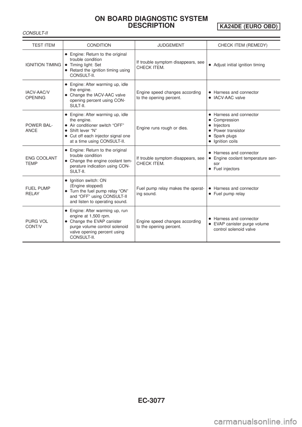
TEST ITEM CONDITION JUDGEMENT CHECK ITEM (REMEDY)
IGNITION TIMING+Engine: Return to the original
trouble condition
+Timing light: Set
+Retard the ignition timing using
CONSULT-II.If trouble symptom disappears, see
CHECK ITEM.+Adjust initial ignition timing
IACV-AAC/V
OPENING+Engine: After warming up, idle
the engine.
+Change the IACV-AAC valve
opening percent using CON-
SULT-II.Engine speed changes according
to the opening percent.+Harness and connector
+IACV-AAC valve
POWER BAL-
ANCE+Engine: After warming up, idle
the engine.
+Air conditioner switch ªOFFº
+Shift lever ªNº
+Cut off each injector signal one
at a time using CONSULT-II.Engine runs rough or dies.+Harness and connector
+Compression
+Injectors
+Power transistor
+Spark plugs
+Ignition coils
ENG COOLANT
TEMP+Engine: Return to the original
trouble condition
+Change the engine coolant tem-
perature indication using CON-
SULT-II.If trouble symptom disappears, see
CHECK ITEM.+Harness and connector
+Engine coolant temperature sen-
sor
+Fuel injectors
FUEL PUMP
RELAY+Ignition switch: ON
(Engine stopped)
+Turn the fuel pump relay ªONº
and ªOFFº using CONSULT-II
and listen to operating sound.Fuel pump relay makes the operat-
ing sound.+Harness and connector
+Fuel pump relay
PURG VOL
CONT/V+Engine: After warming up, run
engine at 1,500 rpm.
+Change the EVAP canister
purge volume control solenoid
valve opening percent using
CONSULT-II.Engine speed changes according
to the opening percent.+Harness and connector
+EVAP canister purge volume
control solenoid valve
ON BOARD DIAGNOSTIC SYSTEM
DESCRIPTION
KA24DE (EURO OBD)
CONSULT-II
EC-3077
Page 116 of 1306
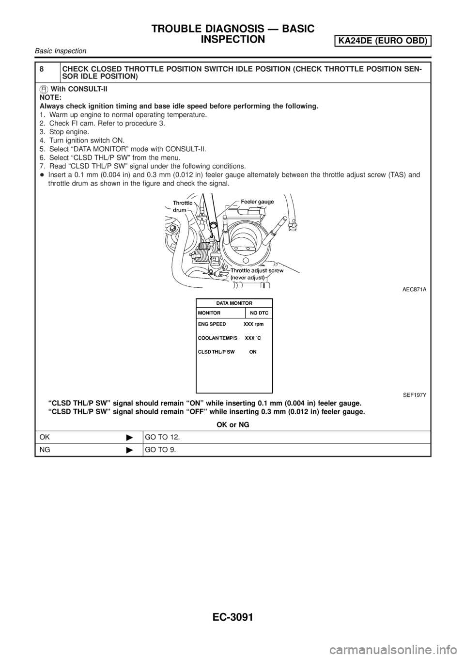
8 CHECK CLOSED THROTTLE POSITION SWITCH IDLE POSITION (CHECK THROTTLE POSITION SEN-
SOR IDLE POSITION)
With CONSULT-II
NOTE:
Always check ignition timing and base idle speed before performing the following.
1. Warm up engine to normal operating temperature.
2. Check FI cam. Refer to procedure 3.
3. Stop engine.
4. Turn ignition switch ON.
5. Select ªDATA MONITORº mode with CONSULT-II.
6. Select ªCLSD THL/P SWº from the menu.
7. Read ªCLSD THL/P SWº signal under the following conditions.
+Insert a 0.1 mm (0.004 in) and 0.3 mm (0.012 in) feeler gauge alternately between the throttle adjust screw (TAS) and
throttle drum as shown in the figure and check the signal.
AEC871A
SEF197Y
ªCLSD THL/P SWº signal should remain ªONº while inserting 0.1 mm (0.004 in) feeler gauge.
ªCLSD THL/P SWº signal should remain ªOFFº while inserting 0.3 mm (0.012 in) feeler gauge.
OK or NG
OK©GO TO 12.
NG©GO TO 9.
TROUBLE DIAGNOSIS Ð BASIC
INSPECTION
KA24DE (EURO OBD)
Basic Inspection
EC-3091
Page 117 of 1306
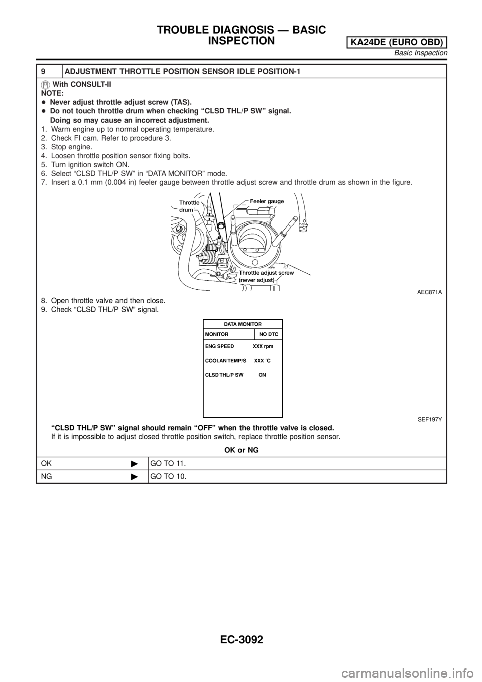
9 ADJUSTMENT THROTTLE POSITION SENSOR IDLE POSITION-1
With CONSULT-II
NOTE:
+Never adjust throttle adjust screw (TAS).
+Do not touch throttle drum when checking ªCLSD THL/P SWº signal.
Doing so may cause an incorrect adjustment.
1. Warm engine up to normal operating temperature.
2. Check FI cam. Refer to procedure 3.
3. Stop engine.
4. Loosen throttle position sensor fixing bolts.
5. Turn ignition switch ON.
6. Select ªCLSD THL/P SWº in ªDATA MONITORº mode.
7. Insert a 0.1 mm (0.004 in) feeler gauge between throttle adjust screw and throttle drum as shown in the figure.
AEC871A
8. Open throttle valve and then close.
9. Check ªCLSD THL/P SWº signal.
SEF197Y
ªCLSD THL/P SWº signal should remain ªOFFº when the throttle valve is closed.
If it is impossible to adjust closed throttle position switch, replace throttle position sensor.
OK or NG
OK©GO TO 11.
NG©GO TO 10.
TROUBLE DIAGNOSIS Ð BASIC
INSPECTION
KA24DE (EURO OBD)
Basic Inspection
EC-3092
Page 118 of 1306
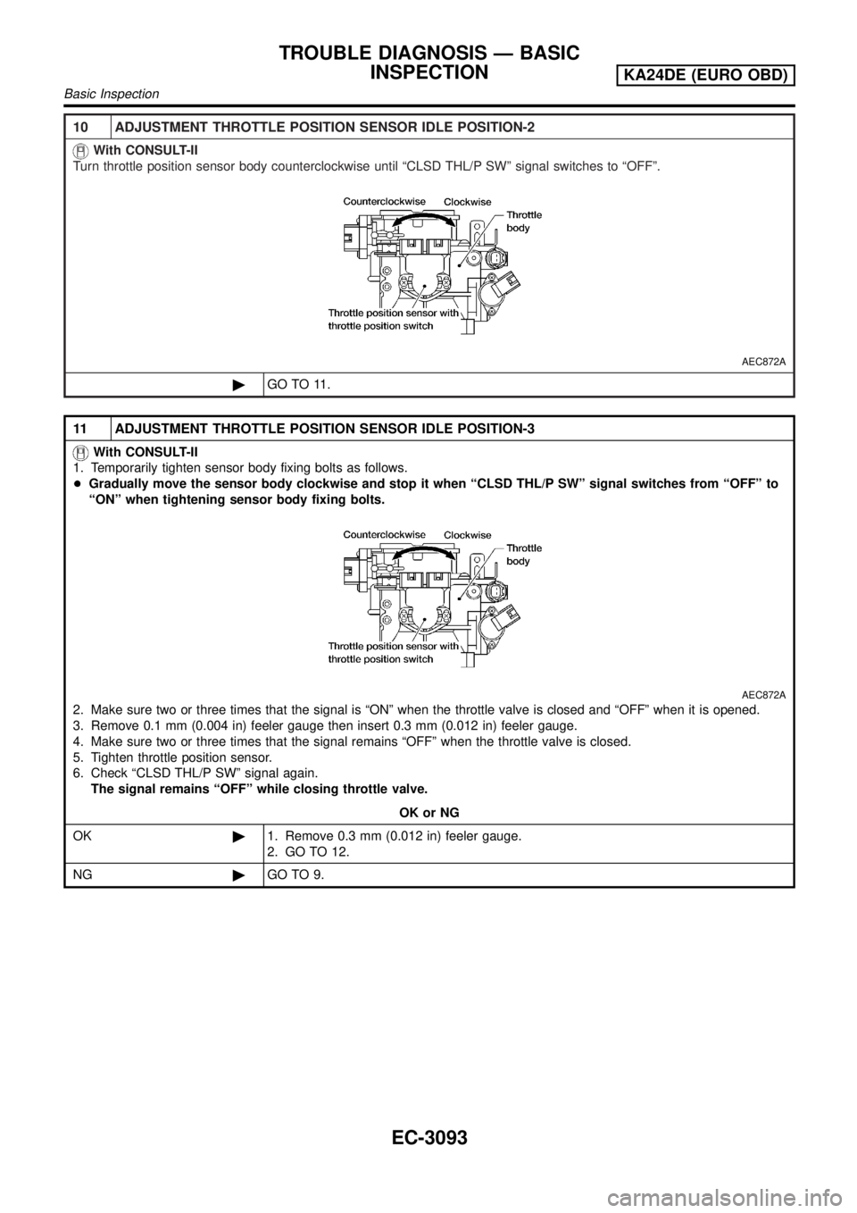
10 ADJUSTMENT THROTTLE POSITION SENSOR IDLE POSITION-2
With CONSULT-II
Turn throttle position sensor body counterclockwise until ªCLSD THL/P SWº signal switches to ªOFFº.
AEC872A
©GO TO 11.
11 ADJUSTMENT THROTTLE POSITION SENSOR IDLE POSITION-3
With CONSULT-II
1. Temporarily tighten sensor body fixing bolts as follows.
+Gradually move the sensor body clockwise and stop it when ªCLSD THL/P SWº signal switches from ªOFFº to
ªONº when tightening sensor body fixing bolts.
AEC872A
2. Make sure two or three times that the signal is ªONº when the throttle valve is closed and ªOFFº when it is opened.
3. Remove 0.1 mm (0.004 in) feeler gauge then insert 0.3 mm (0.012 in) feeler gauge.
4. Make sure two or three times that the signal remains ªOFFº when the throttle valve is closed.
5. Tighten throttle position sensor.
6. Check ªCLSD THL/P SWº signal again.
The signal remains ªOFFº while closing throttle valve.
OK or NG
OK©1. Remove 0.3 mm (0.012 in) feeler gauge.
2. GO TO 12.
NG©GO TO 9.
TROUBLE DIAGNOSIS Ð BASIC
INSPECTION
KA24DE (EURO OBD)
Basic Inspection
EC-3093
Page 128 of 1306
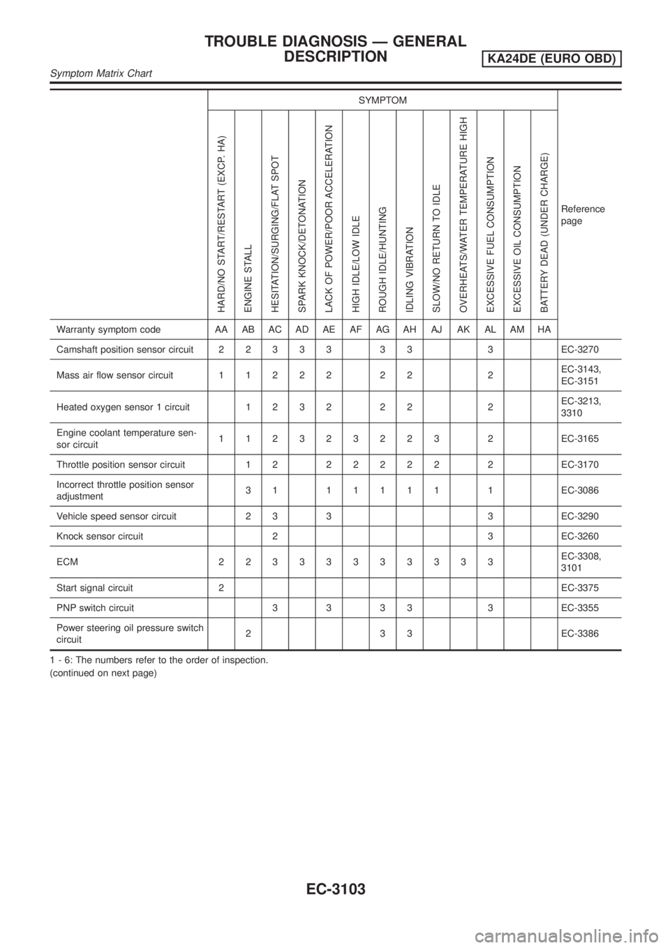
SYMPTOM
Reference
page
HARD/NO START/RESTART (EXCP. HA)
ENGINE STALL
HESITATION/SURGING/FLAT SPOT
SPARK KNOCK/DETONATION
LACK OF POWER/POOR ACCELERATION
HIGH IDLE/LOW IDLE
ROUGH IDLE/HUNTING
IDLING VIBRATION
SLOW/NO RETURN TO IDLE
OVERHEATS/WATER TEMPERATURE HIGH
EXCESSIVE FUEL CONSUMPTION
EXCESSIVE OIL CONSUMPTION
BATTERY DEAD (UNDER CHARGE)
Warranty symptom code AA AB AC AD AE AF AG AH AJ AK AL AM HA
Camshaft position sensor circuit22333 33 3EC-3270
Mass air flow sensor circuit11222 22 2EC-3143,
EC-3151
Heated oxygen sensor 1 circuit1232 22 2EC-3213,
3310
Engine coolant temperature sen-
sor circuit112323223 2EC-3165
Throttle position sensor circuit 1 222222 2EC-3170
Incorrect throttle position sensor
adjustment31 11111 1EC-3086
Vehicle speed sensor circuit 2 3 3 3 EC-3290
Knock sensor circuit 2 3 EC-3260
ECM 22333333333EC-3308,
3101
Start signal circuit 2EC-3375
PNP switch circuit 3 3 3 3 3 EC-3355
Power steering oil pressure switch
circuit2 3 3 EC-3386
1 - 6: The numbers refer to the order of inspection.
(continued on next page)
TROUBLE DIAGNOSIS Ð GENERAL
DESCRIPTION
KA24DE (EURO OBD)
Symptom Matrix Chart
EC-3103