2001 NISSAN PICK-UP turn signal
[x] Cancel search: turn signalPage 333 of 1306

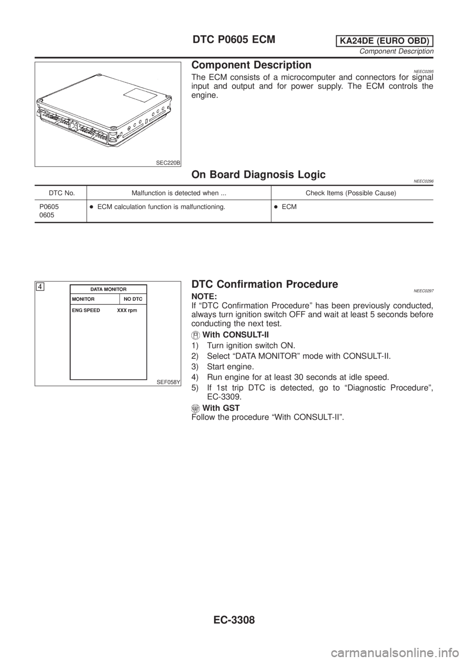
SEC220B
Component DescriptionNEEC0295The ECM consists of a microcomputer and connectors for signal
input and output and for power supply. The ECM controls the
engine.
On Board Diagnosis LogicNEEC0296
DTC No. Malfunction is detected when ... Check Items (Possible Cause)
P0605
0605+ECM calculation function is malfunctioning.+ECM
SEF058Y
DTC Confirmation ProcedureNEEC0297NOTE:
If ªDTC Confirmation Procedureº has been previously conducted,
always turn ignition switch OFF and wait at least 5 seconds before
conducting the next test.
With CONSULT-II
1) Turn ignition switch ON.
2) Select ªDATA MONITORº mode with CONSULT-II.
3) Start engine.
4) Run engine for at least 30 seconds at idle speed.
5) If 1st trip DTC is detected, go to ªDiagnostic Procedureº,
EC-3309.
With GST
Follow the procedure ªWith CONSULT-IIº.
DTC P0605 ECMKA24DE (EURO OBD)
Component Description
EC-3308
Page 337 of 1306

7) Make sure that ªOKº is displayed after touching ªSELF-DIAG
RESULTSº. If ªNGº is displayed, refer to ªDiagnostic
Procedureº, EC-3312.
AEC873A
Overall Function CheckNEEC0108Use this procedure to check the overall function of the heated oxy-
gen sensor 1 circuit. During this check, a 1st trip DTC might not be
confirmed.
Without CONSULT-II
1) Start engine and warm it up to normal operating temperature.
2) Set voltmeter probes between ECM terminal 50 (Heated oxy-
gen sensor 1 signal) and engine ground.
3) Check the following with engine speed held at 2,000 rpm con-
stant under no load.
+The maximum voltage is over 0.6V at least one time.
+The minimum voltage is over 0.1V at least one time.
4) If NG, go to ªDiagnostic Procedureº, EC-3312.
Diagnostic ProcedureNEEC0109
1 RETIGHTEN HEATED OXYGEN SENSOR 1
1. Turn ignition switch OFF.
2. Loosen and retighten heated oxygen sensor 1.
SEF332VC
Tightening torque:
40 - 60 N´m (4.1 - 6.1 kg-m, 30 - 44 ft-lb)
©GO TO 2.
DTC P1143 HO2S1KA24DE (EURO OBD)
DTC Confirmation Procedure
EC-3312
Page 344 of 1306

7) Make sure that ªOKº is displayed after touching ªSELF-DIAG
RESULTSº. If ªNGº is displayed, refer to ªDiagnostic
Procedureº, EC-3319.
AEC873A
Overall Function CheckNEEC0116Use this procedure to check the overall function of the front heated
oxygen sensor circuit. During this check, a 1st trip DTC might not
be confirmed.
Without CONSULT-II
1) Start engine and warm it up to normal operating temperature.
2) Set voltmeter probes between ECM terminal 50 (Heated oxy-
gen sensor 1 signal) and ECM ground.
3) Check the following with engine speed held at 2,000 rpm con-
stant under no load.
+The maximum voltage is below 0.8V at least one time.
+The minimum voltage is below 0.35V at least one time.
4) If NG, go to ªDiagnostic Procedureº, EC-3319.
Diagnostic ProcedureNEEC0117
1 RETIGHTEN HEATED OXYGEN SENSOR 1
1. Turn ignition switch OFF.
2. Loosen and retighten heated oxygen sensor 1.
SEF332VC
Tightening torque:
40 - 60 N´m (4.1 - 6.1 kg-m, 30 - 44 ft-lb)
©GO TO 2.
DTC P1144 HO2S1KA24DE (EURO OBD)
DTC Confirmation Procedure
EC-3319
Page 351 of 1306
![NISSAN PICK-UP 2001 Repair Manual PBIB0556E
Procedure for COND2NEEC0148S01021. While driving, release accelerator pedal completely from the
above condition [step 8] until ªINCOMPLETEº at ªCOND2º on
CONSULT-II screen has turned to NISSAN PICK-UP 2001 Repair Manual PBIB0556E
Procedure for COND2NEEC0148S01021. While driving, release accelerator pedal completely from the
above condition [step 8] until ªINCOMPLETEº at ªCOND2º on
CONSULT-II screen has turned to](/manual-img/5/57372/w960_57372-350.png)
PBIB0556E
Procedure for COND2NEEC0148S01021. While driving, release accelerator pedal completely from the
above condition [step 8] until ªINCOMPLETEº at ªCOND2º on
CONSULT-II screen has turned to ªCOMPLETEDº. (If will take
approximately 4 seconds.)
NOTE:
If ªCOMPLETEDº already appears at ªCOND3º on CONSULT-II
screen before ªProcedure for COND3º is conducted, it is
unnecessary to conduct step 1 in ªProcedure for COND3º.
SEC775C
Procedure for COND3NEEC0148S01031. Stop vehicle and let is idle until ªINCOMPLETEº of ªCOND3º
on CONSULT-II screen has turned to ªCOMPLETEDº. (It will
take a maximum of approximately 6 minutes.)
2. Make sure that ªOKº is displayed after touching ªSELF-DIAG
RESULTSº.
If ªNGº is displayed, refer to EC-3328, ªDiagnostic Procedureº.
AEC874A
Overall Function CheckNEEC0149Use this procedure to check the overall function of the heated oxy-
gen sensor 2 circuit. During this check, a 1st trip DTC might not be
confirmed.
CAUTION:
Always drive vehicle at a safe speed.
Without CONSULT-II
1) Start engine and drive vehicle at a speed of more than 70 km/h
(43 MPH) for 2 consecutive minutes.
2) Stop vehicle with engine running.
3) Set voltmeter probes between ECM terminals 56 (Heated oxy-
gen sensor 2 signal) and engine ground.
4) Check the voltage when revving engine up to 4,000 rpm under
no load at least 10 times.
(Depress and release accelerator pedal as soon as possible.)
The voltage should be below 0.54V at least once during
this procedure.
If the voltage can be confirmed in step 4, step 5 is not
necessary.
5) Keep vehicle at idling for 10 minutes, then check the voltage.
Or check the voltage when coasting from 80 km/h (50 MPH)
in 3rd gear position.
The voltage should be below 0.54V at least once during
this procedure.
6) If NG, go to ªDiagnostic Procedureº, EC-3328.
DTC P1146 HO2S2KA24DE (EURO OBD)
DTC Confirmation Procedure
EC-3326
Page 354 of 1306

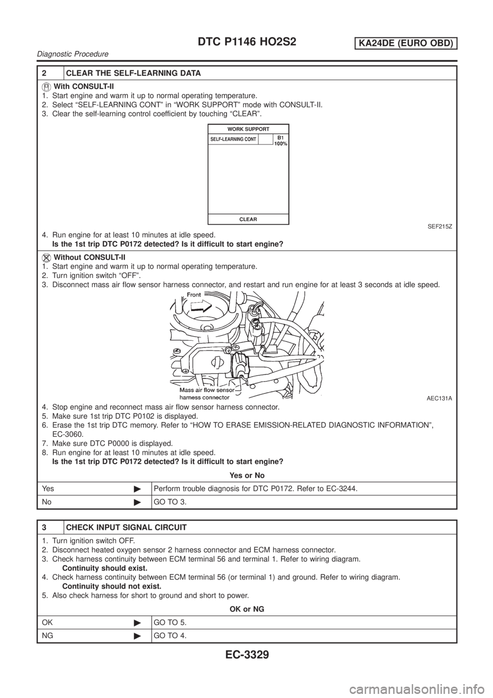
2 CLEAR THE SELF-LEARNING DATA
With CONSULT-II
1. Start engine and warm it up to normal operating temperature.
2. Select ªSELF-LEARNING CONTº in ªWORK SUPPORTº mode with CONSULT-II.
3. Clear the self-learning control coefficient by touching ªCLEARº.
SEF215Z
4. Run engine for at least 10 minutes at idle speed.
Is the 1st trip DTC P0172 detected? Is it difficult to start engine?
Without CONSULT-II
1. Start engine and warm it up to normal operating temperature.
2. Turn ignition switch ªOFFº.
3. Disconnect mass air flow sensor harness connector, and restart and run engine for at least 3 seconds at idle speed.
AEC131A
4. Stop engine and reconnect mass air flow sensor harness connector.
5. Make sure 1st trip DTC P0102 is displayed.
6. Erase the 1st trip DTC memory. Refer to ªHOW TO ERASE EMISSION-RELATED DIAGNOSTIC INFORMATIONº,
EC-3060.
7. Make sure DTC P0000 is displayed.
8. Run engine for at least 10 minutes at idle speed.
Is the 1st trip DTC P0172 detected? Is it difficult to start engine?
YesorNo
Ye s©Perform trouble diagnosis for DTC P0172. Refer to EC-3244.
No©GO TO 3.
3 CHECK INPUT SIGNAL CIRCUIT
1. Turn ignition switch OFF.
2. Disconnect heated oxygen sensor 2 harness connector and ECM harness connector.
3. Check harness continuity between ECM terminal 56 and terminal 1. Refer to wiring diagram.
Continuity should exist.
4. Check harness continuity between ECM terminal 56 (or terminal 1) and ground. Refer to wiring diagram.
Continuity should not exist.
5. Also check harness for short to ground and short to power.
OK or NG
OK©GO TO 5.
NG©GO TO 4.
DTC P1146 HO2S2KA24DE (EURO OBD)
Diagnostic Procedure
EC-3329
Page 357 of 1306

8 CHECK HEATED OXYGEN SENSOR 2
Without CONSULT-II
1. Reconnect all harness connectors disconnected.
2. Start engine and drive vehicle at a speed of more than 70 km/h (43 MPH) for 2 consecutive minutes.
3. Stop vehicle with engine running.
4. Set voltmeter probes between ECM terminals 56 (Heated oxygen sensor 2 signal) and engine ground.
AEC874A
5. Check the voltage when revving up to 4,000 rpm under no load at least 10 times.
(Depress and release accelerator pedal as soon as possible.)
The voltage should be above 0.56V at least once.
If the voltage is above 0.56V at step 4, step 5 is not necessary.
6. Check the voltage when revving up to 5,000 rpm under no load. Or keep vehicle at idling for 10 minutes, then check
the voltage. Or check the voltage when coasting from 80 km/h (50 MPH) in 3rd gear position (M/T), ªDº position with
ªODº OFF (A/T).
The voltage should be below 0.54V at least once.
CAUTION:
+Discard any heated oxygen sensor which has been dropped from a height of more than 0.5 m (19.7 in) onto
a hard surface such as a concrete floor; use a new one.
+Before installing new oxygen sensor, clean exhaust system threads using Oxygen Sensor Thread Cleaner
tool J-43897-18 or J-43897-12 and approved anti-seize lubricant.
OK or NG
OK©GO TO 9.
NG©Replace heated oxygen sensor 2.
9 CHECK SHIELD CIRCUIT
1. Turn ignition switch OFF.
2. Disconnect joint connector-3.
3. Check harness continuity between joint connector-3 terminal 1 and ground. Refer to wiring diagram.
Continuity should exist.
4. Also check harness for short to power.
5. Then reconnect harness connectors.
OK or NG
OK©GO TO 11.
NG©GO TO 10.
10 DETECT MALFUNCTIONING PART
Check the following.
+Joint connector-3 (Refer to ªHARNESS LAYOUTº, EL section.)
+Harness for open or short between joint connector-3 and engine ground
©Repair open circuit, short to power in harness or connectors.
DTC P1146 HO2S2KA24DE (EURO OBD)
Diagnostic Procedure
EC-3332
Page 361 of 1306
![NISSAN PICK-UP 2001 Repair Manual PBIB0558E
Procedure for COND2NEEC0157S01021. While driving, release accelerator pedal completely from the
above condition [step 8] until ªINCOMPLETEº at ªCOND2º on
CONSULT-II screen has turned to NISSAN PICK-UP 2001 Repair Manual PBIB0558E
Procedure for COND2NEEC0157S01021. While driving, release accelerator pedal completely from the
above condition [step 8] until ªINCOMPLETEº at ªCOND2º on
CONSULT-II screen has turned to](/manual-img/5/57372/w960_57372-360.png)
PBIB0558E
Procedure for COND2NEEC0157S01021. While driving, release accelerator pedal completely from the
above condition [step 8] until ªINCOMPLETEº at ªCOND2º on
CONSULT-II screen has turned to ªCOMPLETEDº. (If will take
approximately 4 seconds.)
NOTE:
If ªCOMPLETEDº already appears at ªCOND3º on CONSULT-II
screen before ªProcedure for COND3º is conducted, it is
unnecessary to conduct step 1 in ªProcedure for COND3º.
SEC778C
Procedure for COND3NEEC0157S01031. Stop vehicle and let is idle until ªINCOMPLETEº of ªCOND3º
on CONSULT-II screen has turned to ªCOMPLETEDº. (It will
take a maximum of approximately 6 minutes.)
2. Make sure that ªOKº is displayed after touching ªSELF-DIAG
RESULTSº.
If ªNGº is displayed, refer to EC-3338, ªDiagnostic Procedureº.
AEC874A
Overall Function CheckNEEC0158Use this procedure to check the overall function of the rear heated
oxygen sensor circuit. During this check, a 1st trip DTC might not
be confirmed.
CAUTION:
Always drive vehicle at a safe speed.
Without CONSULT-II
1) Start engine and drive vehicle at a speed of 70 km/h (43 MPH)
for 2 consecutive minutes.
2) Stop vehicle with engine running.
3) Set voltmeter probes between ECM terminals 56 (Heated oxy-
gen sensor 2 signal) and engine ground.
4) Check the voltage when revving engine up to 4,000 rpm under
no load at least 10 times.
(Depress and release accelerator pedal as soon as possible.)
The voltage should be above 0.56V at least once during
this procedure.
If the voltage can be confirmed in step 4, step 5 is not
necessary.
5) Keep vehicle at idling for 10 minutes, then check the voltage.
Or check the voltage when coasting from 80 km/h (50 MPH)
in 3rd gear position.
The voltage should be above 0.56V at least once during
this procedure.
6) If NG, go to ªDiagnostic Procedureº, EC-3338.
DTC P1147 HO2S2KA24DE (EURO OBD)
DTC Confirmation Procedure
EC-3336
Page 364 of 1306

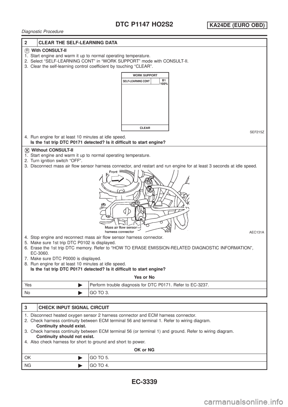
2 CLEAR THE SELF-LEARNING DATA
With CONSULT-II
1. Start engine and warm it up to normal operating temperature.
2. Select ªSELF-LEARNING CONTº in ªWORK SUPPORTº mode with CONSULT-II.
3. Clear the self-learning control coefficient by touching ªCLEARº.
SEF215Z
4. Run engine for at least 10 minutes at idle speed.
Is the 1st trip DTC P0171 detected? Is it difficult to start engine?
Without CONSULT-II
1. Start engine and warm it up to normal operating temperature.
2. Turn ignition switch ªOFFº.
3. Disconnect mass air flow sensor harness connector, and restart and run engine for at least 3 seconds at idle speed.
AEC131A
4. Stop engine and reconnect mass air flow sensor harness connector.
5. Make sure 1st trip DTC P0102 is displayed.
6. Erase the 1st trip DTC memory. Refer to ªHOW TO ERASE EMISSION-RELATED DIAGNOSTIC INFORMATIONº,
EC-3060.
7. Make sure DTC P0000 is displayed.
8. Run engine for at least 10 minutes at idle speed.
Is the 1st trip DTC P0171 detected? Is it difficult to start engine?
YesorNo
Ye s©Perform trouble diagnosis for DTC P0171. Refer to EC-3237.
No©GO TO 3.
3 CHECK INPUT SIGNAL CIRCUIT
1. Disconnect heated oxygen sensor 2 harness connector and ECM harness connector.
2. Check harness continuity between ECM terminal 56 and terminal 1. Refer to wiring diagram.
Continuity should exist.
3. Check harness continuity between ECM terminal 56 (or terminal 1) and ground. Refer to wiring diagram.
Continuity should not exist.
4. Also check harness for short to ground and short to power.
OK or NG
OK©GO TO 5.
NG©GO TO 4.
DTC P1147 HO2S2KA24DE (EURO OBD)
Diagnostic Procedure
EC-3339