Page 1837 of 3051

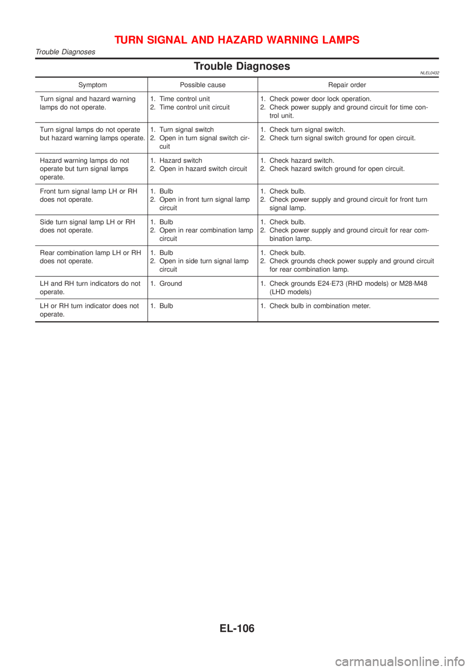
Trouble DiagnosesNLEL0432
Symptom Possible cause Repair order
Turn signal and hazard warning
lamps do not operate.1. Time control unit
2. Time control unit circuit1. Check power door lock operation.
2. Check power supply and ground circuit for time con-
trol unit.
Turn signal lamps do not operate
but hazard warning lamps operate.1. Turn signal switch
2. Open in turn signal switch cir-
cuit1. Check turn signal switch.
2. Check turn signal switch ground for open circuit.
Hazard warning lamps do not
operate but turn signal lamps
operate.1. Hazard switch
2. Open in hazard switch circuit1. Check hazard switch.
2. Check hazard switch ground for open circuit.
Front turn signal lamp LH or RH
does not operate.1. Bulb
2. Open in front turn signal lamp
circuit1. Check bulb.
2. Check power supply and ground circuit for front turn
signal lamp.
Side turn signal lamp LH or RH
does not operate.1. Bulb
2. Open in rear combination lamp
circuit1. Check bulb.
2. Check power supply and ground circuit for rear com-
bination lamp.
Rear combination lamp LH or RH
does not operate.1. Bulb
2. Open in side turn signal lamp
circuit1. Check bulb.
2. Check grounds check power supply and ground circuit
for rear combination lamp.
LH and RH turn indicators do not
operate.1. Ground 1. Check grounds E24´E73 (RHD models) or M28´M48
(LHD models)
LH or RH turn indicator does not
operate.1. Bulb 1. Check bulb in combination meter.
TURN SIGNAL AND HAZARD WARNING LAMPS
Trouble Diagnoses
EL-106
Page 1873 of 3051

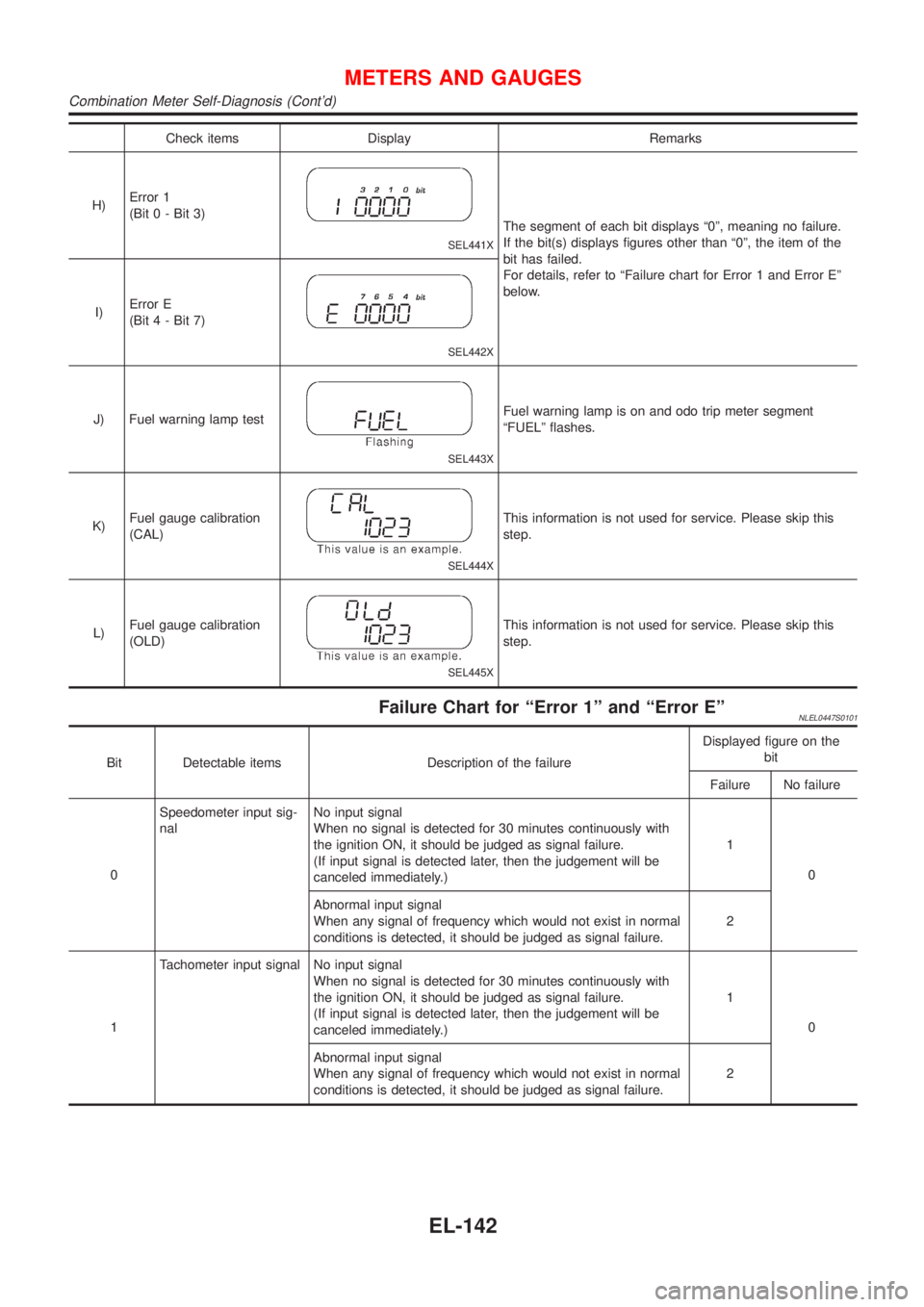
Check items Display Remarks
H)Error 1
(Bit 0 - Bit 3)
SEL441X
The segment of each bit displays ª0º, meaning no failure.
If the bit(s) displays figures other than ª0º, the item of the
bit has failed.
For details, refer to ªFailure chart for Error 1 and Error Eº
below.
I)Error E
(Bit 4 - Bit 7)
SEL442X
J) Fuel warning lamp test
SEL443X
Fuel warning lamp is on and odo trip meter segment
ªFUELº flashes.
K)Fuel gauge calibration
(CAL)
SEL444X
This information is not used for service. Please skip this
step.
L)Fuel gauge calibration
(OLD)
SEL445X
This information is not used for service. Please skip this
step.
Failure Chart for ªError 1º and ªError EºNLEL0447S0101
Bit Detectable items Description of the failureDisplayed figure on the
bit
Failure No failure
0Speedometer input sig-
nalNo input signal
When no signal is detected for 30 minutes continuously with
the ignition ON, it should be judged as signal failure.
(If input signal is detected later, then the judgement will be
canceled immediately.)1
0
Abnormal input signal
When any signal of frequency which would not exist in normal
conditions is detected, it should be judged as signal failure.2
1Tachometer input signal No input signal
When no signal is detected for 30 minutes continuously with
the ignition ON, it should be judged as signal failure.
(If input signal is detected later, then the judgement will be
canceled immediately.)1
0
Abnormal input signal
When any signal of frequency which would not exist in normal
conditions is detected, it should be judged as signal failure.2
METERS AND GAUGES
Combination Meter Self-Diagnosis (Cont'd)
EL-142
Page 1886 of 3051
SchematicNLEL0450
NEL786
WARNING LAMPS
Schematic
EL-155
Page 1887 of 3051
Wiring Diagram Ð WARN ÐNLEL0451MODELS WITH FUSE AND FUSIBLE LINK BOX E43NLEL0451S01
YEL897B
WARNING LAMPS
Wiring Diagram Ð WARN Ð
EL-156
Page 1888 of 3051
YEL898B
WARNING LAMPS
Wiring Diagram Ð WARN Ð (Cont'd)
EL-157
Page 1889 of 3051
YEL899B
WARNING LAMPS
Wiring Diagram Ð WARN Ð (Cont'd)
EL-158
Page 1890 of 3051
YEL900B
WARNING LAMPS
Wiring Diagram Ð WARN Ð (Cont'd)
EL-159
Page 1891 of 3051
MODELS WITH FUSE AND FUSIBLE LINK BOX E90NLEL0451S02
YEL422C
WARNING LAMPS
Wiring Diagram Ð WARN Ð (Cont'd)
EL-160