2001 NISSAN ALMERA TINO brake sensor
[x] Cancel search: brake sensorPage 18 of 3051
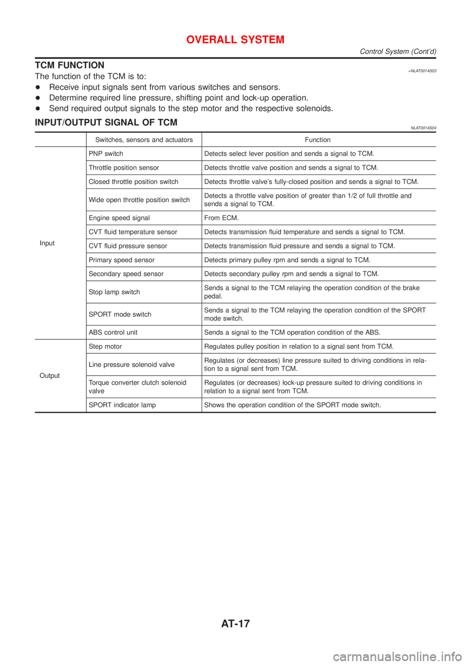
TCM FUNCTION=NLAT0014S03The function of the TCM is to:
+Receive input signals sent from various switches and sensors.
+Determine required line pressure, shifting point and lock-up operation.
+Send required output signals to the step motor and the respective solenoids.
INPUT/OUTPUT SIGNAL OF TCMNLAT0014S04
Switches, sensors and actuators Function
InputPNP switch Detects select lever position and sends a signal to TCM.
Throttle position sensor Detects throttle valve position and sends a signal to TCM.
Closed throttle position switch Detects throttle valve's fully-closed position and sends a signal to TCM.
Wide open throttle position switchDetects a throttle valve position of greater than 1/2 of full throttle and
sends a signal to TCM.
Engine speed signal From ECM.
CVT fluid temperature sensor Detects transmission fluid temperature and sends a signal to TCM.
CVT fluid pressure sensor Detects transmission fluid pressure and sends a signal to TCM.
Primary speed sensor Detects primary pulley rpm and sends a signal to TCM.
Secondary speed sensor Detects secondary pulley rpm and sends a signal to TCM.
Stop lamp switchSends a signal to the TCM relaying the operation condition of the brake
pedal.
SPORT mode switchSends a signal to the TCM relaying the operation condition of the SPORT
mode switch.
ABS control unit Sends a signal to the TCM operation condition of the ABS.
OutputStep motor Regulates pulley position in relation to a signal sent from TCM.
Line pressure solenoid valveRegulates (or decreases) line pressure suited to driving conditions in rela-
tion to a signal sent from TCM.
Torque converter clutch solenoid
valveRegulates (or decreases) lock-up pressure suited to driving conditions in
relation to a signal sent from TCM.
SPORT indicator lamp Shows the operation condition of the SPORT mode switch.
OVERALL SYSTEM
Control System (Cont'd)
AT-17
Page 26 of 3051
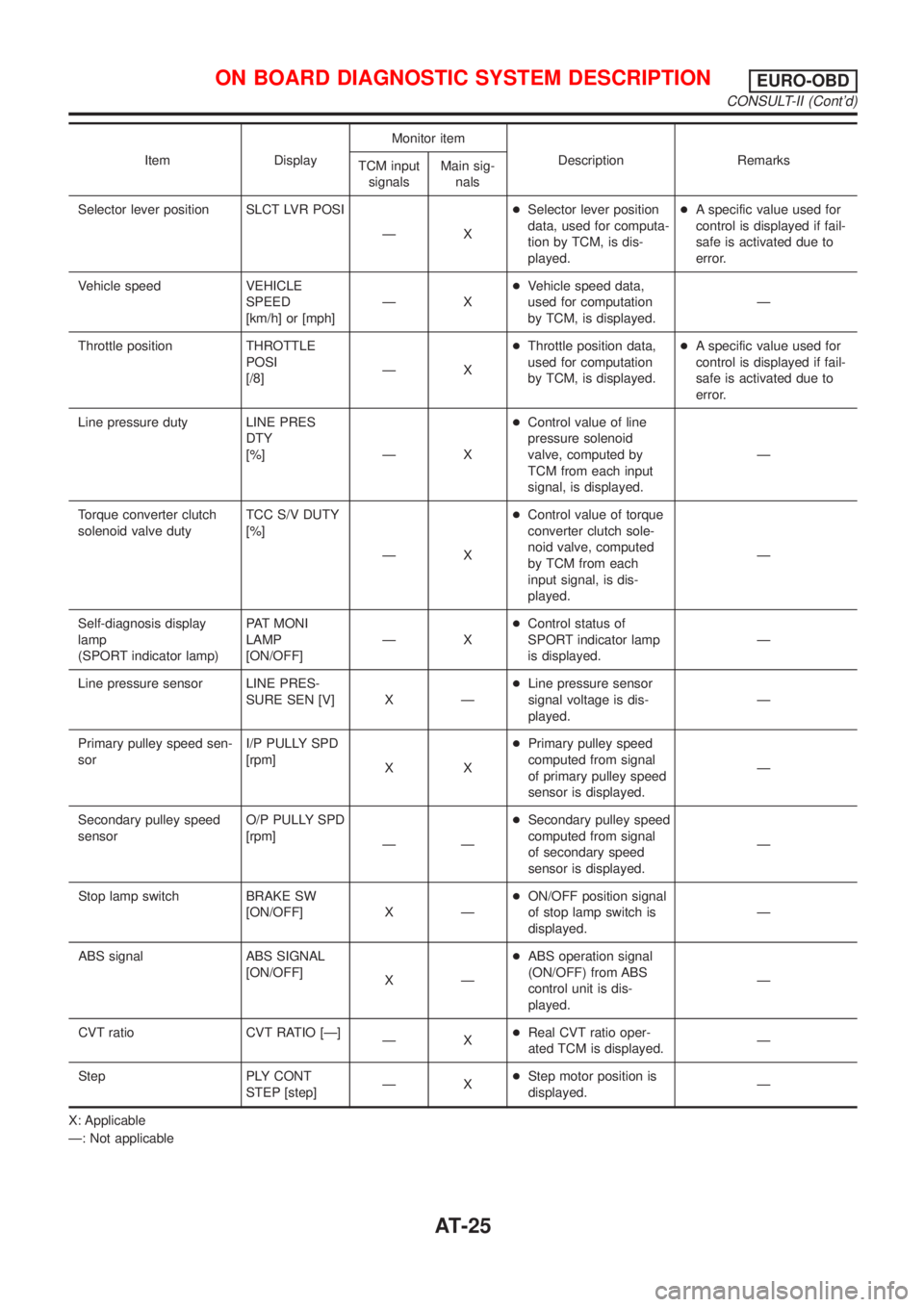
Item DisplayMonitor item
Description Remarks
TCM input
signalsMain sig-
nals
Selector lever position SLCT LVR POSI
ÐX+Selector lever position
data, used for computa-
tion by TCM, is dis-
played.+A specific value used for
control is displayed if fail-
safe is activated due to
error.
Vehicle speed VEHICLE
SPEED
[km/h] or [mph]ÐX+Vehicle speed data,
used for computation
by TCM, is displayed.Ð
Throttle position THROTTLE
POSI
[/8]ÐX+Throttle position data,
used for computation
by TCM, is displayed.+A specific value used for
control is displayed if fail-
safe is activated due to
error.
Line pressure duty LINE PRES
DTY
[%] Ð X+Control value of line
pressure solenoid
valve, computed by
TCM from each input
signal, is displayed.Ð
Torque converter clutch
solenoid valve dutyTCC S/V DUTY
[%]
ÐX+Control value of torque
converter clutch sole-
noid valve, computed
by TCM from each
input signal, is dis-
played.Ð
Self-diagnosis display
lamp
(SPORT indicator lamp)PAT MONI
LAMP
[ON/OFF]ÐX+Control status of
SPORT indicator lamp
is displayed.Ð
Line pressure sensor LINE PRES-
SURE SEN [V] X Ð+Line pressure sensor
signal voltage is dis-
played.Ð
Primary pulley speed sen-
sorI/P PULLY SPD
[rpm]
XX+Primary pulley speed
computed from signal
of primary pulley speed
sensor is displayed.Ð
Secondary pulley speed
sensorO/P PULLY SPD
[rpm]
ÐÐ+Secondary pulley speed
computed from signal
of secondary speed
sensor is displayed.Ð
Stop lamp switch BRAKE SW
[ON/OFF] X Ð+ON/OFF position signal
of stop lamp switch is
displayed.Ð
ABS signal ABS SIGNAL
[ON/OFF]
XÐ+ABS operation signal
(ON/OFF) from ABS
control unit is dis-
played.Ð
CVT ratio CVT RATIO [Ð]
ÐX+Real CVT ratio oper-
ated TCM is displayed.Ð
Step PLY CONT
STEP [step]ÐX+Step motor position is
displayed.Ð
X: Applicable
Ð: Not applicable
ON BOARD DIAGNOSTIC SYSTEM DESCRIPTIONEURO-OBD
CONSULT-II (Cont'd)
AT-25
Page 29 of 3051
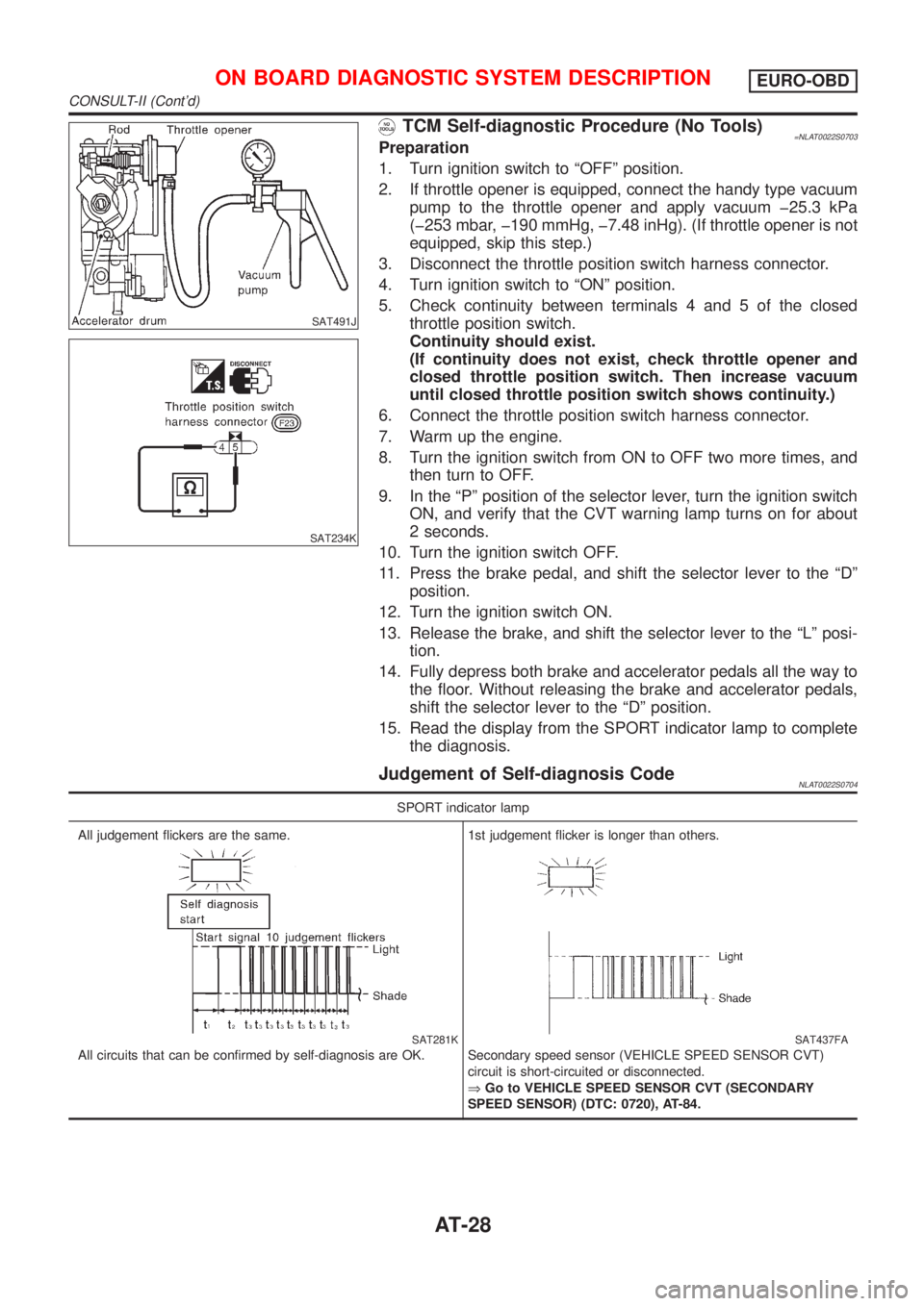
SAT491J
SAT234K
TCM Self-diagnostic Procedure (No Tools)=NLAT0022S0703Preparation
1. Turn ignition switch to ªOFFº position.
2. If throttle opener is equipped, connect the handy type vacuum
pump to the throttle opener and apply vacuum þ25.3 kPa
(þ253 mbar, þ190 mmHg, þ7.48 inHg). (If throttle opener is not
equipped, skip this step.)
3. Disconnect the throttle position switch harness connector.
4. Turn ignition switch to ªONº position.
5. Check continuity between terminals 4 and 5 of the closed
throttle position switch.
Continuity should exist.
(If continuity does not exist, check throttle opener and
closed throttle position switch. Then increase vacuum
until closed throttle position switch shows continuity.)
6. Connect the throttle position switch harness connector.
7. Warm up the engine.
8. Turn the ignition switch from ON to OFF two more times, and
then turn to OFF.
9. In the ªPº position of the selector lever, turn the ignition switch
ON, and verify that the CVT warning lamp turns on for about
2 seconds.
10. Turn the ignition switch OFF.
11. Press the brake pedal, and shift the selector lever to the ªDº
position.
12. Turn the ignition switch ON.
13. Release the brake, and shift the selector lever to the ªLº posi-
tion.
14. Fully depress both brake and accelerator pedals all the way to
the floor. Without releasing the brake and accelerator pedals,
shift the selector lever to the ªDº position.
15. Read the display from the SPORT indicator lamp to complete
the diagnosis.
Judgement of Self-diagnosis CodeNLAT0022S0704
SPORT indicator lamp
All judgement flickers are the same.
SAT281K
All circuits that can be confirmed by self-diagnosis are OK.1st judgement flicker is longer than others.
SAT437FA
Secondary speed sensor (VEHICLE SPEED SENSOR CVT)
circuit is short-circuited or disconnected.
ÞGo to VEHICLE SPEED SENSOR CVT (SECONDARY
SPEED SENSOR) (DTC: 0720), AT-84.
ON BOARD DIAGNOSTIC SYSTEM DESCRIPTIONEURO-OBD
CONSULT-II (Cont'd)
AT-28
Page 35 of 3051
![NISSAN ALMERA TINO 2001 Service Repair Manual Item DisplayMonitor item
Description Remarks
TCM input
signalsMain sig-
nals
Line pressure sensor LINE PRES
SEN [V] X Ð+CVT fluid pressure sen-
sor signal voltage is
displayed.Ð
Primary pulley speed NISSAN ALMERA TINO 2001 Service Repair Manual Item DisplayMonitor item
Description Remarks
TCM input
signalsMain sig-
nals
Line pressure sensor LINE PRES
SEN [V] X Ð+CVT fluid pressure sen-
sor signal voltage is
displayed.Ð
Primary pulley speed](/manual-img/5/57352/w960_57352-34.png)
Item DisplayMonitor item
Description Remarks
TCM input
signalsMain sig-
nals
Line pressure sensor LINE PRES
SEN [V] X Ð+CVT fluid pressure sen-
sor signal voltage is
displayed.Ð
Primary pulley speed sen-
sorI/P PULLY SPD
[rpm]
XX+Primary pulley speed
computed from signal
of primary pulley speed
sensor is displayed.
Secondary pulley speed
sensorO/P PULLY SPD
[rpm]
ÐÐ+Secondary pulley speed
computed from signal
of secondary speed
sensor is displayed.Ð
Stop lamp switch BRAKE SW
[ON/OFF] X Ð+ON/OFF position signal
of stop lamp switch is
displayed.Ð
ABS signal ABS SIGNAL
[ON/OFF]
XÐ+ABS operation signal
(ON/OFF) from ABS
control unit is dis-
played.Ð
CVT ratio CVT RATIO [Ð]
ÐX+Real CVT ratio oper-
ated TCM is displayed.Ð
Step PLY CONT
STEP [step]ÐX+Step motor position is
displayed.Ð
X: Applicable
Ð: Not applicable
SAT250K
HOW TO ERASE SELF-DIAGNOSTIC RESULTS
(
WITH CONSULT-II)NLAT0245S091. If the ignition switch stays ªONº after repair work, be sure to
turn ignition switch ªOFFº once. Wait for at least 3 seconds and
then turn it ªONº again.
2. Turn CONSULT-II ªONº, and touch ªCVTº.
SAT252K
3. Touch ªSELF-DIAG RESULTSº.
ON BOARD DIAGNOSTIC SYSTEM
DESCRIPTION
EXCEPT FOR EURO-OBD
CONSULT-II (Cont'd)
AT-34
Page 44 of 3051
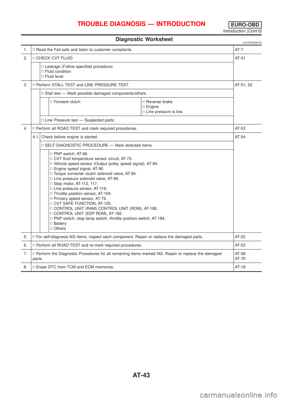
Diagnostic Worksheet=NLAT0023S0102
1.NRead the Fail-safe and listen to customer complaints. AT-7
2.NCHECK CVT FLUIDAT-51
NLeakage (Follow specified procedure)
NFluid condition
NFluid level
3.NPerform STALL TEST and LINE PRESSURE TEST. AT-51, 52
NStall test Ð Mark possible damaged components/others.
NForward clutchNReverse brake
NEngine
NLine pressure is low.
NLine Pressure test Ð Suspected parts:
4.NPerform all ROAD TEST and mark required procedures. AT-53
4-1. Check before engine is started.AT-54
NSELF-DIAGNOSTIC PROCEDURE Ð Mark detected items.
NPNP switch, AT-66.
NCVT fluid temperature sensor circuit, AT-73.
NVehicle speed sensor (Output pulley speed signal), AT-84.
NEngine speed signal, AT-90.
NTorque converter clutch solenoid valve, AT-94.
NLine pressure solenoid valve, AT-99.
NStep motor, AT-112, 117.
NLine pressure sensor, AT-119.
NThrottle position sensor, AT-104.
NPrimary speed sensor, AT-79.
NCVT SAFE FUNCTION, AT-125.
NCONTROL UNIT (RAM) CONTROL UNIT (ROM), AT-180.
NCONTROL UNIT (EEP ROM), AT-182.
NPNP switch, stop lamp switch, throttle position switch, AT-184.
NBattery
NOthers
5.NFor self-diagnosis NG items, inspect each component. Repair or replace the damaged parts. AT-22
6.NPerform all ROAD TEST and re-mark required procedures. AT-53
7.NPerform the Diagnostic Procedures for all remaining items marked NG. Repair or replace the damaged
parts.AT-58
AT-70
8.NErase DTC from TCM and ECM memories. AT-19
TROUBLE DIAGNOSIS Ð INTRODUCTIONEURO-OBD
Introduction (Cont'd)
AT-43
Page 49 of 3051
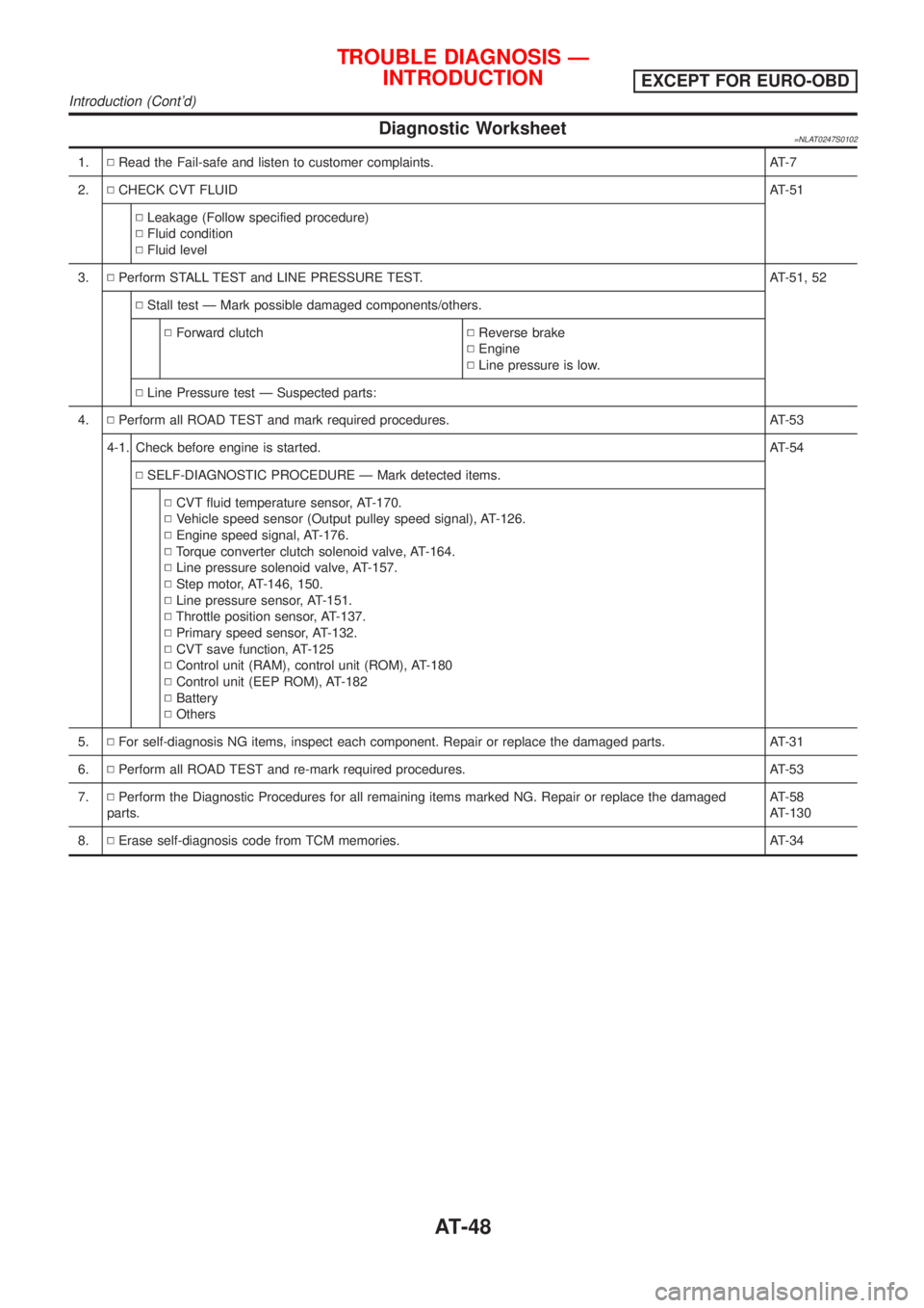
Diagnostic Worksheet=NLAT0247S0102
1.NRead the Fail-safe and listen to customer complaints. AT-7
2.NCHECK CVT FLUIDAT-51
NLeakage (Follow specified procedure)
NFluid condition
NFluid level
3.NPerform STALL TEST and LINE PRESSURE TEST. AT-51, 52
NStall test Ð Mark possible damaged components/others.
NForward clutchNReverse brake
NEngine
NLine pressure is low.
NLine Pressure test Ð Suspected parts:
4.NPerform all ROAD TEST and mark required procedures. AT-53
4-1. Check before engine is started.AT-54
NSELF-DIAGNOSTIC PROCEDURE Ð Mark detected items.
NCVT fluid temperature sensor, AT-170.
NVehicle speed sensor (Output pulley speed signal), AT-126.
NEngine speed signal, AT-176.
NTorque converter clutch solenoid valve, AT-164.
NLine pressure solenoid valve, AT-157.
NStep motor, AT-146, 150.
NLine pressure sensor, AT-151.
NThrottle position sensor, AT-137.
NPrimary speed sensor, AT-132.
NCVT save function, AT-125
NControl unit (RAM), control unit (ROM), AT-180
NControl unit (EEP ROM), AT-182
NBattery
NOthers
5.NFor self-diagnosis NG items, inspect each component. Repair or replace the damaged parts. AT-31
6.NPerform all ROAD TEST and re-mark required procedures. AT-53
7.NPerform the Diagnostic Procedures for all remaining items marked NG. Repair or replace the damaged
parts.AT-58
AT-130
8.NErase self-diagnosis code from TCM memories. AT-34
TROUBLE DIAGNOSIS Ð
INTRODUCTION
EXCEPT FOR EURO-OBD
Introduction (Cont'd)
AT-48
Page 216 of 3051

Wheel Hub and Knuckle
COMPONENTS=NLAX0008
NAX006
1. Drive shaft
2. Knuckle
3. Baffle plate (where fitted)
4. ABS sensor5. Wheel bearing assembly
6. Snap ring
7. Hub bolt
8. Wheel hub9. Wheel bearing lock nut
10. Cotter pin
11. Brake disc
12. Wheel nut
REMOVALNLAX0009CAUTION:
Before removing the front axle assembly, disconnect the ABS
wheel sensor from the assembly. Then move it away from the
front axle assembly area.
Failure to do so may result in damage to the sensor wires and
the sensor becoming inoperative.
SFA090A
1. Remove wheel bearing lock nut.
FRONT AXLE
Wheel Hub and Knuckle
AX-5
Page 232 of 3051

SBR686C
Precautions
PRECAUTIONSNLAX0022+When installing each rubber part, final tightening must be
carried out under unladen condition* with tires on ground.
*: Fuel, radiator coolant and engine oil full. Spare tire, jack,
hand tools and mats in designated positions.
+Use flare nut wrench when removing or installing brake
tubes.
+After installing removed suspension parts, check wheel
alignment.
+Do not jack up at the trailing arm and lateral link.
+Always torque brake lines when installing.
Preparation
SPECIAL SERVICE TOOLSNLAX0032
Tool number
Tool nameDescription
KV40104710
Drift
NT474
Install ABS sensor rotor
a: 76.3 mm (3.004 in) dia.
b: 67.9 mm (2.673 in) dia.
ST3072000
Drift
NT115
Install ABS sensor rotor
a: 77 mm (3.03 in) dia.
b: 55.5 mm (2.185 in) dia.
COMMERCIAL SERVICE TOOLSNLAX0024
Tool name Description
1 Flare nut crowfoot
2 Torque wrench
NT360
Removing and installing brake piping
a: 10 mm (0.39 in)
REAR AXLE
Precautions
AX-21