2001 NISSAN ALMERA TINO load capacity
[x] Cancel search: load capacityPage 2723 of 3051
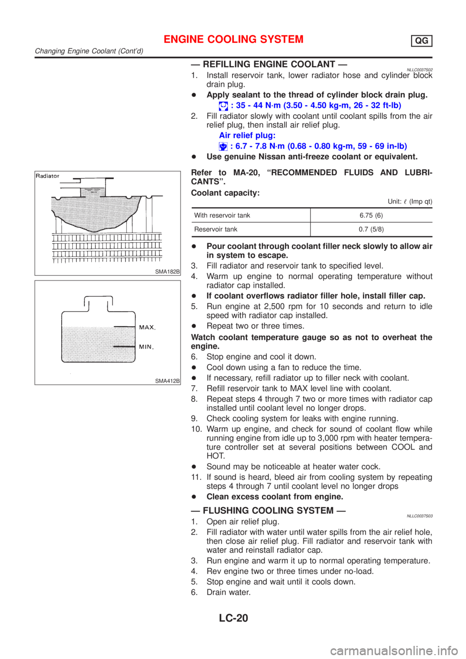
Ð REFILLING ENGINE COOLANT ÐNLLC0037S021. Install reservoir tank, lower radiator hose and cylinder block
drain plug.
+Apply sealant to the thread of cylinder block drain plug.
: 35 - 44 N´m (3.50 - 4.50 kg-m, 26 - 32 ft-lb)
2. Fill radiator slowly with coolant until coolant spills from the air
relief plug, then install air relief plug.
Air relief plug:
: 6.7 - 7.8 N´m (0.68 - 0.80 kg-m, 59 - 69 in-lb)
+Use genuine Nissan anti-freeze coolant or equivalent.
SMA182B
SMA412B
Refer to MA-20, ªRECOMMENDED FLUIDS AND LUBRI-
CANTSº.
Coolant capacity:
Unit:!(Imp qt)
With reservoir tank 6.75 (6)
Reservoir tank 0.7 (5/8)
+Pour coolant through coolant filler neck slowly to allow air
in system to escape.
3. Fill radiator and reservoir tank to specified level.
4. Warm up engine to normal operating temperature without
radiator cap installed.
+If coolant overflows radiator filler hole, install filler cap.
5. Run engine at 2,500 rpm for 10 seconds and return to idle
speed with radiator cap installed.
+Repeat two or three times.
Watch coolant temperature gauge so as not to overheat the
engine.
6. Stop engine and cool it down.
+Cool down using a fan to reduce the time.
+If necessary, refill radiator up to filler neck with coolant.
7. Refill reservoir tank to MAX level line with coolant.
8. Repeat steps 4 through 7 two or more times with radiator cap
installed until coolant level no longer drops.
9. Check cooling system for leaks with engine running.
10. Warm up engine, and check for sound of coolant flow while
running engine from idle up to 3,000 rpm with heater tempera-
ture controller set at several positions between COOL and
HOT.
+Sound may be noticeable at heater water cock.
11. If sound is heard, bleed air from cooling system by repeating
steps 4 through 7 until coolant level no longer drops
+Clean excess coolant from engine.
Ð FLUSHING COOLING SYSTEM ÐNLLC0037S031. Open air relief plug.
2. Fill radiator with water until water spills from the air relief hole,
then close air relief plug. Fill radiator and reservoir tank with
water and reinstall radiator cap.
3. Run engine and warm it up to normal operating temperature.
4. Rev engine two or three times under no-load.
5. Stop engine and wait until it cools down.
6. Drain water.
ENGINE COOLING SYSTEMQG
Changing Engine Coolant (Cont'd)
LC-20
Page 2725 of 3051
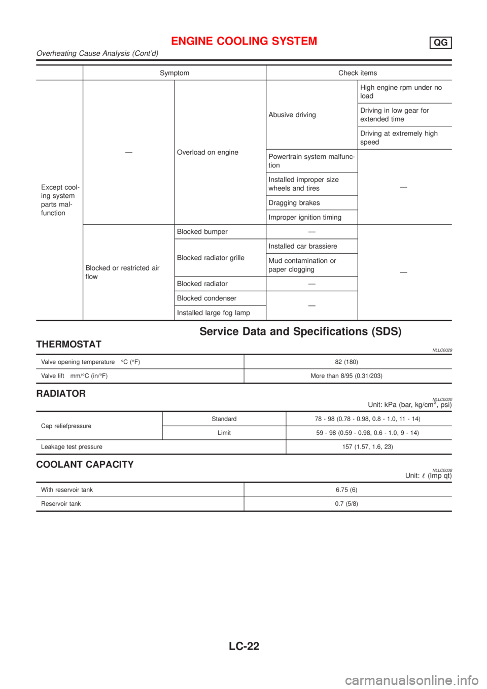
Symptom Check items
Except cool-
ing system
parts mal-
functionÐ Overload on engineAbusive drivingHigh engine rpm under no
load
Driving in low gear for
extended time
Driving at extremely high
speed
Powertrain system malfunc-
tion
Ð Installed improper size
wheels and tires
Dragging brakes
Improper ignition timing
Blocked or restricted air
flowBlocked bumper Ð
Ð Blocked radiator grilleInstalled car brassiere
Mud contamination or
paper clogging
Blocked radiator Ð
Blocked condenser
Ð
Installed large fog lamp
Service Data and Specifications (SDS)
THERMOSTATNLLC0029
Valve opening temperature ÉC (ÉF) 82 (180)
Valve lift mm/ÉC (in/ÉF)More than 8/95 (0.31/203)
RADIATORNLLC0030Unit: kPa (bar, kg/cm2, psi)
Cap reliefpressureStandard 78 - 98 (0.78 - 0.98, 0.8 - 1.0, 11 - 14)
Limit 59 - 98 (0.59 - 0.98, 0.6 - 1.0,9-14)
Leakage test pressure157 (1.57, 1.6, 23)
COOLANT CAPACITYNLLC0038Unit:!(Imp qt)
With reservoir tank6.75 (6)
Reservoir tank0.7 (5/8)
ENGINE COOLING SYSTEMQG
Overheating Cause Analysis (Cont'd)
LC-22
Page 2742 of 3051
SMA182B
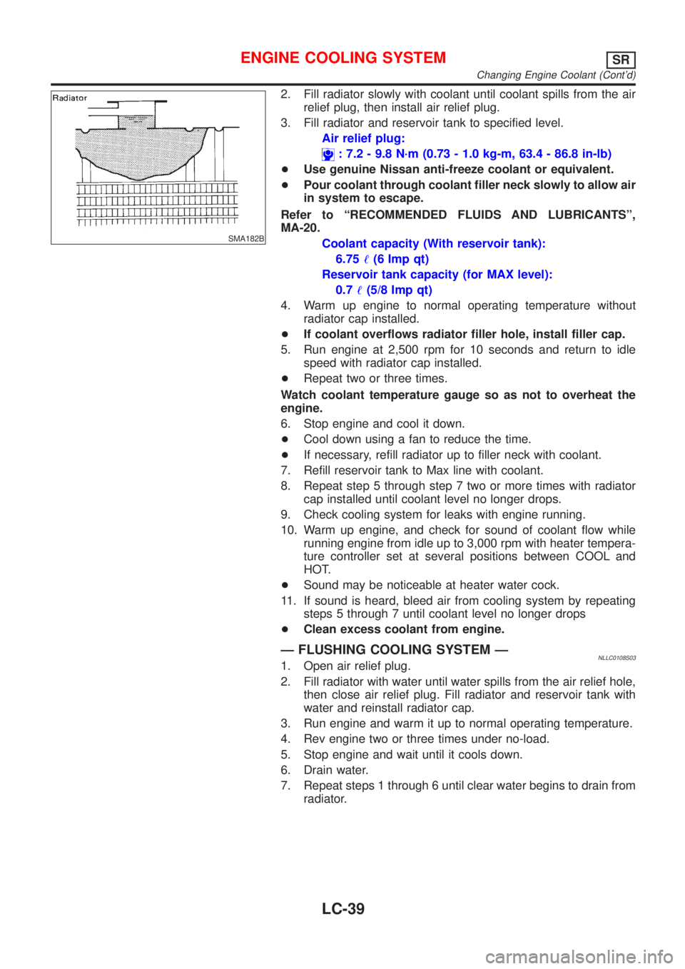
2. Fill radiator slowly with coolant until coolant spills from the air
relief plug, then install air relief plug.
3. Fill radiator and reservoir tank to specified level.
Air relief plug:
: 7.2 - 9.8 N´m (0.73 - 1.0 kg-m, 63.4 - 86.8 in-lb)
+Use genuine Nissan anti-freeze coolant or equivalent.
+Pour coolant through coolant filler neck slowly to allow air
in system to escape.
Refer to ªRECOMMENDED FLUIDS AND LUBRICANTSº,
MA-20.
Coolant capacity (With reservoir tank):
6.75!(6 Imp qt)
Reservoir tank capacity (for MAX level):
0.7!(5/8 Imp qt)
4. Warm up engine to normal operating temperature without
radiator cap installed.
+If coolant overflows radiator filler hole, install filler cap.
5. Run engine at 2,500 rpm for 10 seconds and return to idle
speed with radiator cap installed.
+Repeat two or three times.
Watch coolant temperature gauge so as not to overheat the
engine.
6. Stop engine and cool it down.
+Cool down using a fan to reduce the time.
+If necessary, refill radiator up to filler neck with coolant.
7. Refill reservoir tank to Max line with coolant.
8. Repeat step 5 through step 7 two or more times with radiator
cap installed until coolant level no longer drops.
9. Check cooling system for leaks with engine running.
10. Warm up engine, and check for sound of coolant flow while
running engine from idle up to 3,000 rpm with heater tempera-
ture controller set at several positions between COOL and
HOT.
+Sound may be noticeable at heater water cock.
11. If sound is heard, bleed air from cooling system by repeating
steps 5 through 7 until coolant level no longer drops
+Clean excess coolant from engine.
Ð FLUSHING COOLING SYSTEM ÐNLLC0108S031. Open air relief plug.
2. Fill radiator with water until water spills from the air relief hole,
then close air relief plug. Fill radiator and reservoir tank with
water and reinstall radiator cap.
3. Run engine and warm it up to normal operating temperature.
4. Rev engine two or three times under no-load.
5. Stop engine and wait until it cools down.
6. Drain water.
7. Repeat steps 1 through 6 until clear water begins to drain from
radiator.
ENGINE COOLING SYSTEMSR
Changing Engine Coolant (Cont'd)
LC-39
Page 2744 of 3051
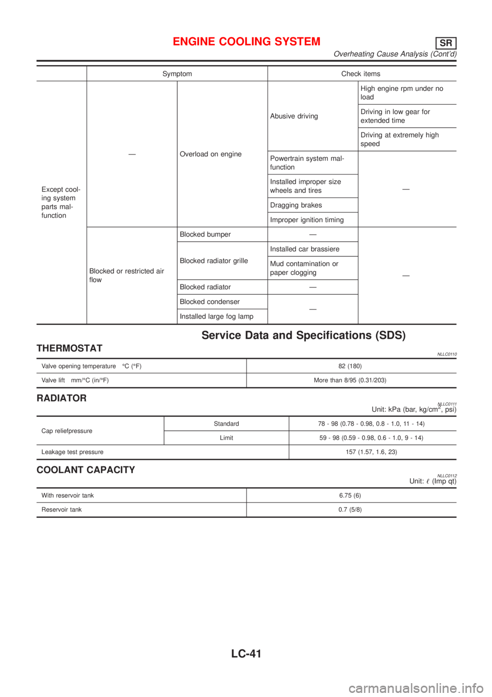
Symptom Check items
Except cool-
ing system
parts mal-
functionÐ Overload on engineAbusive drivingHigh engine rpm under no
load
Driving in low gear for
extended time
Driving at extremely high
speed
Powertrain system mal-
function
Ð Installed improper size
wheels and tires
Dragging brakes
Improper ignition timing
Blocked or restricted air
flowBlocked bumper Ð
Ð Blocked radiator grilleInstalled car brassiere
Mud contamination or
paper clogging
Blocked radiator Ð
Blocked condenser
Ð
Installed large fog lamp
Service Data and Specifications (SDS)
THERMOSTATNLLC0110
Valve opening temperature ÉC (ÉF) 82 (180)
Valve lift mm/ÉC (in/ÉF)More than 8/95 (0.31/203)
RADIATORNLLC0111Unit: kPa (bar, kg/cm2, psi)
Cap reliefpressureStandard 78 - 98 (0.78 - 0.98, 0.8 - 1.0, 11 - 14)
Limit 59 - 98 (0.59 - 0.98, 0.6 - 1.0,9-14)
Leakage test pressure157 (1.57, 1.6, 23)
COOLANT CAPACITYNLLC0112Unit:!(Imp qt)
With reservoir tank6.75 (6)
Reservoir tank0.7 (5/8)
ENGINE COOLING SYSTEMSR
Overheating Cause Analysis (Cont'd)
LC-41
Page 2764 of 3051
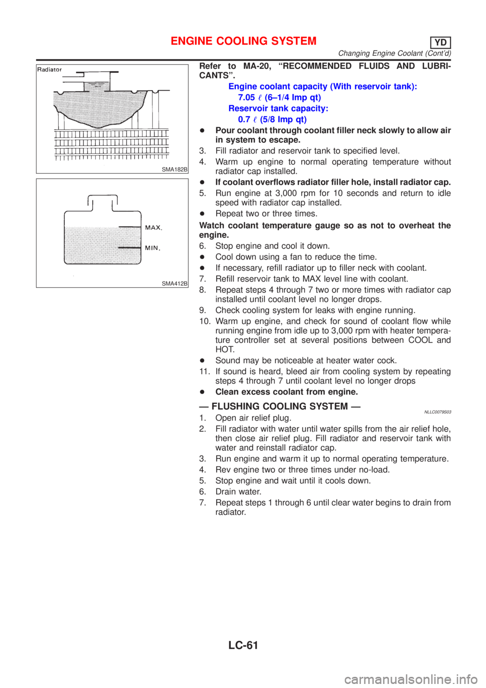
SMA182B
SMA412B
Refer to MA-20, ªRECOMMENDED FLUIDS AND LUBRI-
CANTSº.
Engine coolant capacity (With reservoir tank):
7.05!(6±1/4 Imp qt)
Reservoir tank capacity:
0.7!(5/8 Imp qt)
+Pour coolant through coolant filler neck slowly to allow air
in system to escape.
3. Fill radiator and reservoir tank to specified level.
4. Warm up engine to normal operating temperature without
radiator cap installed.
+If coolant overflows radiator filler hole, install radiator cap.
5. Run engine at 3,000 rpm for 10 seconds and return to idle
speed with radiator cap installed.
+Repeat two or three times.
Watch coolant temperature gauge so as not to overheat the
engine.
6. Stop engine and cool it down.
+Cool down using a fan to reduce the time.
+If necessary, refill radiator up to filler neck with coolant.
7. Refill reservoir tank to MAX level line with coolant.
8. Repeat steps 4 through 7 two or more times with radiator cap
installed until coolant level no longer drops.
9. Check cooling system for leaks with engine running.
10. Warm up engine, and check for sound of coolant flow while
running engine from idle up to 3,000 rpm with heater tempera-
ture controller set at several positions between COOL and
HOT.
+Sound may be noticeable at heater water cock.
11. If sound is heard, bleed air from cooling system by repeating
steps 4 through 7 until coolant level no longer drops
+Clean excess coolant from engine.
Ð FLUSHING COOLING SYSTEM ÐNLLC0079S031. Open air relief plug.
2. Fill radiator with water until water spills from the air relief hole,
then close air relief plug. Fill radiator and reservoir tank with
water and reinstall radiator cap.
3. Run engine and warm it up to normal operating temperature.
4. Rev engine two or three times under no-load.
5. Stop engine and wait until it cools down.
6. Drain water.
7. Repeat steps 1 through 6 until clear water begins to drain from
radiator.
ENGINE COOLING SYSTEMYD
Changing Engine Coolant (Cont'd)
LC-61
Page 2766 of 3051
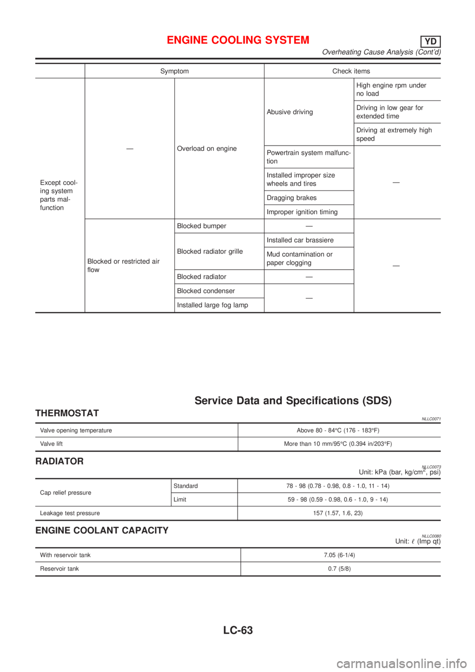
Symptom Check items
Except cool-
ing system
parts mal-
functionÐ Overload on engineAbusive drivingHigh engine rpm under
no load
Driving in low gear for
extended time
Driving at extremely high
speed
Powertrain system malfunc-
tion
Ð Installed improper size
wheels and tires
Dragging brakes
Improper ignition timing
Blocked or restricted air
flowBlocked bumper Ð
Ð Blocked radiator grilleInstalled car brassiere
Mud contamination or
paper clogging
Blocked radiator Ð
Blocked condenser
Ð
Installed large fog lamp
Service Data and Specifications (SDS)
THERMOSTATNLLC0071
Valve opening temperature Above 80 - 84ÉC (176 - 183ÉF)
Valve liftMore than 10 mm/95ÉC (0.394 in/203ÉF)
RADIATORNLLC0073Unit: kPa (bar, kg/cm2, psi)
Cap relief pressureStandard 78 - 98 (0.78 - 0.98, 0.8 - 1.0, 11 - 14)
Limit 59 - 98 (0.59 - 0.98, 0.6 - 1.0,9-14)
Leakage test pressure157 (1.57, 1.6, 23)
ENGINE COOLANT CAPACITYNLLC0080Unit:!(Imp qt)
With reservoir tank7.05 (6-1/4)
Reservoir tank0.7 (5/8)
ENGINE COOLING SYSTEMYD
Overheating Cause Analysis (Cont'd)
LC-63
Page 2995 of 3051

BatteryNLSC0014
Applied model QG engine YD22 engine
TypeYUASA type code YUASA type code
025 027 065 075 079 067 096
Capacity V-AH 12 - 52 12-55 12-50 12-42 12-60 12-64
StarterNLSC0015
Type0 001 116 006 D7E31 S114-800B S1114-871 M8T75371
BOSCH make VALEO make HITACHI make MITSUBISHI make
Non-reduction Non-reduction Reduction Reduction Reduction
Applied model QG engine SR engine YD22 engine
System voltage V12
No-loadTerminal voltage V 11.5 11.0 11.0 11.0 11.0
Current A Less than 48 45 Less than 90 Less than 90 Less than 145
Revolution rpm More than 5,800 12,000 More than 2,700 More than 2,300 More than 3,400
Minimum diameter of commutator mm
(in)33.5 (1.319) 28.2 (1,110) 28.0 (1.102) 31.4 (1.236)
Minimum length of brush mm (in) 3.5 (0.138) 6.15 (0.242) 10.5 (0.413) 11.0 (0.433)
Brush spring tension N (kg, lb)5.2 (0.53, 1.17) at
7.5 mm (0.295 in)
brush length16.2 - 19.8
(1.65 - 2.02,
3.46 - 4.45)12.7 - 17.7
(1.3 - 1.8,
2.9 - 4.0)26.5 - 36.3
(2.7 - 3.7,
6.0 - 8.2)
Clearance between bearing metal and
armature shaft mm (in)—0.05 (0.002) Less than 0.2 (0.008)—
Clearance“!”between pinion front edge
and pinion stopper mm (in)0.0 - 3.9
(0 - 0.154)Max. 1 (0.039) 0.3 - 2.5 (0.012 - 0.098)—
Movement“!”in height of pinion assem-
bly mm (in)—Max. 12.2 (0.480)—0.5 - 2.0
(0.020 - 0.079)
AlternatorNLSC0016
TypeLR180-762 LR190-747 LR1100-724 A2TB3891
HITACHI make MITSUBISHI make
Applied model QG engine SR engine YD engine SR engine
Nominal rating V-A 12-80 12-90 12-100 12-90
Ground polarityNegative
Minimum revolutions under no-load (When
13.5V is applied) rpmLess than 1,000 Less than 1,300
Hot output current (When 13.5V is applied)
A/rpmMore than 23/1,300
More than 65/2,500
More than 87/5,000More than 34/1,300
More than 83/2,500
More than 91/5,000More than 22/1,300
More than 64/2,500
More than 85/5,000
Regulated output voltage V 14.1 - 14.7
Minimum length of brush mm (in) 6.0 (0.236) 5.0 (0.197)
Brush spring pressure N (g, oz) 1.0 - 3.43 (102 - 350, 3.60 - 12.34)4.8 - 5.0
(490 - 610, 17.28 -
21.51)
Slip ring minimum diameter mm (in) 6.0 (1.024) 22.1 (0.870)
Rotor coil resistance at 20°C (68°F)Ω2.67 2.31 1.8 - 2.1
SERVICE DATA AND SPECIFICATIONS (SDS)
Battery
SC-34