2001 NISSAN ALMERA TINO power steering
[x] Cancel search: power steeringPage 431 of 3051
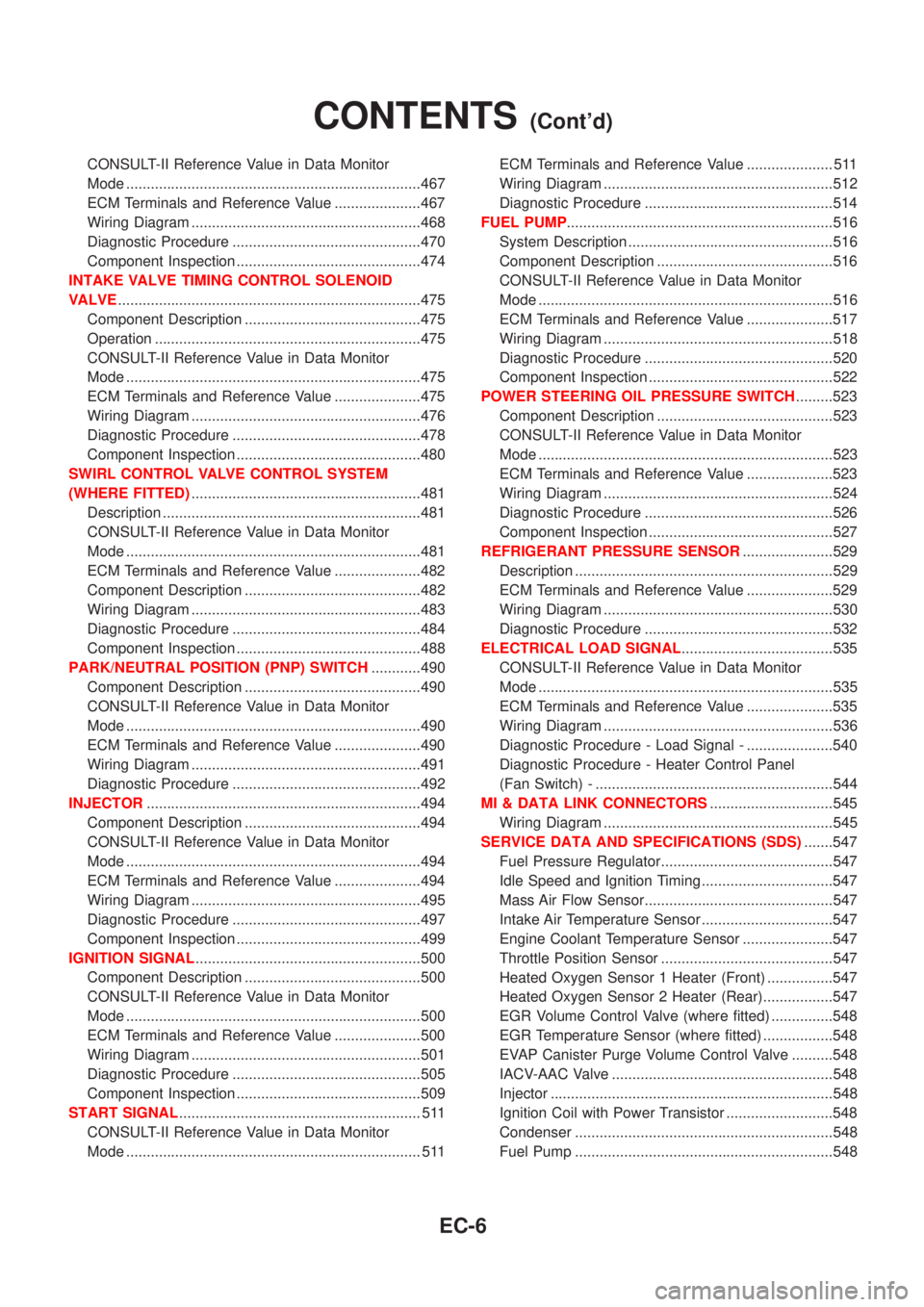
CONSULT-II Reference Value in Data Monitor
Mode ........................................................................467
ECM Terminals and Reference Value .....................467
Wiring Diagram ........................................................468
Diagnostic Procedure ..............................................470
Component Inspection .............................................474
INTAKE VALVE TIMING CONTROL SOLENOID
VALVE..........................................................................475
Component Description ...........................................475
Operation .................................................................475
CONSULT-II Reference Value in Data Monitor
Mode ........................................................................475
ECM Terminals and Reference Value .....................475
Wiring Diagram ........................................................476
Diagnostic Procedure ..............................................478
Component Inspection .............................................480
SWIRL CONTROL VALVE CONTROL SYSTEM
(WHERE FITTED)........................................................481
Description ...............................................................481
CONSULT-II Reference Value in Data Monitor
Mode ........................................................................481
ECM Terminals and Reference Value .....................482
Component Description ...........................................482
Wiring Diagram ........................................................483
Diagnostic Procedure ..............................................484
Component Inspection .............................................488
PARK/NEUTRAL POSITION (PNP) SWITCH............490
Component Description ...........................................490
CONSULT-II Reference Value in Data Monitor
Mode ........................................................................490
ECM Terminals and Reference Value .....................490
Wiring Diagram ........................................................491
Diagnostic Procedure ..............................................492
INJECTOR...................................................................494
Component Description ...........................................494
CONSULT-II Reference Value in Data Monitor
Mode ........................................................................494
ECM Terminals and Reference Value .....................494
Wiring Diagram ........................................................495
Diagnostic Procedure ..............................................497
Component Inspection .............................................499
IGNITION SIGNAL.......................................................500
Component Description ...........................................500
CONSULT-II Reference Value in Data Monitor
Mode ........................................................................500
ECM Terminals and Reference Value .....................500
Wiring Diagram ........................................................501
Diagnostic Procedure ..............................................505
Component Inspection .............................................509
START SIGNAL........................................................... 511
CONSULT-II Reference Value in Data Monitor
Mode ........................................................................ 511ECM Terminals and Reference Value ..................... 511
Wiring Diagram ........................................................512
Diagnostic Procedure ..............................................514
FUEL PUMP.................................................................516
System Description ..................................................516
Component Description ...........................................516
CONSULT-II Reference Value in Data Monitor
Mode ........................................................................516
ECM Terminals and Reference Value .....................517
Wiring Diagram ........................................................518
Diagnostic Procedure ..............................................520
Component Inspection .............................................522
POWER STEERING OIL PRESSURE SWITCH.........523
Component Description ...........................................523
CONSULT-II Reference Value in Data Monitor
Mode ........................................................................523
ECM Terminals and Reference Value .....................523
Wiring Diagram ........................................................524
Diagnostic Procedure ..............................................526
Component Inspection .............................................527
REFRIGERANT PRESSURE SENSOR......................529
Description ...............................................................529
ECM Terminals and Reference Value .....................529
Wiring Diagram ........................................................530
Diagnostic Procedure ..............................................532
ELECTRICAL LOAD SIGNAL.....................................535
CONSULT-II Reference Value in Data Monitor
Mode ........................................................................535
ECM Terminals and Reference Value .....................535
Wiring Diagram ........................................................536
Diagnostic Procedure - Load Signal - .....................540
Diagnostic Procedure - Heater Control Panel
(Fan Switch) - ..........................................................544
MI & DATA LINK CONNECTORS..............................545
Wiring Diagram ........................................................545
SERVICE DATA AND SPECIFICATIONS (SDS).......547
Fuel Pressure Regulator..........................................547
Idle Speed and Ignition Timing ................................547
Mass Air Flow Sensor..............................................547
Intake Air Temperature Sensor ................................547
Engine Coolant Temperature Sensor ......................547
Throttle Position Sensor ..........................................547
Heated Oxygen Sensor 1 Heater (Front) ................547
Heated Oxygen Sensor 2 Heater (Rear).................547
EGR Volume Control Valve (where fitted) ...............548
EGR Temperature Sensor (where fitted) .................548
EVAP Canister Purge Volume Control Valve ..........548
IACV-AAC Valve ......................................................548
Injector .....................................................................548
Ignition Coil with Power Transistor ..........................548
Condenser ...............................................................548
Fuel Pump ...............................................................548
CONTENTS(Cont'd)
EC-6
Page 437 of 3051
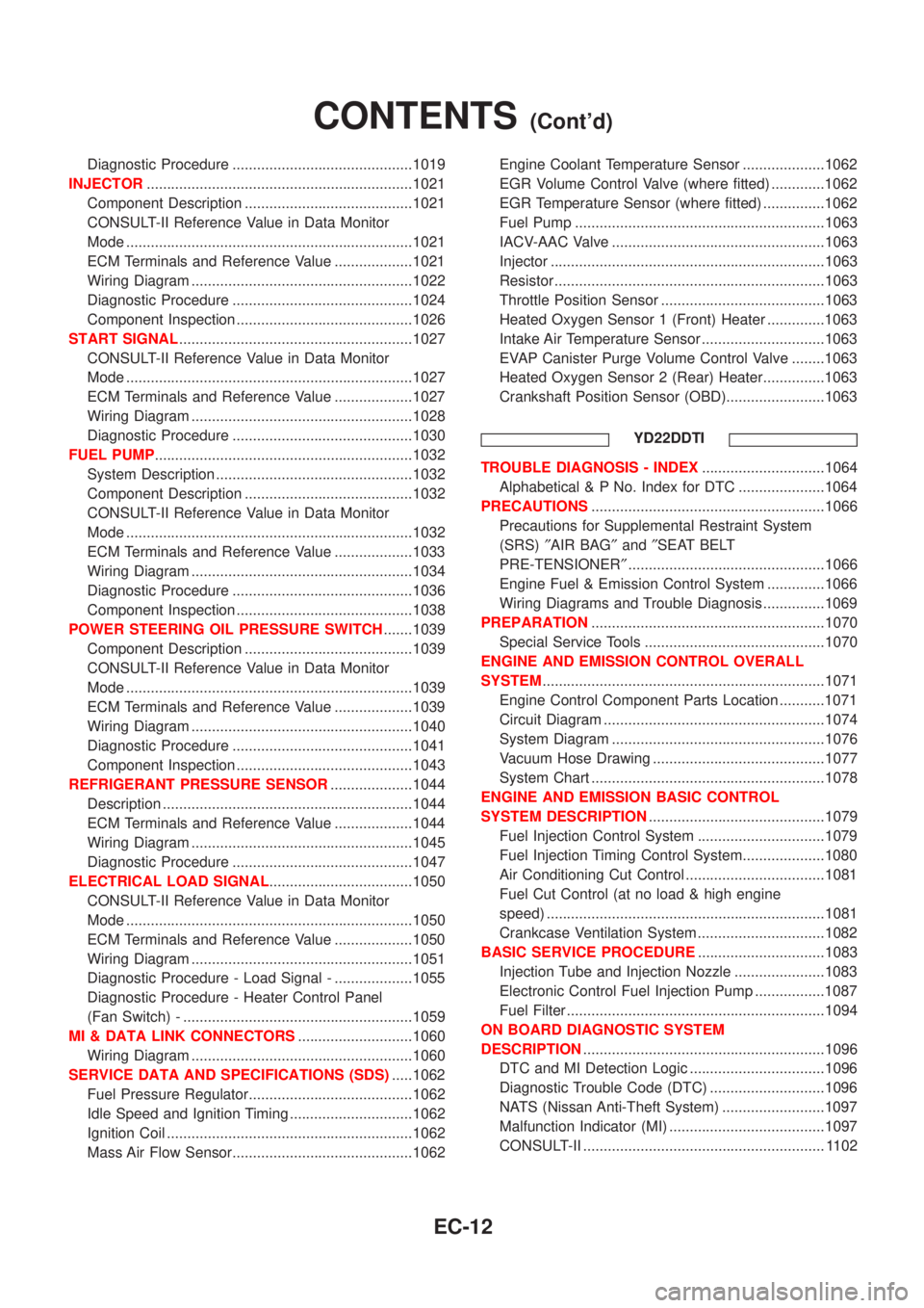
Diagnostic Procedure ............................................1019
INJECTOR.................................................................1021
Component Description .........................................1021
CONSULT-II Reference Value in Data Monitor
Mode ......................................................................1021
ECM Terminals and Reference Value ...................1021
Wiring Diagram ......................................................1022
Diagnostic Procedure ............................................1024
Component Inspection ...........................................1026
START SIGNAL.........................................................1027
CONSULT-II Reference Value in Data Monitor
Mode ......................................................................1027
ECM Terminals and Reference Value ...................1027
Wiring Diagram ......................................................1028
Diagnostic Procedure ............................................1030
FUEL PUMP...............................................................1032
System Description ................................................1032
Component Description .........................................1032
CONSULT-II Reference Value in Data Monitor
Mode ......................................................................1032
ECM Terminals and Reference Value ...................1033
Wiring Diagram ......................................................1034
Diagnostic Procedure ............................................1036
Component Inspection ...........................................1038
POWER STEERING OIL PRESSURE SWITCH.......1039
Component Description .........................................1039
CONSULT-II Reference Value in Data Monitor
Mode ......................................................................1039
ECM Terminals and Reference Value ...................1039
Wiring Diagram ......................................................1040
Diagnostic Procedure ............................................1041
Component Inspection ...........................................1043
REFRIGERANT PRESSURE SENSOR....................1044
Description .............................................................1044
ECM Terminals and Reference Value ...................1044
Wiring Diagram ......................................................1045
Diagnostic Procedure ............................................1047
ELECTRICAL LOAD SIGNAL...................................1050
CONSULT-II Reference Value in Data Monitor
Mode ......................................................................1050
ECM Terminals and Reference Value ...................1050
Wiring Diagram ......................................................1051
Diagnostic Procedure - Load Signal - ...................1055
Diagnostic Procedure - Heater Control Panel
(Fan Switch) - ........................................................1059
MI & DATA LINK CONNECTORS............................1060
Wiring Diagram ......................................................1060
SERVICE DATA AND SPECIFICATIONS (SDS).....1062
Fuel Pressure Regulator........................................1062
Idle Speed and Ignition Timing ..............................1062
Ignition Coil ............................................................1062
Mass Air Flow Sensor............................................1062Engine Coolant Temperature Sensor ....................1062
EGR Volume Control Valve (where fitted) .............1062
EGR Temperature Sensor (where fitted) ...............1062
Fuel Pump .............................................................1063
IACV-AAC Valve ....................................................1063
Injector ...................................................................1063
Resistor ..................................................................1063
Throttle Position Sensor ........................................1063
Heated Oxygen Sensor 1 (Front) Heater ..............1063
Intake Air Temperature Sensor ..............................1063
EVAP Canister Purge Volume Control Valve ........1063
Heated Oxygen Sensor 2 (Rear) Heater...............1063
Crankshaft Position Sensor (OBD)........................1063
YD22DDTI
TROUBLE DIAGNOSIS - INDEX..............................1064
Alphabetical & P No. Index for DTC .....................1064
PRECAUTIONS.........................................................1066
Precautions for Supplemental Restraint System
(SRS)²AIR BAG²and²SEAT BELT
PRE-TENSIONER²................................................1066
Engine Fuel & Emission Control System ..............1066
Wiring Diagrams and Trouble Diagnosis ...............1069
PREPARATION.........................................................1070
Special Service Tools ............................................1070
ENGINE AND EMISSION CONTROL OVERALL
SYSTEM.....................................................................1071
Engine Control Component Parts Location ...........1071
Circuit Diagram ......................................................1074
System Diagram ....................................................1076
Vacuum Hose Drawing ..........................................1077
System Chart .........................................................1078
ENGINE AND EMISSION BASIC CONTROL
SYSTEM DESCRIPTION...........................................1079
Fuel Injection Control System ...............................1079
Fuel Injection Timing Control System....................1080
Air Conditioning Cut Control ..................................1081
Fuel Cut Control (at no load & high engine
speed) ....................................................................1081
Crankcase Ventilation System ...............................1082
BASIC SERVICE PROCEDURE...............................1083
Injection Tube and Injection Nozzle ......................1083
Electronic Control Fuel Injection Pump .................1087
Fuel Filter ...............................................................1094
ON BOARD DIAGNOSTIC SYSTEM
DESCRIPTION...........................................................1096
DTC and MI Detection Logic .................................1096
Diagnostic Trouble Code (DTC) ............................1096
NATS (Nissan Anti-Theft System) .........................1097
Malfunction Indicator (MI) ......................................1097
CONSULT-II ........................................................... 1102
CONTENTS(Cont'd)
EC-12
Page 459 of 3051
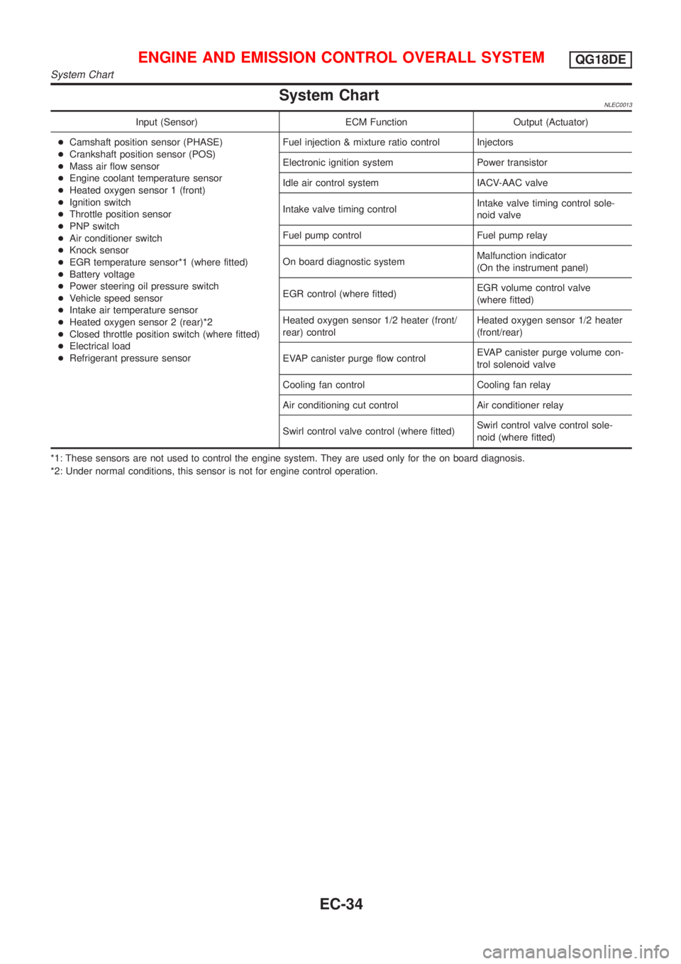
System ChartNLEC0013
Input (Sensor) ECM Function Output (Actuator)
+Camshaft position sensor (PHASE)
+Crankshaft position sensor (POS)
+Mass air flow sensor
+Engine coolant temperature sensor
+Heated oxygen sensor 1 (front)
+Ignition switch
+Throttle position sensor
+PNP switch
+Air conditioner switch
+Knock sensor
+EGR temperature sensor*1 (where fitted)
+Battery voltage
+Power steering oil pressure switch
+Vehicle speed sensor
+Intake air temperature sensor
+Heated oxygen sensor 2 (rear)*2
+Closed throttle position switch (where fitted)
+Electrical load
+Refrigerant pressure sensorFuel injection & mixture ratio control Injectors
Electronic ignition system Power transistor
Idle air control system IACV-AAC valve
Intake valve timing controlIntake valve timing control sole-
noid valve
Fuel pump control Fuel pump relay
On board diagnostic systemMalfunction indicator
(On the instrument panel)
EGR control (where fitted)EGR volume control valve
(where fitted)
Heated oxygen sensor 1/2 heater (front/
rear) controlHeated oxygen sensor 1/2 heater
(front/rear)
EVAP canister purge flow controlEVAP canister purge volume con-
trol solenoid valve
Cooling fan control Cooling fan relay
Air conditioning cut control Air conditioner relay
Swirl control valve control (where fitted)Swirl control valve control sole-
noid (where fitted)
*1: These sensors are not used to control the engine system. They are used only for the on board diagnosis.
*2: Under normal conditions, this sensor is not for engine control operation.
ENGINE AND EMISSION CONTROL OVERALL SYSTEMQG18DE
System Chart
EC-34
Page 460 of 3051
Multiport Fuel Injection (MFI) System
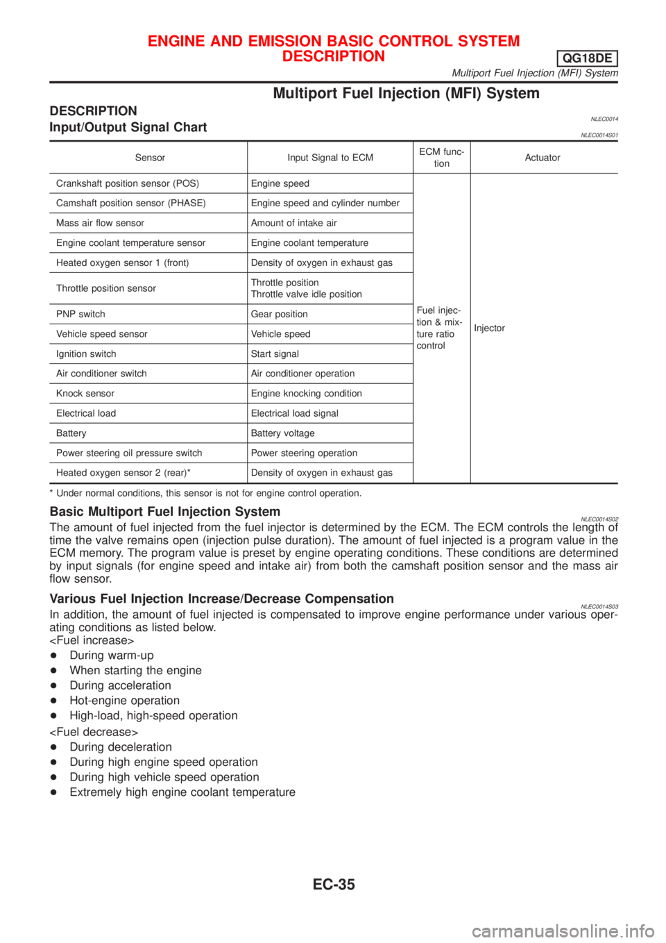
DESCRIPTIONNLEC0014Input/Output Signal ChartNLEC0014S01
Sensor Input Signal to ECMECM func-
tionActuator
Crankshaft position sensor (POS) Engine speed
Fuel injec-
tion & mix-
ture ratio
controlInjector Camshaft position sensor (PHASE) Engine speed and cylinder number
Mass air flow sensor Amount of intake air
Engine coolant temperature sensor Engine coolant temperature
Heated oxygen sensor 1 (front) Density of oxygen in exhaust gas
Throttle position sensorThrottle position
Throttle valve idle position
PNP switch Gear position
Vehicle speed sensor Vehicle speed
Ignition switch Start signal
Air conditioner switch Air conditioner operation
Knock sensor Engine knocking condition
Electrical load Electrical load signal
Battery Battery voltage
Power steering oil pressure switch Power steering operation
Heated oxygen sensor 2 (rear)* Density of oxygen in exhaust gas
* Under normal conditions, this sensor is not for engine control operation.
Basic Multiport Fuel Injection SystemNLEC0014S02The amount of fuel injected from the fuel injector is determined by the ECM. The ECM controls the length of
time the valve remains open (injection pulse duration). The amount of fuel injected is a program value in the
ECM memory. The program value is preset by engine operating conditions. These conditions are determined
by input signals (for engine speed and intake air) from both the camshaft position sensor and the mass air
flow sensor.
Various Fuel Injection Increase/Decrease CompensationNLEC0014S03In addition, the amount of fuel injected is compensated to improve engine performance under various oper-
ating conditions as listed below.
+During warm-up
+When starting the engine
+During acceleration
+Hot-engine operation
+High-load, high-speed operation
+During deceleration
+During high engine speed operation
+During high vehicle speed operation
+Extremely high engine coolant temperature
ENGINE AND EMISSION BASIC CONTROL SYSTEM
DESCRIPTION
QG18DE
Multiport Fuel Injection (MFI) System
EC-35
Page 463 of 3051
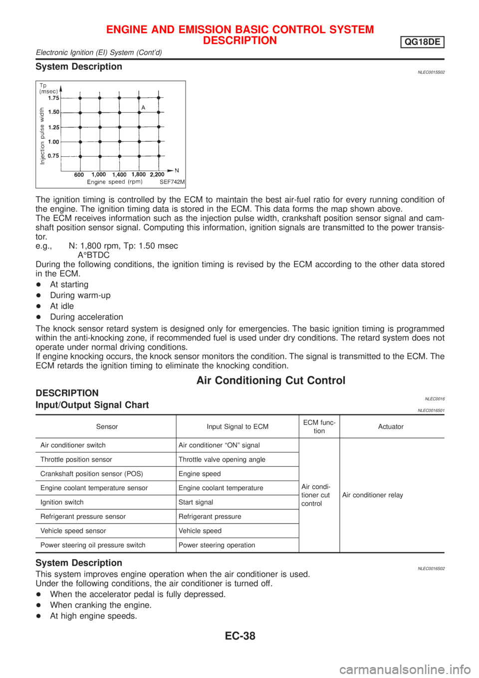
System DescriptionNLEC0015S02
SEF742M
The ignition timing is controlled by the ECM to maintain the best air-fuel ratio for every running condition of
the engine. The ignition timing data is stored in the ECM. This data forms the map shown above.
The ECM receives information such as the injection pulse width, crankshaft position sensor signal and cam-
shaft position sensor signal. Computing this information, ignition signals are transmitted to the power transis-
tor.
e.g., N: 1,800 rpm, Tp: 1.50 msec
AÉBTDC
During the following conditions, the ignition timing is revised by the ECM according to the other data stored
in the ECM.
+At starting
+During warm-up
+At idle
+During acceleration
The knock sensor retard system is designed only for emergencies. The basic ignition timing is programmed
within the anti-knocking zone, if recommended fuel is used under dry conditions. The retard system does not
operate under normal driving conditions.
If engine knocking occurs, the knock sensor monitors the condition. The signal is transmitted to the ECM. The
ECM retards the ignition timing to eliminate the knocking condition.
Air Conditioning Cut Control
DESCRIPTIONNLEC0016Input/Output Signal ChartNLEC0016S01
Sensor Input Signal to ECMECM func-
tionActuator
Air conditioner switch Air conditioner ªONº signal
Air condi-
tioner cut
controlAir conditioner relay Throttle position sensor Throttle valve opening angle
Crankshaft position sensor (POS) Engine speed
Engine coolant temperature sensor Engine coolant temperature
Ignition switch Start signal
Refrigerant pressure sensor Refrigerant pressure
Vehicle speed sensor Vehicle speed
Power steering oil pressure switch Power steering operation
System DescriptionNLEC0016S02This system improves engine operation when the air conditioner is used.
Under the following conditions, the air conditioner is turned off.
+When the accelerator pedal is fully depressed.
+When cranking the engine.
+At high engine speeds.
ENGINE AND EMISSION BASIC CONTROL SYSTEM
DESCRIPTION
QG18DE
Electronic Ignition (EI) System (Cont'd)
EC-38
Page 464 of 3051
+When the engine coolant temperature becomes excessively high.
+When operating power steering during low engine speed or low vehicle speed.
+When engine speed is excessively low.
+When the refrigerant pressure is excessively high or low.
Fuel Cut Control (at no load & high engine
speed)
DESCRIPTIONNLEC0017Input/Output Signal ChartNLEC0017S01
Sensor Input Signal to ECMECM func-
tionActuator
Vehicle speed sensor Vehicle speed
Fuel cut
controlInjectors PNP switch Neutral position
Throttle position sensor Throttle position
Engine coolant temperature sensor Engine coolant temperature
Crankshaft position sensor (POS) Engine speed
Camshaft position sensor (PHASE) Engine speed and cylinder number
If the engine speed is above 3,950 rpm with no load, (for example, in Neutral and engine speed over 4,000
rpm) fuel will be cut off after some time. The exact time when the fuel is cut off varies based on engine speed.
Fuel cut will operate until the engine speed reaches 1,150 rpm, then fuel cut is cancelled.
NOTE:
This function is different from deceleration control listed under ªMultiport Fuel Injection (MFI) Systemº,
EC-35.
Evaporative Emission System
DESCRIPTIONNLEC0018
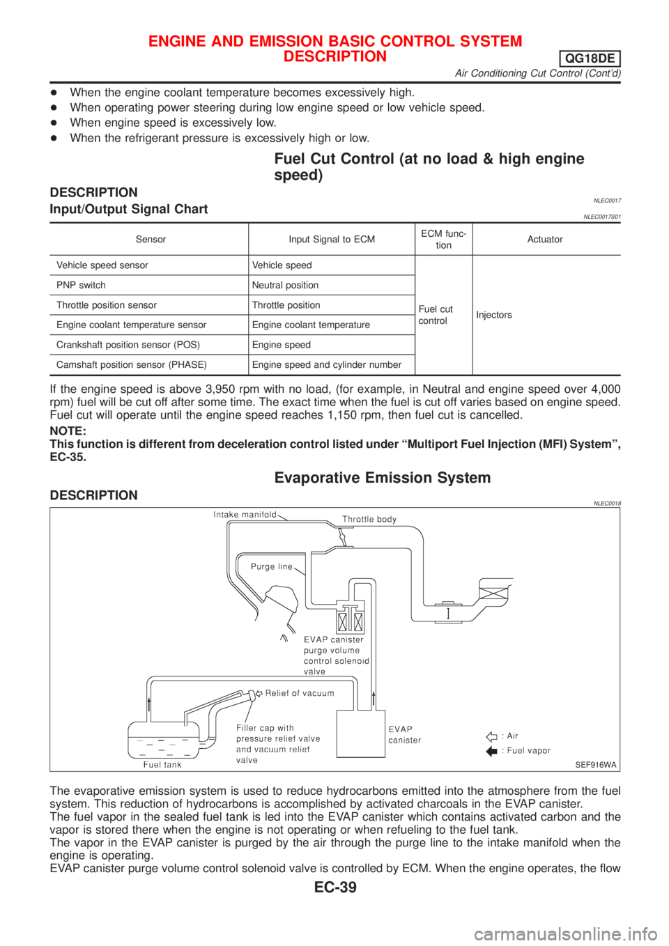
SEF916WA
The evaporative emission system is used to reduce hydrocarbons emitted into the atmosphere from the fuel
system. This reduction of hydrocarbons is accomplished by activated charcoals in the EVAP canister.
The fuel vapor in the sealed fuel tank is led into the EVAP canister which contains activated carbon and the
vapor is stored there when the engine is not operating or when refueling to the fuel tank.
The vapor in the EVAP canister is purged by the air through the purge line to the intake manifold when the
engine is operating.
EVAP canister purge volume control solenoid valve is controlled by ECM. When the engine operates, the flow
ENGINE AND EMISSION BASIC CONTROL SYSTEM
DESCRIPTION
QG18DE
Air Conditioning Cut Control (Cont'd)
EC-39
Page 508 of 3051
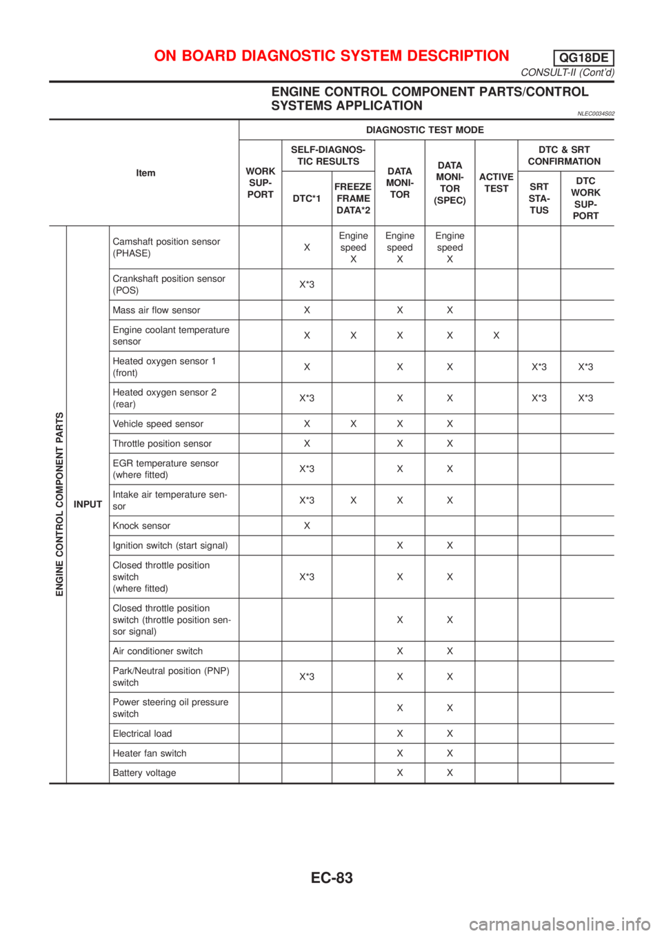
ENGINE CONTROL COMPONENT PARTS/CONTROL
SYSTEMS APPLICATION
NLEC0034S02
ItemDIAGNOSTIC TEST MODE
WORK
SUP-
PORTSELF-DIAGNOS-
TIC RESULTS
D ATA
MONI-
TORD ATA
MONI-
TOR
(SPEC)ACTIVE
TESTDTC & SRT
CONFIRMATION
DTC*1FREEZE
FRAME
DATA*2SRT
STA-
TUSDTC
WORK
SUP-
PORT
ENGINE CONTROL COMPONENT PARTS
INPUTCamshaft position sensor
(PHASE)XEngine
speed
XEngine
speed
XEngine
speed
X
Crankshaft position sensor
(POS)X*3
Mass air flow sensor X X X
Engine coolant temperature
sensorXXX XX
Heated oxygen sensor 1
(front)X X X X*3 X*3
Heated oxygen sensor 2
(rear)X*3 X X X*3 X*3
Vehicle speed sensor X X X X
Throttle position sensor X X X
EGR temperature sensor
(where fitted)X*3 X X
Intake air temperature sen-
sorX*3 X X X
Knock sensor X
Ignition switch (start signal) X X
Closed throttle position
switch
(where fitted)X*3 X X
Closed throttle position
switch (throttle position sen-
sor signal)XX
Air conditioner switch X X
Park/Neutral position (PNP)
switchX*3 X X
Power steering oil pressure
switchXX
Electrical load X X
Heater fan switch X X
Battery voltage X X
ON BOARD DIAGNOSTIC SYSTEM DESCRIPTIONQG18DE
CONSULT-II (Cont'd)
EC-83
Page 512 of 3051
![NISSAN ALMERA TINO 2001 Service Repair Manual Monitored item [Unit]ECM
input
signalsMain
signalsDescription Remarks
HO2S2 MNTR (B1)
[RICH/LEAN]j+Display of heated oxygen sensor 2 (rear) sig-
nal:
RICH ... means the amount of oxygen after
three wa NISSAN ALMERA TINO 2001 Service Repair Manual Monitored item [Unit]ECM
input
signalsMain
signalsDescription Remarks
HO2S2 MNTR (B1)
[RICH/LEAN]j+Display of heated oxygen sensor 2 (rear) sig-
nal:
RICH ... means the amount of oxygen after
three wa](/manual-img/5/57352/w960_57352-511.png)
Monitored item [Unit]ECM
input
signalsMain
signalsDescription Remarks
HO2S2 MNTR (B1)
[RICH/LEAN]j+Display of heated oxygen sensor 2 (rear) sig-
nal:
RICH ... means the amount of oxygen after
three way catalyst is relatively small.
LEAN ... means the amount of oxygen after
three way catalyst is relatively large.+When the engine is stopped, a cer-
tain value is indicated.
VHCL SPEED SE
[km/h] or [mph]jj+The vehicle speed computed from the vehicle
speed sensor signal is displayed.
BATTERY VOLT [V]j+The power supply voltage of ECM is dis-
played.
THRTL POS SEN [V]jj+The throttle position sensor signal voltage is
displayed.
INT/A TEMP SE
[ÉC] or [ÉF]j+The intake air temperature determined by the
signal voltage of the intake air temperature
sensor is indicated.
EGR TEMP SEN [V]
(where fitted)jj+The signal voltage of the EGR temperature
sensor is displayed.
START SIGNAL
[ON/OFF]jj+Indicates [ON/OFF] condition from the starter
signal.+After starting the engine, [OFF] is
displayed regardless of the starter
signal.
CLSD THL POS
[ON/OFF]jj+Indicates idle position [ON/OFF] computed by
ECM according to the throttle position sensor
signal.
CLSD THL/P SW
[ON/OFF]
(where fitted)j+Indicates mechanical contact [ON/OFF] con-
dition of the closed throttle position switch.
AIR COND SIG
[ON/OFF]jj+Indicates [ON/OFF] condition of the air condi-
tioner switch as determined by the air condi-
tioning signal.
P/N POSI SW
[ON/OFF]jj+Indicates [ON/OFF] condition from the PNP
switch signal.
PW/ST SIGNAL
[ON/OFF]jj+Indicates [ON/OFF] condition of the power
steering oil pressure switch determined by
the power steering oil pressure switch signal.
LOAD SIGNAL
[ON/OFF]jj+Indicates [ON/OFF] condition from the electri-
cal load signal and/or lighting switch.
ON ... rear defogger is operating and/or light-
ing switch is on.
OFF ... rear defogger is not operating and
lighting switch is not on.
IGNITION SW
[ON/OFF]j+Indicates [ON/OFF] condition from ignition
switch.
HEATER FAN SW
[ON/OFF]j+Indicates [ON/OFF] condition from the heater
fan switch.
INJ PULSE-B1
[msec]j+Indicates the actual fuel injection pulse width
compensated by ECM according to the input
signals.+When the engine is stopped, a cer-
tain computed value is indicated.
IGN TIMING [BTDC]j+Indicates the ignition timing computed by
ECM according to the input signals.
ON BOARD DIAGNOSTIC SYSTEM DESCRIPTIONQG18DE
CONSULT-II (Cont'd)
EC-87