Page 534 of 3051

17 ADJUSTMENT THROTTLE POSITION SWITCH CLOSED POSITION-II
Without CONSULT-II
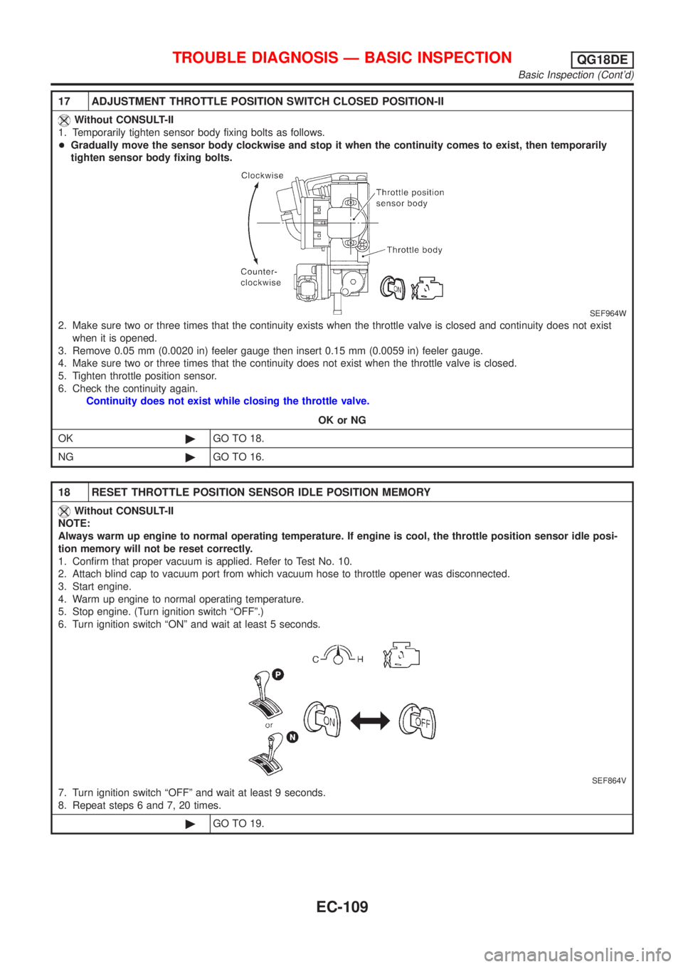
1. Temporarily tighten sensor body fixing bolts as follows.
+Gradually move the sensor body clockwise and stop it when the continuity comes to exist, then temporarily
tighten sensor body fixing bolts.
SEF964W
2. Make sure two or three times that the continuity exists when the throttle valve is closed and continuity does not exist
when it is opened.
3. Remove 0.05 mm (0.0020 in) feeler gauge then insert 0.15 mm (0.0059 in) feeler gauge.
4. Make sure two or three times that the continuity does not exist when the throttle valve is closed.
5. Tighten throttle position sensor.
6. Check the continuity again.
Continuity does not exist while closing the throttle valve.
OK or NG
OK©GO TO 18.
NG©GO TO 16.
18 RESET THROTTLE POSITION SENSOR IDLE POSITION MEMORY
Without CONSULT-II
NOTE:
Always warm up engine to normal operating temperature. If engine is cool, the throttle position sensor idle posi-
tion memory will not be reset correctly.
1. Confirm that proper vacuum is applied. Refer to Test No. 10.
2. Attach blind cap to vacuum port from which vacuum hose to throttle opener was disconnected.
3. Start engine.
4. Warm up engine to normal operating temperature.
5. Stop engine. (Turn ignition switch ªOFFº.)
6. Turn ignition switch ªONº and wait at least 5 seconds.
SEF864V
7. Turn ignition switch ªOFFº and wait at least 9 seconds.
8. Repeat steps 6 and 7, 20 times.
©GO TO 19.
TROUBLE DIAGNOSIS Ð BASIC INSPECTIONQG18DE
Basic Inspection (Cont'd)
EC-109
Page 1058 of 3051

15 ADJUSTMENT THROTTLE POSITION SWITCH CLOSED POSITION-II
Without CONSULT-II
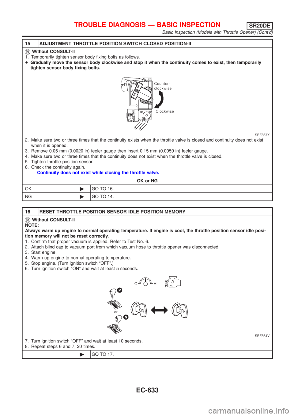
1. Temporarily tighten sensor body fixing bolts as follows.
+Gradually move the sensor body clockwise and stop it when the continuity comes to exist, then temporarily
tighten sensor body fixing bolts.
SEF867X
2. Make sure two or three times that the continuity exists when the throttle valve is closed and continuity does not exist
when it is opened.
3. Remove 0.05 mm (0.0020 in) feeler gauge then insert 0.15 mm (0.0059 in) feeler gauge.
4. Make sure two or three times that the continuity does not exist when the throttle valve is closed.
5. Tighten throttle position sensor.
6. Check the continuity again.
Continuity does not exist while closing the throttle valve.
OK or NG
OK©GO TO 16.
NG©GO TO 14.
16 RESET THROTTLE POSITION SENSOR IDLE POSITION MEMORY
Without CONSULT-II
NOTE:
Always warm up engine to normal operating temperature. If engine is cool, the throttle position sensor idle posi-
tion memory will not be reset correctly.
1. Confirm that proper vacuum is applied. Refer to Test No. 6.
2. Attach blind cap to vacuum port from which vacuum hose to throttle opener was disconnected.
3. Start engine.
4. Warm up engine to normal operating temperature.
5. Stop engine. (Turn ignition switch ªOFFº.)
6. Turn ignition switch ªONº and wait at least 5 seconds.
SEF864V
7. Turn ignition switch ªOFFº and wait at least 10 seconds.
8. Repeat steps 6 and 7, 20 times.
©GO TO 17.
TROUBLE DIAGNOSIS Ð BASIC INSPECTIONSR20DE
Basic Inspection (Models with Throttle Opener) (Cont'd)
EC-633
Page 1066 of 3051

9 ADJUST THROTTLE POSITION SENSOR IDLE POSITION
Without CONSULT-II
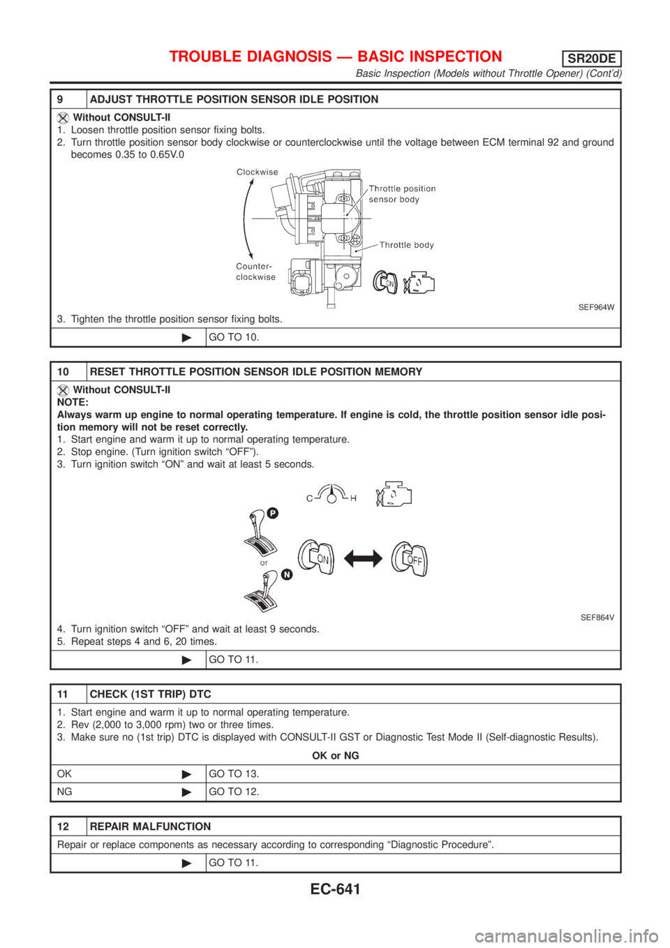
1. Loosen throttle position sensor fixing bolts.
2. Turn throttle position sensor body clockwise or counterclockwise until the voltage between ECM terminal 92 and ground
becomes 0.35 to 0.65V.0
SEF964W
3. Tighten the throttle position sensor fixing bolts.
©GO TO 10.
10 RESET THROTTLE POSITION SENSOR IDLE POSITION MEMORY
Without CONSULT-II
NOTE:
Always warm up engine to normal operating temperature. If engine is cold, the throttle position sensor idle posi-
tion memory will not be reset correctly.
1. Start engine and warm it up to normal operating temperature.
2. Stop engine. (Turn ignition switch ªOFFº).
3. Turn ignition switch ªONº and wait at least 5 seconds.
SEF864V
4. Turn ignition switch ªOFFº and wait at least 9 seconds.
5. Repeat steps 4 and 6, 20 times.
©GO TO 11.
11 CHECK (1ST TRIP) DTC
1. Start engine and warm it up to normal operating temperature.
2. Rev (2,000 to 3,000 rpm) two or three times.
3. Make sure no (1st trip) DTC is displayed with CONSULT-II GST or Diagnostic Test Mode II (Self-diagnostic Results).
OK or NG
OK©GO TO 13.
NG©GO TO 12.
12 REPAIR MALFUNCTION
Repair or replace components as necessary according to corresponding ªDiagnostic Procedureº.
©GO TO 11.
TROUBLE DIAGNOSIS Ð BASIC INSPECTIONSR20DE
Basic Inspection (Models without Throttle Opener) (Cont'd)
EC-641
Page 2598 of 3051

RHA273D
SERVICE COUPLERSNLHA0117S06Never attempt to connect HFC-134a (R-134a) service couplers to
an CFC-12 (R-12) A/C system. The HFC-134a (R-134a) couplers
will not properly connect to the CFC-12 (R-12) system. However, if
an improper connection is attempted, discharging and contamina-
tion may occur.
Shut-off valve rotation A/C service valve
Clockwise Open
Counterclockwise Close
RHA274D
REFRIGERANT WEIGHT SCALENLHA0117S07Verify that no refrigerant other than HFC-134a (R-134a) and speci-
fied lubricants have been used with the scale. If the scale controls
refrigerant flow electronically, the hose fitting must be 1/2″-16
ACME.
CALIBRATING ACR4 WEIGHT SCALENLHA0117S09Calibrate the scale every three months.
To calibrate the weight scale on the ACR4:
1. PressShift/ResetandEnterat the same time.
2. Press8787.“A1”will be displayed.
3. Remove all weight from the scale.
4. Press0, then pressEnter.“0.00”will be displayed and change
to“A2”.
5. Place a known weight (dumbbell or similar weight), between
4.5 and 36.3 kg (10 and 80 lb) on the center of the weight
scale.
6. Enter the known weight using four digits. (Example 10 lb =
“10.00”, 10.5 lb =“10.50”)
7. PressEnter—the display returns to the vacuum mode.
8. PressShift/ResetandEnterat the same time.
9. Press6—the known weight on the scale is displayed.
10. Remove the known weight from the scale.“0.00”will be dis-
played.
11. PressShift/Resetto return the ACR4 to the program mode.
CHARGING CYLINDERNLHA0117S08Using a charging cylinder is not recommended. Refrigerant may be
vented into air from cylinder’s top valve when filling the cylinder
with refrigerant. Also, the accuracy of the cylinder is generally less
than that of an electronic scale or of quality recycle/recharge
equipment.
PRECAUTIONS
Precautions for Service Equipment (Cont’d)
HA-7