2001 NISSAN ALMERA TINO tires
[x] Cancel search: tiresPage 213 of 3051

SBR686C
Precautions
PRECAUTIONSNLAX0001+When installing rubber parts, final tightening must be car-
ried out under unladen condition* with tires on ground.
*: Fuel, radiator coolant and engine oil full. Spare tire, jack,
hand tools and mats in designated positions.
+After installing removed suspension parts, check wheel
alignment and adjust if necessary.
+Use flare nut wrench when removing or installing brake
tubes.
+Always torque brake lines when installing.
Preparation
SPECIAL SERVICE TOOLSNLAX0002
Tool number
Tool nameDescription
HT72520000
Ball joint remover
NT146
Removing tie-rod outer end and lower ball joint
KV38106800
Differential side oil seal
protector
NT147
Installing drive shaft
KV38106800
COMMERCIAL SERVICE TOOLSNLAX0003
Tool name Description
1 Flare nut crowfoot
2 Torque wrench
NT360
Removing and installing each brake piping
a: 10 mm (0.39 in)
FRONT AXLE
Precautions
AX-2
Page 214 of 3051
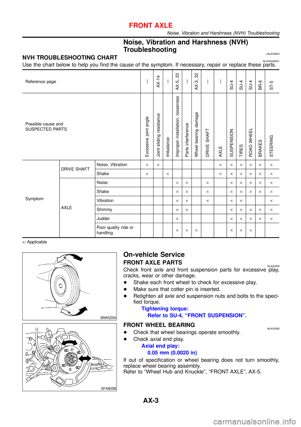
Noise, Vibration and Harshness (NVH)
Troubleshooting
=NLAX0004NVH TROUBLESHOOTING CHARTNLAX0004S01Use the chart below to help you find the cause of the symptom. If necessary, repair or replace these parts.
Reference page—
AX-14
—
AX-5, 23
—
AX-3, 22
—
—
SU-4
SU-4
SU-4
BR-6
ST-5
Possible cause and
SUSPECTED PARTS
Excessive joint angle
Joint sliding resistance
Imbalance
Improper installation, looseness
Parts interference
Wheel bearing damage
DRIVE SHAFT
AXLE
SUSPENSION
TIRES
ROAD WHEEL
BRAKES
STEERING
SymptomDRIVE SHAFTNoise, Vibration× × × ×××× ×
Shake× × × ×××× ×
AXLENoise×× × ×××× ×
Shake×× × ×××× ×
Vibration×× × ×× ×
Shimmy×× ×××× ×
Judder× ×××× ×
Poor quality ride or
handling××× ×××
×: Applicable
SMA525A
On-vehicle Service
FRONT AXLE PARTSNLAX0005Check front axle and front suspension parts for excessive play,
cracks, wear or other damage.
+Shake each front wheel to check for excessive play.
+Make sure that cotter pin is inserted.
+Retighten all axle and suspension nuts and bolts to the speci-
fied torque.
Tightening torque:
Refer to SU-4, “FRONT SUSPENSION”.
SFA805B
FRONT WHEEL BEARINGNLAX0006+Check that wheel bearings operate smoothly.
+Check axial end play.
Axial end play:
0.05 mm (0.0020 in)
If out of specification or wheel bearing does not turn smoothly,
replace wheel bearing assembly.
Refer to “Wheel Hub and Knuckle”, “FRONT AXLE”, AX-5.
FRONT AXLE
Noise, Vibration and Harshness (NVH) Troubleshooting
AX-3
Page 232 of 3051

SBR686C
Precautions
PRECAUTIONSNLAX0022+When installing each rubber part, final tightening must be
carried out under unladen condition* with tires on ground.
*: Fuel, radiator coolant and engine oil full. Spare tire, jack,
hand tools and mats in designated positions.
+Use flare nut wrench when removing or installing brake
tubes.
+After installing removed suspension parts, check wheel
alignment.
+Do not jack up at the trailing arm and lateral link.
+Always torque brake lines when installing.
Preparation
SPECIAL SERVICE TOOLSNLAX0032
Tool number
Tool nameDescription
KV40104710
Drift
NT474
Install ABS sensor rotor
a: 76.3 mm (3.004 in) dia.
b: 67.9 mm (2.673 in) dia.
ST3072000
Drift
NT115
Install ABS sensor rotor
a: 77 mm (3.03 in) dia.
b: 55.5 mm (2.185 in) dia.
COMMERCIAL SERVICE TOOLSNLAX0024
Tool name Description
1 Flare nut crowfoot
2 Torque wrench
NT360
Removing and installing brake piping
a: 10 mm (0.39 in)
REAR AXLE
Precautions
AX-21
Page 243 of 3051
NLBR0005
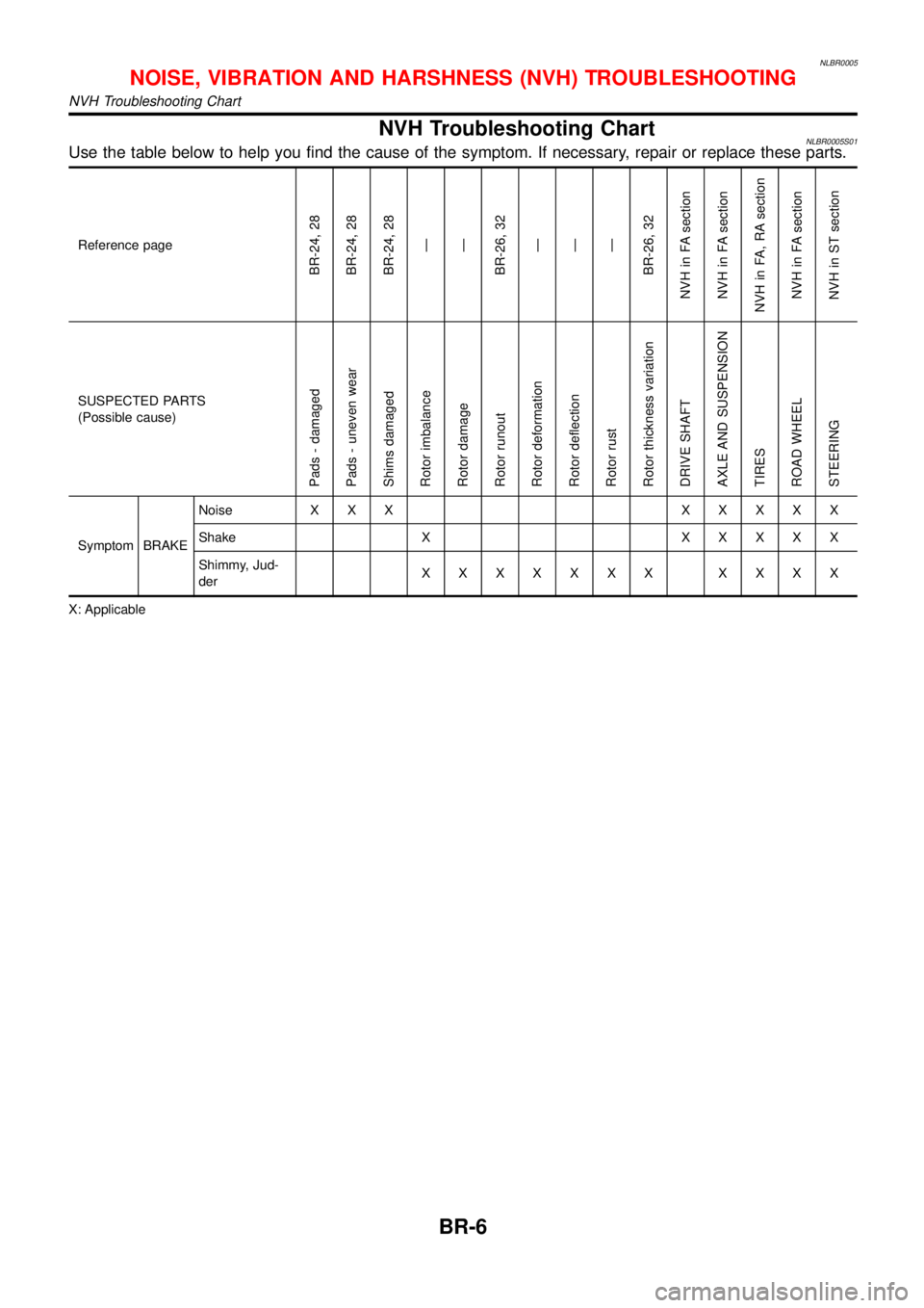
NVH Troubleshooting ChartNLBR0005S01Use the table below to help you find the cause of the symptom. If necessary, repair or replace these parts.
Reference page
BR-24, 28
BR-24, 28
BR-24, 28
—
—
BR-26, 32
—
—
—
BR-26, 32
NVH in FA section
NVH in FA section
NVH in FA, RA section
NVH in FA section
NVH in ST section
SUSPECTED PARTS
(Possible cause)
Pads - damaged
Pads - uneven wear
Shims damaged
Rotor imbalance
Rotor damage
Rotor runout
Rotor deformation
Rotor deflection
Rotor rust
Rotor thickness variation
DRIVE SHAFT
AXLE AND SUSPENSION
TIRES
ROAD WHEEL
STEERING
Symptom BRAKENoise X X XXXXXX
Shake XXXXXX
Shimmy, Jud-
derXXXXXXX XXXX
X: Applicable
NOISE, VIBRATION AND HARSHNESS (NVH) TROUBLESHOOTING
NVH Troubleshooting Chart
BR-6
Page 1803 of 3051
Aiming AdjustmentNLEL0016For details, refer to the regulations in your own country.
Before performing aiming adjustment, check the following.
1) Keep all tires inflated to correct pressures.
2) Place vehicle on flat surface.
3) See that there is no-load in vehicle (coolant, engine oil filled up
to correct level and full fuel tank) other than the driver (or
equivalent weight placed in driver's position).
SEL984W
CAUTION:
Be sure aiming switch is set to ª0º when performing aiming
adjustment on vehicles equipped with headlamp aiming con-
trol.
NEL734
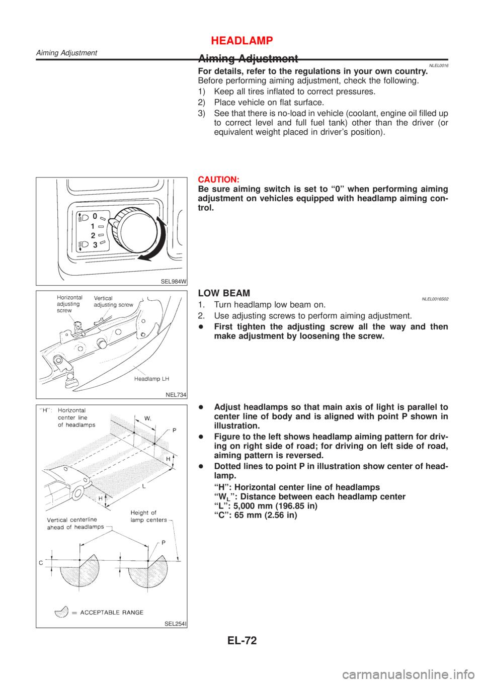
LOW BEAMNLEL0016S021. Turn headlamp low beam on.
2. Use adjusting screws to perform aiming adjustment.
+First tighten the adjusting screw all the way and then
make adjustment by loosening the screw.
SEL254I
+Adjust headlamps so that main axis of light is parallel to
center line of body and is aligned with point P shown in
illustration.
+Figure to the left shows headlamp aiming pattern for driv-
ing on right side of road; for driving on left side of road,
aiming pattern is reversed.
+Dotted lines to point P in illustration show center of head-
lamp.
ªHº: Horizontal center line of headlamps
ªW
Lº: Distance between each headlamp center
ªLº: 5,000 mm (196.85 in)
ªCº: 65 mm (2.56 in)
HEADLAMP
Aiming Adjustment
EL-72
Page 1829 of 3051
NEL714
Aiming Adjustment=NLEL0029Before performing aiming adjustment, make sure of the following.
1) Keep all tires inflated to correct pressure.
2) Place vehicle on level ground.
3) See that vehicle is unloaded (except for full levels of coolant,
engine oil and fuel, and spare tire, jack, and tools). Have the
driver or equivalent weight placed in driver's seat.
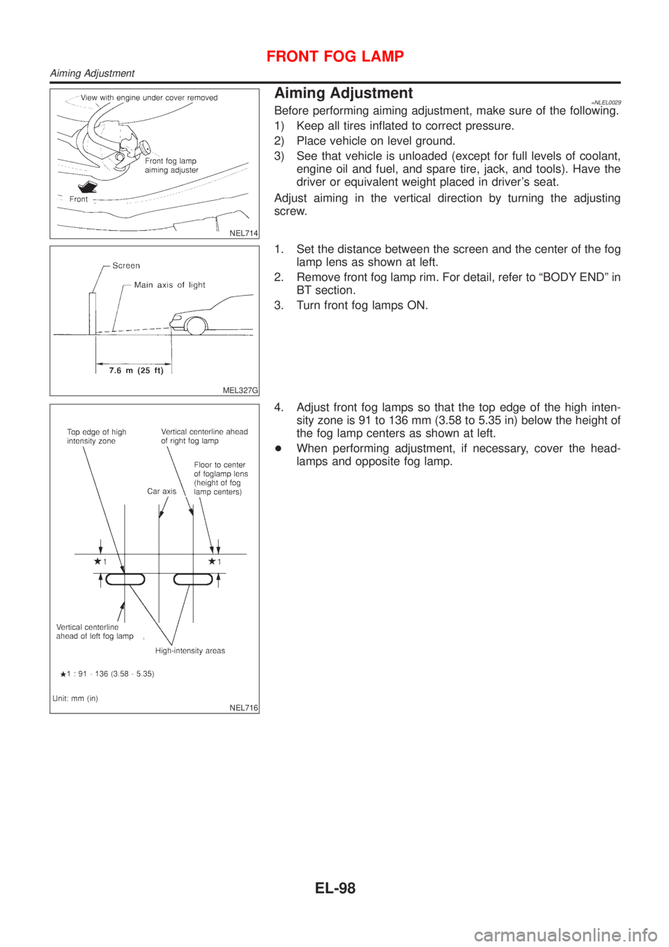
Adjust aiming in the vertical direction by turning the adjusting
screw.
MEL327G
1. Set the distance between the screen and the center of the fog
lamp lens as shown at left.
2. Remove front fog lamp rim. For detail, refer to ªBODY ENDº in
BT section.
3. Turn front fog lamps ON.
NEL716
4. Adjust front fog lamps so that the top edge of the high inten-
sity zone is 91 to 136 mm (3.58 to 5.35 in) below the height of
the fog lamp centers as shown at left.
+When performing adjustment, if necessary, cover the head-
lamps and opposite fog lamp.
FRONT FOG LAMP
Aiming Adjustment
EL-98
Page 2308 of 3051
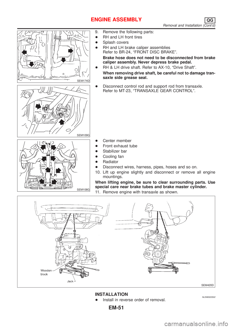
SEM174D
9. Remove the following parts:
+RH and LH front tires
+Splash covers
+RH and LH brake caliper assemblies
Refer to BR-24, ªFRONT DISC BRAKEº.
Brake hose does not need to be disconnected from brake
caliper assembly. Never depress brake pedal.
+RH & LH drive shaft. Refer to AX-10, ªDrive Shaftº.
When removing drive shaft, be careful not to damage tran-
saxle side grease seal.
SEM109G
+Disconnect control rod and support rod from transaxle.
Refer to MT-23, ªTRANSAXLE GEAR CONTROLº.
SEM108G
+Center member
+Front exhaust tube
+Stabilizer bar
+Cooling fan
+Radiator
+Disconnect wires, harness, pipes, hoses and so on.
10. Lift up engine slightly and disconnect or remove all engine
mountings.
When lifting engine, be sure to clear surrounding parts. Use
special care near brake tubes and brake master cylinder.
11. Remove engine with transaxle as shown.
SEM420D
INSTALLATIONNLEM0022S02+Install in reverse order of removal.
ENGINE ASSEMBLYQG
Removal and Installation (Cont'd)
EM-51
Page 2540 of 3051
GENERAL INFORMATION
SECTION
GI
CONTENTS
PRECAUTIONS...............................................................3
Precautions ..................................................................3
PRECAUTIONS FOR SUPPLEMENTAL
RESTRAINT SYSTEM (SRS)″AIR BAG″AND
″SEAT BELT PRE-TENSIONER″
.................................3
PRECAUTIONS FOR NATS (NISSAN ANTI-THEFT
SYSTEM)
..................................................................3
GENERAL PRECAUTIONS.........................................4
PRECAUTIONS FOR MULTIPORT FUEL
INJECTION SYSTEM OR ENGINE CONTROL
SYSTEM
...................................................................6
PRECAUTIONS FOR THREE WAY CATALYST...........6
PRECAUTIONS FOR HOSES.....................................6
PRECAUTIONS FOR ENGINE OILS...........................7
PRECAUTIONS FOR FUEL........................................8
PRECAUTIONS FOR AIR CONDITIONING..................8
HOW TO USE THIS MANUAL........................................9
HOW TO READ WIRING DIAGRAMS.......................... 11
Sample/Wiring Diagram - EXAMPL - ........................ 11
OPTIONAL SPLICE..................................................12
Description .................................................................13
CONNECTOR SYMBOLS.........................................15
HARNESS INDICATION...........................................16
COMPONENT INDICATION......................................16
SWITCH POSITIONS...............................................16
DETECTABLE LINES AND NON-DETECTABLE
LINES
.....................................................................17
MULTIPLE SWITCH.................................................18
REFERENCE AREA.................................................19
HOW TO PERFORM EFFICIENT DIAGNOSES
FOR AN ELECTRICAL INCIDENT...............................21
Work Flow ..................................................................21
Incident Simulation Tests ...........................................22
INTRODUCTION......................................................22
VEHICLE VIBRATION..............................................22
HEAT SENSITIVE....................................................23
FREEZING..............................................................23
WATER INTRUSION................................................24
ELECTRICAL LOAD.................................................24
COLD OR HOT START UP.......................................24
Circuit Inspection .......................................................24
INTRODUCTION......................................................24
TESTING FOR″OPENS″IN THE CIRCUIT................25
TESTING FOR″SHORTS″IN THE CIRCUIT..............26
GROUND INSPECTION...........................................27
VOLTAGE DROP TESTS..........................................27
CONTROL UNIT CIRCUIT TEST...............................29
HOW TO FOLLOW TROUBLE DIAGNOSES...............31
How to Follow Test Groups in Trouble Diagnoses ....32
Key to Symbols Signifying Measurements or
Procedures.................................................................33
CONSULT-II CHECKING SYSTEM...............................35
Function and System Application ..............................35
Nickel Metal Hydride Battery Replacement...............35
Checking Equipment..................................................36
CONSULT-II Data Link Connector (DLC) Circuit ......36
INSPECTION PROCEDURE.....................................36
IDENTIFICATION INFORMATION................................37
Model Variation ..........................................................37
PREFIX AND SUFFIX DESIGNATIONS.....................37
Identification Number .................................................38
VEHICLE IDENTIFICATION NUMBER
ARRANGEMENT
.....................................................38
IDENTIFICATION PLATE..........................................39
ENGINE SERIAL NUMBER.......................................39
H.CVT NUMBER......................................................40
MANUAL TRANSAXLE NUMBER..............................40
Dimensions ................................................................41
Wheels and Tires .......................................................41
LIFTING POINTS AND TOW TRUCK TOWING...........42
Preparation ................................................................42
SPECIAL SERVICE TOOLS......................................42
Board-on Lift ..............................................................42
Garage Jack and Safety Stand .................................43
2-pole Lift ...................................................................44
Tow Truck Towing ......................................................45
TOWING A H.CVT MODEL WITH FOUR WHEELS
ON GROUND
..........................................................45
TOWING A H.CVT MODEL WITH REAR WHEELS
RAISED (WITH FRONT WHEELS ON GROUND)
.......45
TOWING POINT.......................................................46