2001 NISSAN ALMERA TINO brake
[x] Cancel search: brakePage 1 of 3051

Release:April 2001 01)GENERALINFORMATIONGIMAINTENANCEMAENGINEMECHANICALEMENGINELUBRICATION&
COOLINGSYSTEMSLCENGINECONTROLSYSTEMECACCELERATORCONTROL,
FUEL&EXHAUSTSYSTEMSFECLUTCHCLMANUALTRANSAXLEMTAUTOMATICTRANSAXLEATFRONT&REARAXLEAXFRONT&REARSUSPENSIONSUBRAKESYSTEMBRSTEERINGSYSTEMSTRESTRAINTSYSTEMRSBODY&TRIMBTHEATER&AIRCONDITIONERHASTARTING&CHARGINGSYSTEMSSCELECTRICALSYSTEMELALPHABETICALINDEXIDXALMERATINOMODELV10SERIESQUICKREFERENCEINDEX
Page 11 of 3051

SMA146B
Checking CVT FluidNLAT02431. Check for fluid leakage.
SAT282K
2. Check fluid level.
Fluid level should be check using ªHOTº range on A/T fluid
level gauge at fluid temperatures of 50 to 80ÉC (122 to 176ÉF)
after vehicle has been driven approximately 10 minutes in
urban areas after engine is warmed up. But it can be checked
at fluid temperatures of 30 to 50ÉC (86 to 122ÉF) using ªCOLDº
range on A/T fluid level gauge for reference after engine is
warmed up and before driving. However, fluid level must be
rechecked using ªHOTº range.
a. Park vehicle on level surface and set parking brake.
b. Start engine and then move selector lever through reach gear
range, ending in ªPº.
c. Check fluid level with engine idling.
d. Remove A/T fluid level gauge and wipe it clean with lint-free
paper.
e. Re-insert A/T fluid level gauge into charging pipe as far as it
will go.
f. Remove A/T fluid level gauge and note reading. If level is at
low side of either range, add fluid through the speedometer
cable hole.
Use genuine NISSAN CVT fluid (NS-1) or exact equivalent.
CAUTION:
Do not overfill.
CAUTION:
SMA051D
Firmly fix the A/T fluid level gauge using a lip attached to the
fluid charging pipe.
CVT FLUID
Checking CVT Fluid
AT-10
Page 18 of 3051
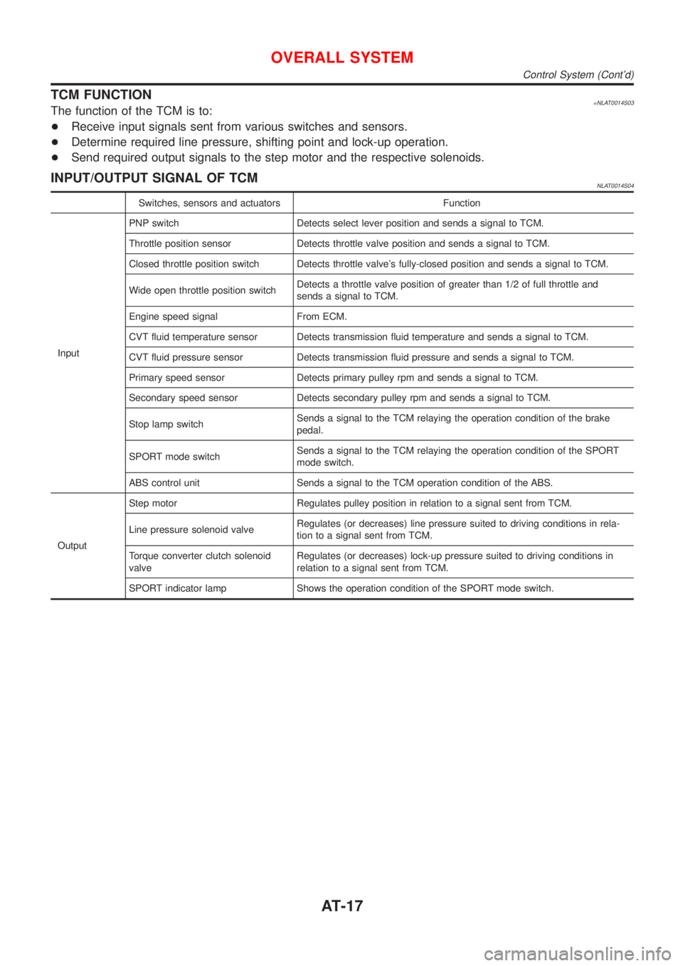
TCM FUNCTION=NLAT0014S03The function of the TCM is to:
+Receive input signals sent from various switches and sensors.
+Determine required line pressure, shifting point and lock-up operation.
+Send required output signals to the step motor and the respective solenoids.
INPUT/OUTPUT SIGNAL OF TCMNLAT0014S04
Switches, sensors and actuators Function
InputPNP switch Detects select lever position and sends a signal to TCM.
Throttle position sensor Detects throttle valve position and sends a signal to TCM.
Closed throttle position switch Detects throttle valve's fully-closed position and sends a signal to TCM.
Wide open throttle position switchDetects a throttle valve position of greater than 1/2 of full throttle and
sends a signal to TCM.
Engine speed signal From ECM.
CVT fluid temperature sensor Detects transmission fluid temperature and sends a signal to TCM.
CVT fluid pressure sensor Detects transmission fluid pressure and sends a signal to TCM.
Primary speed sensor Detects primary pulley rpm and sends a signal to TCM.
Secondary speed sensor Detects secondary pulley rpm and sends a signal to TCM.
Stop lamp switchSends a signal to the TCM relaying the operation condition of the brake
pedal.
SPORT mode switchSends a signal to the TCM relaying the operation condition of the SPORT
mode switch.
ABS control unit Sends a signal to the TCM operation condition of the ABS.
OutputStep motor Regulates pulley position in relation to a signal sent from TCM.
Line pressure solenoid valveRegulates (or decreases) line pressure suited to driving conditions in rela-
tion to a signal sent from TCM.
Torque converter clutch solenoid
valveRegulates (or decreases) lock-up pressure suited to driving conditions in
relation to a signal sent from TCM.
SPORT indicator lamp Shows the operation condition of the SPORT mode switch.
OVERALL SYSTEM
Control System (Cont'd)
AT-17
Page 26 of 3051
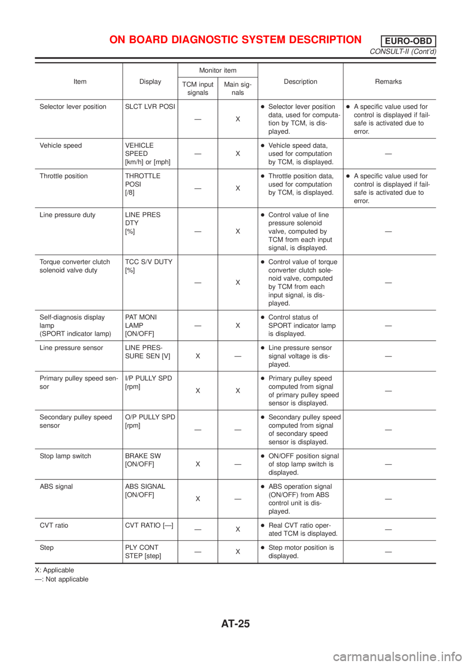
Item DisplayMonitor item
Description Remarks
TCM input
signalsMain sig-
nals
Selector lever position SLCT LVR POSI
ÐX+Selector lever position
data, used for computa-
tion by TCM, is dis-
played.+A specific value used for
control is displayed if fail-
safe is activated due to
error.
Vehicle speed VEHICLE
SPEED
[km/h] or [mph]ÐX+Vehicle speed data,
used for computation
by TCM, is displayed.Ð
Throttle position THROTTLE
POSI
[/8]ÐX+Throttle position data,
used for computation
by TCM, is displayed.+A specific value used for
control is displayed if fail-
safe is activated due to
error.
Line pressure duty LINE PRES
DTY
[%] Ð X+Control value of line
pressure solenoid
valve, computed by
TCM from each input
signal, is displayed.Ð
Torque converter clutch
solenoid valve dutyTCC S/V DUTY
[%]
ÐX+Control value of torque
converter clutch sole-
noid valve, computed
by TCM from each
input signal, is dis-
played.Ð
Self-diagnosis display
lamp
(SPORT indicator lamp)PAT MONI
LAMP
[ON/OFF]ÐX+Control status of
SPORT indicator lamp
is displayed.Ð
Line pressure sensor LINE PRES-
SURE SEN [V] X Ð+Line pressure sensor
signal voltage is dis-
played.Ð
Primary pulley speed sen-
sorI/P PULLY SPD
[rpm]
XX+Primary pulley speed
computed from signal
of primary pulley speed
sensor is displayed.Ð
Secondary pulley speed
sensorO/P PULLY SPD
[rpm]
ÐÐ+Secondary pulley speed
computed from signal
of secondary speed
sensor is displayed.Ð
Stop lamp switch BRAKE SW
[ON/OFF] X Ð+ON/OFF position signal
of stop lamp switch is
displayed.Ð
ABS signal ABS SIGNAL
[ON/OFF]
XÐ+ABS operation signal
(ON/OFF) from ABS
control unit is dis-
played.Ð
CVT ratio CVT RATIO [Ð]
ÐX+Real CVT ratio oper-
ated TCM is displayed.Ð
Step PLY CONT
STEP [step]ÐX+Step motor position is
displayed.Ð
X: Applicable
Ð: Not applicable
ON BOARD DIAGNOSTIC SYSTEM DESCRIPTIONEURO-OBD
CONSULT-II (Cont'd)
AT-25
Page 27 of 3051
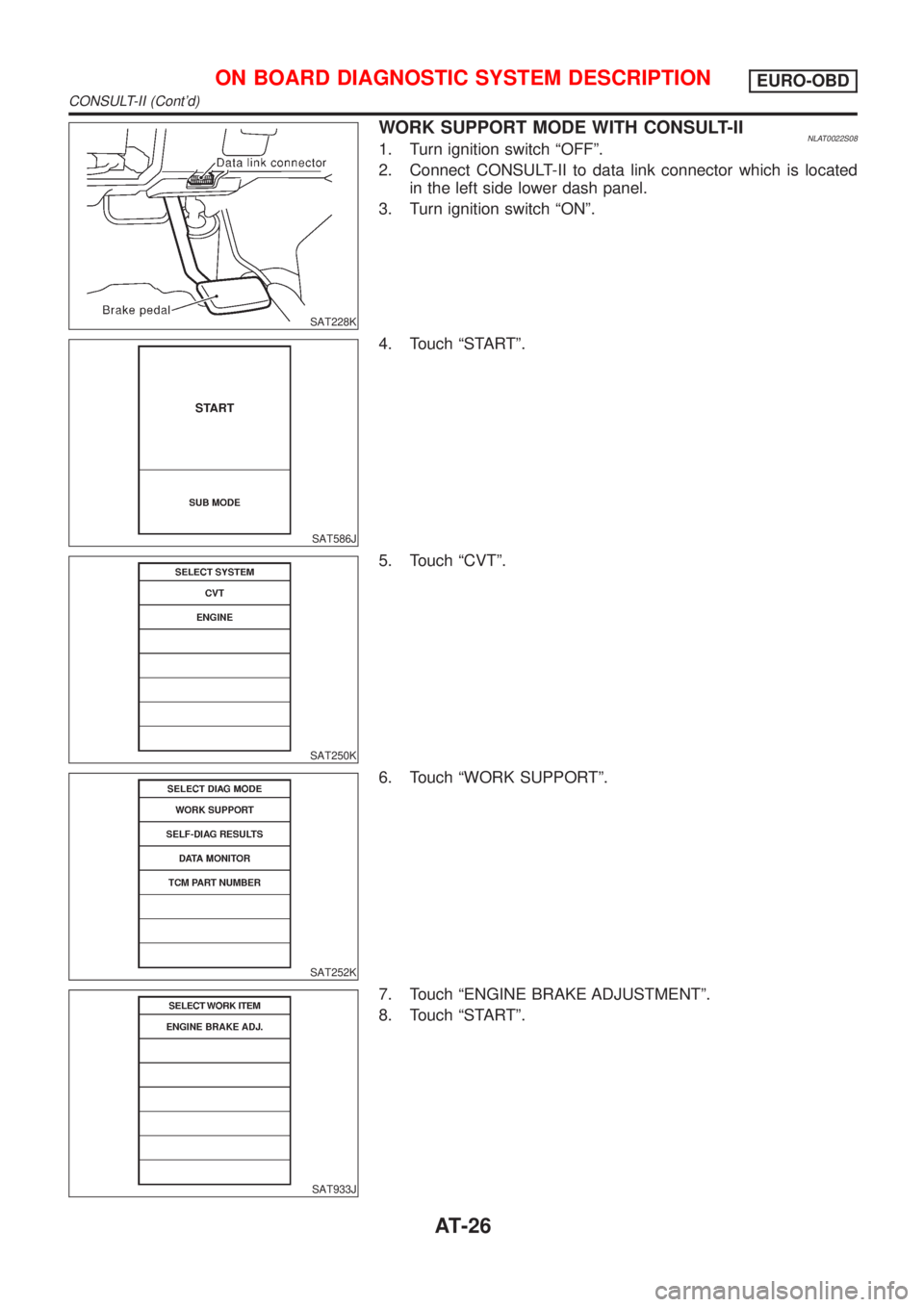
SAT228K
WORK SUPPORT MODE WITH CONSULT-IINLAT0022S081. Turn ignition switch ªOFFº.
2. Connect CONSULT-II to data link connector which is located
in the left side lower dash panel.
3. Turn ignition switch ªONº.
SAT586J
4. Touch ªSTARTº.
SAT250K
5. Touch ªCVTº.
SAT252K
6. Touch ªWORK SUPPORTº.
SAT933J
7. Touch ªENGINE BRAKE ADJUSTMENTº.
8. Touch ªSTARTº.
ON BOARD DIAGNOSTIC SYSTEM DESCRIPTIONEURO-OBD
CONSULT-II (Cont'd)
AT-26
Page 28 of 3051
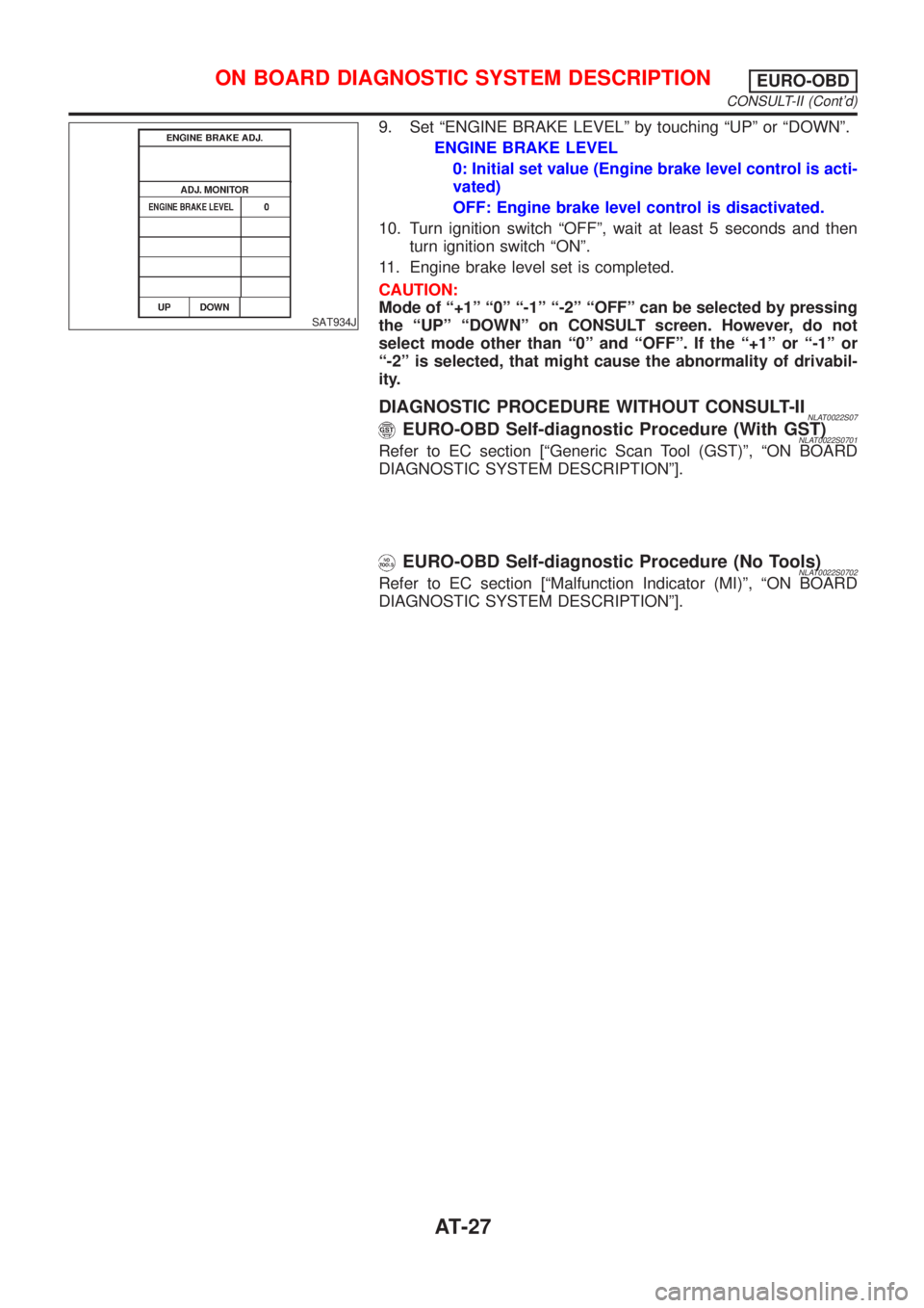
SAT934J
9. Set ªENGINE BRAKE LEVELº by touching ªUPº or ªDOWNº.
ENGINE BRAKE LEVEL
0: Initial set value (Engine brake level control is acti-
vated)
OFF: Engine brake level control is disactivated.
10. Turn ignition switch ªOFFº, wait at least 5 seconds and then
turn ignition switch ªONº.
11. Engine brake level set is completed.
CAUTION:
Mode of ª+1º ª0º ª-1º ª-2º ªOFFº can be selected by pressing
the ªUPº ªDOWNº on CONSULT screen. However, do not
select mode other than ª0º and ªOFFº. If the ª+1º or ª-1º or
ª-2º is selected, that might cause the abnormality of drivabil-
ity.
DIAGNOSTIC PROCEDURE WITHOUT CONSULT-IINLAT0022S07EURO-OBD Self-diagnostic Procedure (With GST)NLAT0022S0701Refer to EC section [ªGeneric Scan Tool (GST)º, ªON BOARD
DIAGNOSTIC SYSTEM DESCRIPTIONº].
EURO-OBD Self-diagnostic Procedure (No Tools)NLAT0022S0702Refer to EC section [ªMalfunction Indicator (MI)º, ªON BOARD
DIAGNOSTIC SYSTEM DESCRIPTIONº].
ON BOARD DIAGNOSTIC SYSTEM DESCRIPTIONEURO-OBD
CONSULT-II (Cont'd)
AT-27
Page 29 of 3051
SAT491J
SAT234K
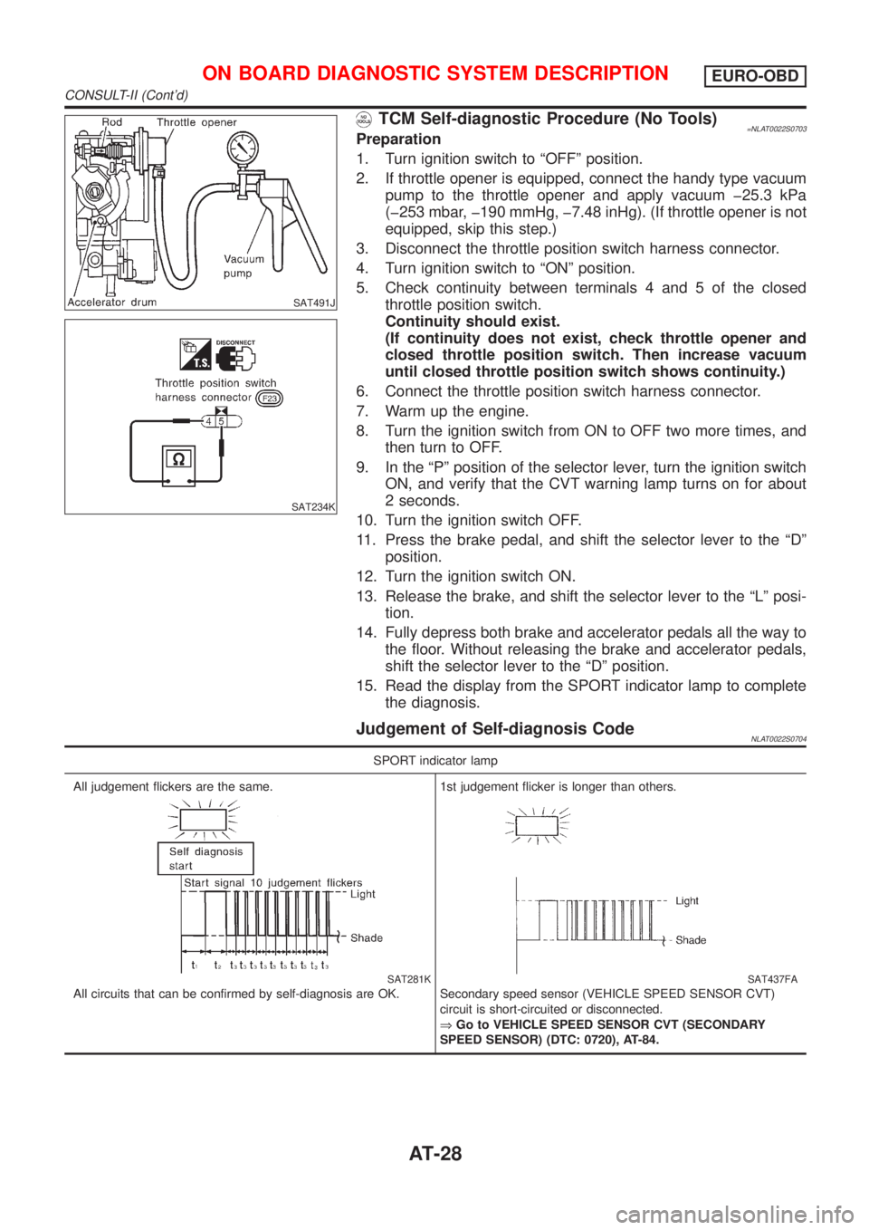
TCM Self-diagnostic Procedure (No Tools)=NLAT0022S0703Preparation
1. Turn ignition switch to ªOFFº position.
2. If throttle opener is equipped, connect the handy type vacuum
pump to the throttle opener and apply vacuum þ25.3 kPa
(þ253 mbar, þ190 mmHg, þ7.48 inHg). (If throttle opener is not
equipped, skip this step.)
3. Disconnect the throttle position switch harness connector.
4. Turn ignition switch to ªONº position.
5. Check continuity between terminals 4 and 5 of the closed
throttle position switch.
Continuity should exist.
(If continuity does not exist, check throttle opener and
closed throttle position switch. Then increase vacuum
until closed throttle position switch shows continuity.)
6. Connect the throttle position switch harness connector.
7. Warm up the engine.
8. Turn the ignition switch from ON to OFF two more times, and
then turn to OFF.
9. In the ªPº position of the selector lever, turn the ignition switch
ON, and verify that the CVT warning lamp turns on for about
2 seconds.
10. Turn the ignition switch OFF.
11. Press the brake pedal, and shift the selector lever to the ªDº
position.
12. Turn the ignition switch ON.
13. Release the brake, and shift the selector lever to the ªLº posi-
tion.
14. Fully depress both brake and accelerator pedals all the way to
the floor. Without releasing the brake and accelerator pedals,
shift the selector lever to the ªDº position.
15. Read the display from the SPORT indicator lamp to complete
the diagnosis.
Judgement of Self-diagnosis CodeNLAT0022S0704
SPORT indicator lamp
All judgement flickers are the same.
SAT281K
All circuits that can be confirmed by self-diagnosis are OK.1st judgement flicker is longer than others.
SAT437FA
Secondary speed sensor (VEHICLE SPEED SENSOR CVT)
circuit is short-circuited or disconnected.
ÞGo to VEHICLE SPEED SENSOR CVT (SECONDARY
SPEED SENSOR) (DTC: 0720), AT-84.
ON BOARD DIAGNOSTIC SYSTEM DESCRIPTIONEURO-OBD
CONSULT-II (Cont'd)
AT-28
Page 35 of 3051
![NISSAN ALMERA TINO 2001 Service Repair Manual Item DisplayMonitor item
Description Remarks
TCM input
signalsMain sig-
nals
Line pressure sensor LINE PRES
SEN [V] X Ð+CVT fluid pressure sen-
sor signal voltage is
displayed.Ð
Primary pulley speed NISSAN ALMERA TINO 2001 Service Repair Manual Item DisplayMonitor item
Description Remarks
TCM input
signalsMain sig-
nals
Line pressure sensor LINE PRES
SEN [V] X Ð+CVT fluid pressure sen-
sor signal voltage is
displayed.Ð
Primary pulley speed](/manual-img/5/57352/w960_57352-34.png)
Item DisplayMonitor item
Description Remarks
TCM input
signalsMain sig-
nals
Line pressure sensor LINE PRES
SEN [V] X Ð+CVT fluid pressure sen-
sor signal voltage is
displayed.Ð
Primary pulley speed sen-
sorI/P PULLY SPD
[rpm]
XX+Primary pulley speed
computed from signal
of primary pulley speed
sensor is displayed.
Secondary pulley speed
sensorO/P PULLY SPD
[rpm]
ÐÐ+Secondary pulley speed
computed from signal
of secondary speed
sensor is displayed.Ð
Stop lamp switch BRAKE SW
[ON/OFF] X Ð+ON/OFF position signal
of stop lamp switch is
displayed.Ð
ABS signal ABS SIGNAL
[ON/OFF]
XÐ+ABS operation signal
(ON/OFF) from ABS
control unit is dis-
played.Ð
CVT ratio CVT RATIO [Ð]
ÐX+Real CVT ratio oper-
ated TCM is displayed.Ð
Step PLY CONT
STEP [step]ÐX+Step motor position is
displayed.Ð
X: Applicable
Ð: Not applicable
SAT250K
HOW TO ERASE SELF-DIAGNOSTIC RESULTS
(
WITH CONSULT-II)NLAT0245S091. If the ignition switch stays ªONº after repair work, be sure to
turn ignition switch ªOFFº once. Wait for at least 3 seconds and
then turn it ªONº again.
2. Turn CONSULT-II ªONº, and touch ªCVTº.
SAT252K
3. Touch ªSELF-DIAG RESULTSº.
ON BOARD DIAGNOSTIC SYSTEM
DESCRIPTION
EXCEPT FOR EURO-OBD
CONSULT-II (Cont'd)
AT-34