Page 4 of 3051

CONTROL UNIT (EEPROM).......................................182
Description ...............................................................182
Diagnostic Procedure ..............................................183
TROUBLE DIAGNOSES FOR NON-DETECTABLE
ITEMS...........................................................................184
PNP Switch, Stop Lamp Switch and Throttle
Position Switch ........................................................184
Diagnostic Procedure ..............................................184
Wiring Diagram - AT - NONDTC .............................188
TROUBLE DIAGNOSES FOR SYMPTOMS...............192
SPORT Indicator Lamp Does Not Come On ..........192
A/T SHIFT LOCK SYSTEM.........................................195
Description ...............................................................195
Shift Lock System Electrical Parts Location............195
Wiring Diagram - SHIFT -........................................196
Diagnostic Procedure ..............................................198
KEY INTERLOCK CABLE..........................................202
Components.............................................................202
Removal ...................................................................202
Installation ................................................................203ON-VEHICLE SERVICE..............................................204
Control Cable Adjustment ........................................204
Park/Neutral Position (PNP) Switch Adjustment .....204
Differential Side Oil Seal Replacement ...................204
REMOVAL AND INSTALLATION...............................206
Removal ...................................................................206
Inspection.................................................................206
Installation ................................................................207
Air Breather Hose ....................................................208
CVT Fluid Cooler .....................................................208
Components.............................................................209
SERVICE DATA AND SPECIFICATIONS (SDS).......210
General Specifications .............................................210
Stall Revolution ........................................................210
Line Pressure...........................................................210
Removal and Installation .........................................210
A/T Fluid Temperature Sensor.................................210
Solenoid Valves .......................................................210
Dropping Resistor ....................................................210
CONTENTS(Cont'd)
AT-3
Page 10 of 3051
Special Service ToolsNLAT0006
Tool number
Tool nameDescription
ST2505S001
Oil pressure gauge set
1 ST25051001
Oil pressure gauge
2 ST25052000
Hose
3 ST25053000
Joint pipe
4 ST25054000
Adapter
5 ST25055000
Adapter
NT097
Measuring line pressure and governor pressure
KV31103000
Drift
NT105
Installing differential side oil seal
(Use with ST35325000)
a: 59 mm (2.32 in) dia.
b: 49 mm (1.93 in) dia.
ST35325000
Drift
NT417
Installing differential side oil seal
(Use with KV31103000)
a: 215 mm (8.46 in)
b: 25 mm (0.98 in) dia.
c: M12 x 1.5P
PREPARATION
Special Service Tools
AT-9
Page 205 of 3051

SAT658J
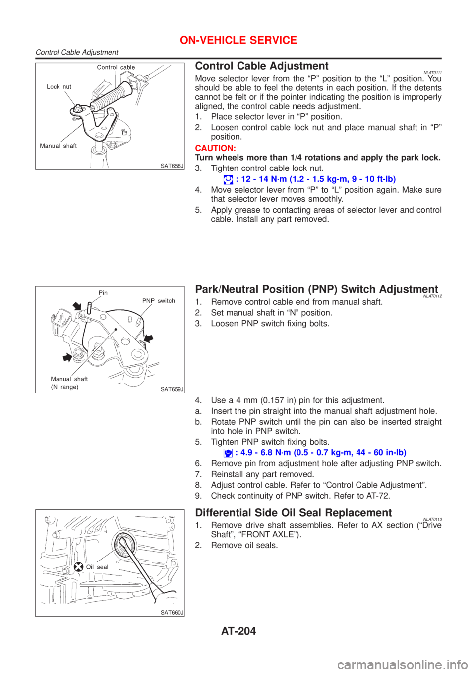
Control Cable AdjustmentNLAT0111Move selector lever from the ªPº position to the ªLº position. You
should be able to feel the detents in each position. If the detents
cannot be felt or if the pointer indicating the position is improperly
aligned, the control cable needs adjustment.
1. Place selector lever in ªPº position.
2. Loosen control cable lock nut and place manual shaft in ªPº
position.
CAUTION:
Turn wheels more than 1/4 rotations and apply the park lock.
3. Tighten control cable lock nut.
: 12 - 14 N´m (1.2 - 1.5 kg-m,9-10ft-lb)
4. Move selector lever from ªPº to ªLº position again. Make sure
that selector lever moves smoothly.
5. Apply grease to contacting areas of selector lever and control
cable. Install any part removed.
SAT659J
Park/Neutral Position (PNP) Switch AdjustmentNLAT01121. Remove control cable end from manual shaft.
2. Set manual shaft in ªNº position.
3. Loosen PNP switch fixing bolts.
4. Usea4mm(0.157 in) pin for this adjustment.
a. Insert the pin straight into the manual shaft adjustment hole.
b. Rotate PNP switch until the pin can also be inserted straight
into hole in PNP switch.
5. Tighten PNP switch fixing bolts.
: 4.9 - 6.8 N´m (0.5 - 0.7 kg-m, 44 - 60 in-lb)
6. Remove pin from adjustment hole after adjusting PNP switch.
7. Reinstall any part removed.
8. Adjust control cable. Refer to ªControl Cable Adjustmentº.
9. Check continuity of PNP switch. Refer to AT-72.
SAT660J
Differential Side Oil Seal ReplacementNLAT01131. Remove drive shaft assemblies. Refer to AX section (ªDrive
Shaftº, ªFRONT AXLEº).
2. Remove oil seals.
ON-VEHICLE SERVICE
Control Cable Adjustment
AT-204
Page 206 of 3051
SAT661JB
3. Install oil seals.
+Apply CVT fluid to oil seal surface before installing.
+Install oil seals so that dimensions ªAº and ªBº are within
specifications.
Unit: mm (in)
AB
5.5 - 6.5 (0.217 - 0.256) þ0.5 to 0.5 (þ0.020 to 0.020)
4. Reinstall any part removed.
ON-VEHICLE SERVICE
Differential Side Oil Seal Replacement (Cont'd)
AT-205
Page 213 of 3051
SBR686C
Precautions
PRECAUTIONSNLAX0001+When installing rubber parts, final tightening must be car-
ried out under unladen condition* with tires on ground.
*: Fuel, radiator coolant and engine oil full. Spare tire, jack,
hand tools and mats in designated positions.
+After installing removed suspension parts, check wheel
alignment and adjust if necessary.
+Use flare nut wrench when removing or installing brake
tubes.
+Always torque brake lines when installing.
Preparation
SPECIAL SERVICE TOOLSNLAX0002
Tool number
Tool nameDescription
HT72520000
Ball joint remover
NT146
Removing tie-rod outer end and lower ball joint
KV38106800
Differential side oil seal
protector
NT147
Installing drive shaft
KV38106800
COMMERCIAL SERVICE TOOLSNLAX0003
Tool name Description
1 Flare nut crowfoot
2 Torque wrench
NT360
Removing and installing each brake piping
a: 10 mm (0.39 in)
FRONT AXLE
Precautions
AX-2
Page 222 of 3051
SFA090A
REMOVALNLAX00141. Remove wheel bearing lock nut.
Brake caliper need not be disconnected. Do not twist or
stretch brake hose when moving components.
SFA153B
2. Remove strut lower mount bolts.
3. Remove brake hose clip.
SFA499A
4. Separate drive shaft from knuckle by lightly tapping it. If it is
hard to remove, use a puller.
Cover boots with shop towel so as not to damage them
when removing drive shaft.
Refer to“Wheel Hub and Knuckle”,“FRONT AXLE”, AX-5.
5. Remove right drive shaft from transaxle.
NAX004
6. Remove left drive shaft from transaxle.
+Pry off drive shaft from transaxle as shown at left.
SFA482-D
INSTALLATIONNLAX0015Transaxle SideNLAX0015S011. Drive a new oil seal to transaxle. Refer to MT-15 or AT-204,
“Replacing Oil Seal”or“Differential Side Oil Seal
Replacement”,“ON-VEHICLE SERVICE”.
2. Set Tool along the inner circumference of oil seal.
FRONT AXLE
Drive Shaft (Cont’d)
AX-11
Page 2403 of 3051
General SpecificationsNLEM0143
Cylinder arrangementIn-line 4
Displacement cm
3(cu in)1,998 (121.92)
Bore and stroke mm (in)86´86 (3.39´3.39)
Valve arrangementDOHC
Firing order1-3-4-2
Number of piston ringsCompression 2
Oil 1
Number of main bearings5
Compression ratio10.0
Valve timing
Unit: degree
EM120
abcde f
232É 240É 6É 54É 3É 49É
Compression PressureNLEM0144Unit: kPa (kg/cm2, psi)/300 rpm
Compression pressureStandard 1,275 (13.01, 184.9)
Minimum 1,079 (11.01, 156.5)
Differential limit between cylinders 98 (1.0, 14)
Cylinder HeadNLEM0147Unit: mm (in)
SEM043F
Standard Limit
Head surface distortion Less than 0.03 (0.0012) 0.1 (0.004)
Nominal cylinder head
height ªHº136.9 - 137.1 (5.390 - 5.398)
Resurfacing limit 0.2 (0.008)*
*Total amount of cylinder head resurfacing plus cylinder block resurfacing
SERVICE DATA AND SPECIFICATIONS (SDS)SR
General Specifications
EM-146
Page 2498 of 3051

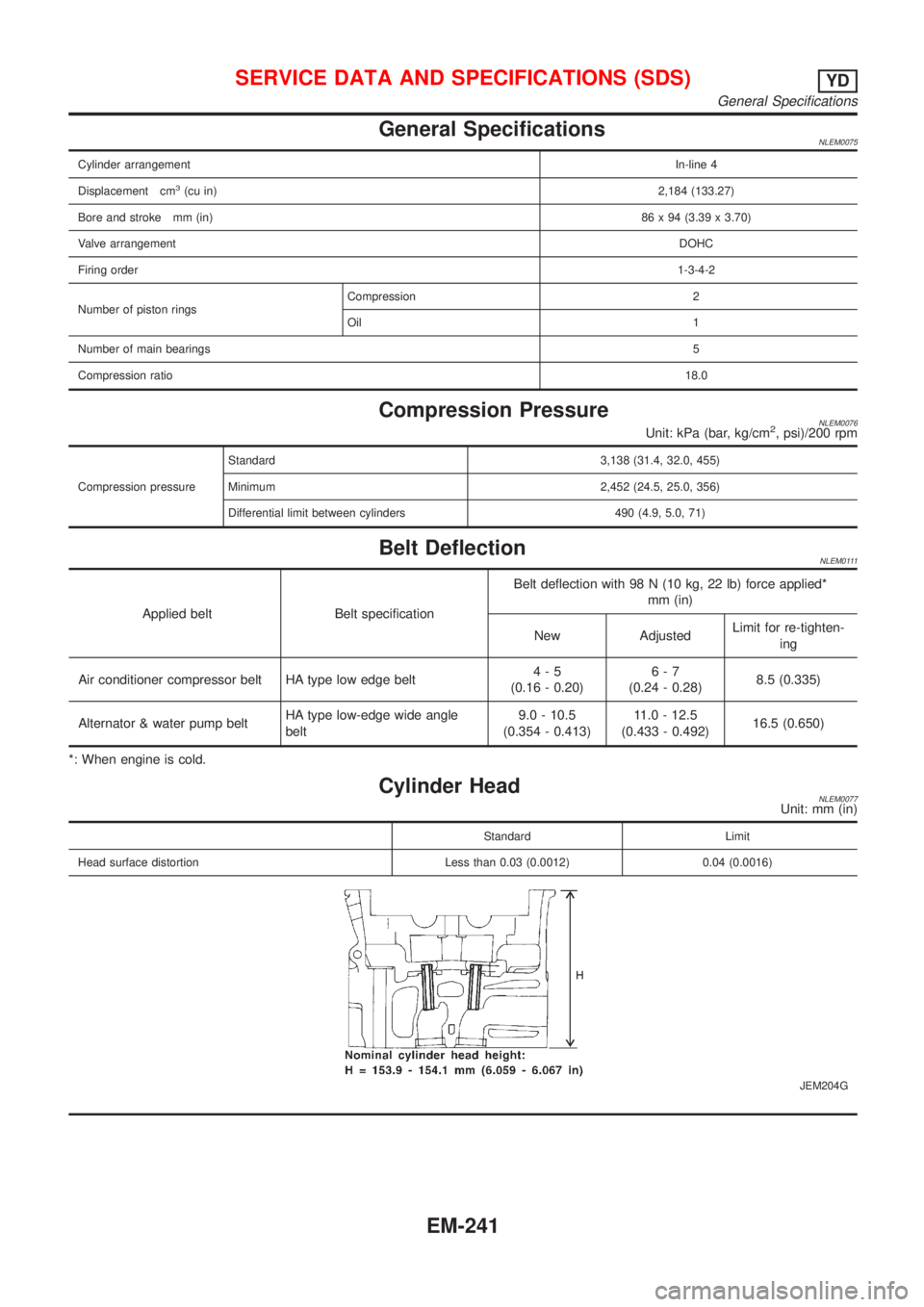
General SpecificationsNLEM0075
Cylinder arrangementIn-line 4
Displacement cm
3(cu in)2,184 (133.27)
Bore and stroke mm (in)86 x 94 (3.39 x 3.70)
Valve arrangementDOHC
Firing order1-3-4-2
Number of piston ringsCompression 2
Oil 1
Number of main bearings5
Compression ratio18.0
Compression PressureNLEM0076Unit: kPa (bar, kg/cm2, psi)/200 rpm
Compression pressureStandard 3,138 (31.4, 32.0, 455)
Minimum 2,452 (24.5, 25.0, 356)
Differential limit between cylinders 490 (4.9, 5.0, 71)
Belt DeflectionNLEM0111
Applied belt Belt specificationBelt deflection with 98 N (10 kg, 22 lb) force applied*
mm (in)
New AdjustedLimit for re-tighten-
ing
Air conditioner compressor belt HA type low edge belt4-5
(0.16 - 0.20)6-7
(0.24 - 0.28)8.5 (0.335)
Alternator & water pump beltHA type low-edge wide angle
belt9.0 - 10.5
(0.354 - 0.413)11.0 - 12.5
(0.433 - 0.492)16.5 (0.650)
*: When engine is cold.
Cylinder HeadNLEM0077Unit: mm (in)
Standard Limit
Head surface distortion Less than 0.03 (0.0012) 0.04 (0.0016)
JEM204G
SERVICE DATA AND SPECIFICATIONS (SDS)YD
General Specifications
EM-241