2001 NISSAN ALMERA TINO tire type
[x] Cancel search: tire typePage 225 of 3051

SFA693
3. Press support bearing assembly off of drive shaft.
SFA617
4. Separate support bearing from retainer.
INSPECTIONNLAX0018Thoroughly clean all parts in cleaning solvent, and dry with
compressed air. Check parts for evidence of deformation or
other damage.
Drive ShaftNLAX0018S01Replace drive shaft if it is twisted or cracked.
BootNLAX0018S02Check boot for fatigue, cracks or wear. Replace boot with new boot
bands.
Joint Assembly (Transaxle side)NLAX0018S03+Check spider assembly for needle bearing and washer dam-
age. Replace if necessary. (Tripod type)
+Check roller surfaces for scratches, wear or other damage.
Replace if necessary. (Tripod type)
+Replace any parts of double offset joint which show signs of
scorching, rust, wear or excessive play. (Double offset type)
+Check serration for deformation. Replace if necessary.
+Check slide joint housing for any damage. Replace if neces-
sary.
Joint Assembly (Wheel side)NLAX0018S04Replace joint assembly if it is deformed or damaged.
Support BearingNLAX0018S05Make sure wheel bearing rolls freely and is free from noise, cracks,
pitting or wear.
Support Bearing BracketNLAX0018S06Check support bearing bracket for cracks with a magnetic explora-
tion or dyeing test.
ASSEMBLYNLAX0019+After drive shaft has been assembled, ensure that it
moves smoothly over its entire range without binding.
FRONT AXLE
Drive Shaft (Cont’d)
AX-14
Page 2907 of 3051

Precautions
SUPPLEMENTAL RESTRAINT SYSTEM (SRS)“AIR BAG”AND“SEAT BELT
PRE-TENSIONER”
NLRS0006The Supplemental Restraint System such as“AIR BAG”and“SEAT BELT PRE-TENSIONER”used along with
a seat belt, helps to reduce the risk or severity of injury to the driver and front passenger for certain types of
collision. The SRS composition which is available to NISSAN MODEL V10 is as follows (The composition var-
ies according to the destination and optional equipment.):
+For a frontal collision
The Supplemental Restraint System consists of driver air bag module (located in the center of the steer-
ing wheel), front passenger air bag module (located on the instrument panel on passenger side), front seat
belt pre-tensioners, a diagnosis sensor unit, warning lamp, wiring harness and spiral cable.
+For a side collision
The Supplemental Restraint System consists of front side air bag module (located in the outer side of front
seat), side air bag (satellite) sensor, diagnosis sensor unit (one of components of air bags for a frontal
collision), wiring harness, warning lamp (one of components of air bags for a frontal collision).
WARNING:
+To avoid rendering the SRS inoperative, which could increase the risk of personal injury or death
in the event of a collision which would result in air bag inflation, all maintenance should be per-
formed by an authorized NISSAN dealer.
+Improper maintenance, including incorrect removal and installation of the SRS, can lead to per-
sonal injury caused by unintentional activation of the system.
+Do not use electrical test equipment on any circuit related to the SRS unless instructed to in this
Service Manual. Spiral cable and wiring harnesses covered with yellow insulation tape either just
before the harness connectors or for the complete harness are related to the SRS.
PRECAUTIONS FOR SRS“AIR BAG”AND“SEAT BELT PRE-TENSIONER”SERVICENLRS0007+Do not use electrical test equipment to check SRS circuits unless instructed to in this Service Manual.
+Before servicing the SRS, turn ignition switch“OFF”, disconnect both battery cables and wait at least 3
minutes.
For approximately 3 minutes after the cables are removed, it is still possible for the air bag and seat belt
pre-tensioner to deploy. Therefore, do not work on any SRS connectors or wires until at least 3 minutes
have passed.
+Diagnosis sensor unit must always be installed with their arrow marks“⇐”pointing towards the front of
the vehicle for proper operation. Also check diagnosis sensor unit for cracks, deformities or rust before
installation and replace as required.
+The spiral cable must be aligned with the neutral position since its rotations are limited. Do not attempt to
turn steering wheel or column after removal of steering gear.
+Handle air bag module carefully. Always place driver and front passenger air bag modules with the pad
side facing upward and place front side air bag module (built-in type) standing with stud bolt side setting
bottom.
+Conduct self-diagnosis to check entire SRS for proper function after replacing any components.
+After air bag inflates, the front instrument panel assembly should be replaced if damaged.
WIRING DIAGRAMS AND TROUBLE DIAGNOSISNLRS0008When you read wiring diagrams, refer to the following:
+GI-11,“HOW TO READ WIRING DIAGRAMS”
+EL-10,“POWER SUPPLY ROUTING”for power distribution circuit
When you perform trouble diagnosis, refer to the following:
+GI-32,“HOW TO FOLLOW TEST GROUPS IN TROUBLE DIAGNOSIS”
+GI-21,“HOW TO PERFORM EFFICIENT DIAGNOSES FOR AN ELECTRICAL INCIDENT”
SUPPLEMENTAL RESTRAINT SYSTEM (SRS)
Precautions
RS-16
Page 3031 of 3051

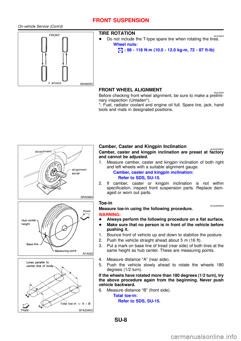
SMA829C
TIRE ROTATIONNLSU0043+Do not include the T-type spare tire when rotating the tires.
Wheel nuts:
:98-118N·m (10.0 - 12.0 kg-m, 72 - 87 ft-lb)
FRONT WHEEL ALIGNMENTNLSU0045Before checking front wheel alignment, be sure to make a prelimi-
nary inspection (Unladen*).
*: Fuel, radiator coolant and engine oil full. Spare tire, jack, hand
tools and mats in designated positions.
SRA096A
Camber, Caster and Kingpin InclinationNLSU0045S01Camber, caster and kingpin inclination are preset at factory
and cannot be adjusted.
1. Measure camber, caster and kingpin inclination of both right
and left wheels with a suitable alignment gauge.
Camber, caster and kingpin inclination:
Refer to SDS, SU-15.
2. If camber, caster or kingpin inclination is not within
specification, inspect front suspension parts. Replace dam-
aged or worn out parts.
AFA050
Toe-inNLSU0045S02Measure toe-in using the following procedure.
WARNING:
+Always perform the following procedure on a flat surface.
+Make sure that no person is in front of the vehicle before
pushing it.
1. Bounce front of vehicle up and down to stabilize the posture.
2. Push the vehicle straight ahead about 5 m (16 ft).
3. Put a mark on base line of tread (rear side) of both tires at the
same height as hub center. These are measuring points.
SFA234AC
4. Measure distance“A”(rear side).
5. Push the vehicle slowly ahead to rotate the wheels 180
degrees (1/2 turn).
If the wheels have rotated more than 180 degrees (1/2 turn), try
the above procedure again from the beginning. Never push
vehicle backward.
6. Measure distance“B”(front side).
Total toe-in:
Refer to SDS, SU-15.
FRONT SUSPENSION
On-vehicle Service (Cont’d)
SU-8
Page 3038 of 3051

Service Data and Specifications (SDS)
GENERAL SPECIFICATIONS (FRONT)=NLSU0020
Suspension type Independent MacPherson strut
Shock absorber type Double-acting hydraulic
Stabilizer barStandard equipment
FRONT WHEEL ALIGNMENT (UNLADEN*1)NLSU0021
QG/SR engine YD engine
Camber
Degree minute (Decimal degree)Minimum �1°05′(�1.08°)
Nominal �0°20′(�0.33°)
Maximum 0°25′(0.42°)
Left and right difference 45′(0.75°)
Caster
Degree minute (Decimal degree)Minimum 2°04′(2.07°) 2°01′(2.02°)
Nominal 2°49′(2.82°) 2°46′(2.77°)
Maximum 3°34′(3.57°) 3°31′(3.52°)
Left and right difference 45′(0.75°)
Kingpin inclination
Degree minute (Decimal degree)Minimum 13°40′(13.67°)
Nominal 14°25′(14.42°)
Maximum 15°10′(°15.17)
Total toe-inDistance (A � B)
mm (in)Minimum 1 (0.04)
Nominal 2 (0.08)
Maximum 3 (0.12)
Angle (left plus right)
Degree minute (Decimal degree)Minimum 0°01′(0.02°)
Nominal 0°04′(0.07°)
Maximum 0°07′(0.12°)
Wheel turning angle
Full turn*2Inside
Degree minute (Decimal degree)Minimum 34°30′(34.50°)
Nominal 38°00′(38.00°)
Maximum 39°00′(39.00°)
Outside
Degree minute (Decimal degree)Nominal 31°00′(31.00°)
*1: Fuel, radiator coolant and engine oil full. Spare tire, jack, hand tools and mats in designated positions.
*2: On power steering models, wheel turning force (at circumference of steering wheel) of 98 to 147 N (10 to 15 kg, 22 to 33 lb) with
engine idle.
*3: “Ground clearance up” model
LOWER BALL JOINTNLSU0022
Swinging force “A”
(Measuring point: cotter pin hole of ball stud) N (kg, lb)7.8 - 82.4 (0.8 - 8.4, 1.8 - 18.5)
Turning torque “B” N·m (kg-cm, in-lb) 0.50 - 4.90 (5.1 - 50.0, 4.4 - 43.4)
Vertical end play “C” mm (in)0 (0)
FRONT SUSPENSION
Service Data and Specifications (SDS)
SU-15
Page 3039 of 3051

WHEELARCH HEIGHT (UNLADEN*1)NLSU0041
SFA818A
195/65R15 205/55R16
QG18 SR20 YD22 QG18 SR20 YD22
FR RR FR RR FR RR FR RR FR RR FR RR
702
(27.64)672
(26.46)700
(27.56)672
(26.46)699
(27.52)672
(26.46)702
(27.64)671
(26.42)701
(27.60)672
(26.46)699
(27.52)671
(26.42)
*1: Fuel, radiator coolant and engine oil full. Spare tire, jack, hand tools and mats in designated positions.
*2:“Ground clearance up”model
WHEEL RUNOUTNLSU0023
Wheel typeAluminum Steel wheel
Radial runout limit mm (in) 0.3 (0.012) 0.5 (0.020)
Lateral runout limit mm (in) 0.3 (0.012) 0.8 (0.031)
WHEEL BALANCENLSU0044
Maximum allowable unbalanceDynamic (At rim flange) g (oz) 10 (0.35) (one side)
Static g (oz) 20 (0.71)
FRONT SUSPENSION
Service Data and Specifications (SDS) (Cont’d)
SU-16
Page 3050 of 3051

Service Data and Specifications (SDS)
GENERAL SPECIFICATIONS (REAR)=NLSU0039
Suspension type Multi-link beam suspension
Shock absorber type Double-acting hydraulic
REAR WHEEL ALIGNMENT (UNLADEN*)NLSU0040
Body
Camber
Degree minute (Decimal degree)Minimum�1°45′(�1.75°)
Nominal�1°00′(�1.00°)
Maximum�0°15′(�0.25°)
Total toe-in Distance (A�B)
mm (in)Minimum�3(�0.12)
Nominal 1 (0.04)
Maximum 5 (0.20)
Angle (left plus right)
Degree minute (Decimal degree)Minimum�16′(�0.27°)
Nominal 5′30″(0.09°)
Maximum 26′(0.43°)
*: Fuel, radiator coolant and engine oil full. Spare tire, jack, hand tools and mats in designated positions.
REAR SUSPENSION
Service Data and Specifications (SDS)
SU-27