2001 NISSAN ALMERA TINO p0325
[x] Cancel search: p0325Page 428 of 3051
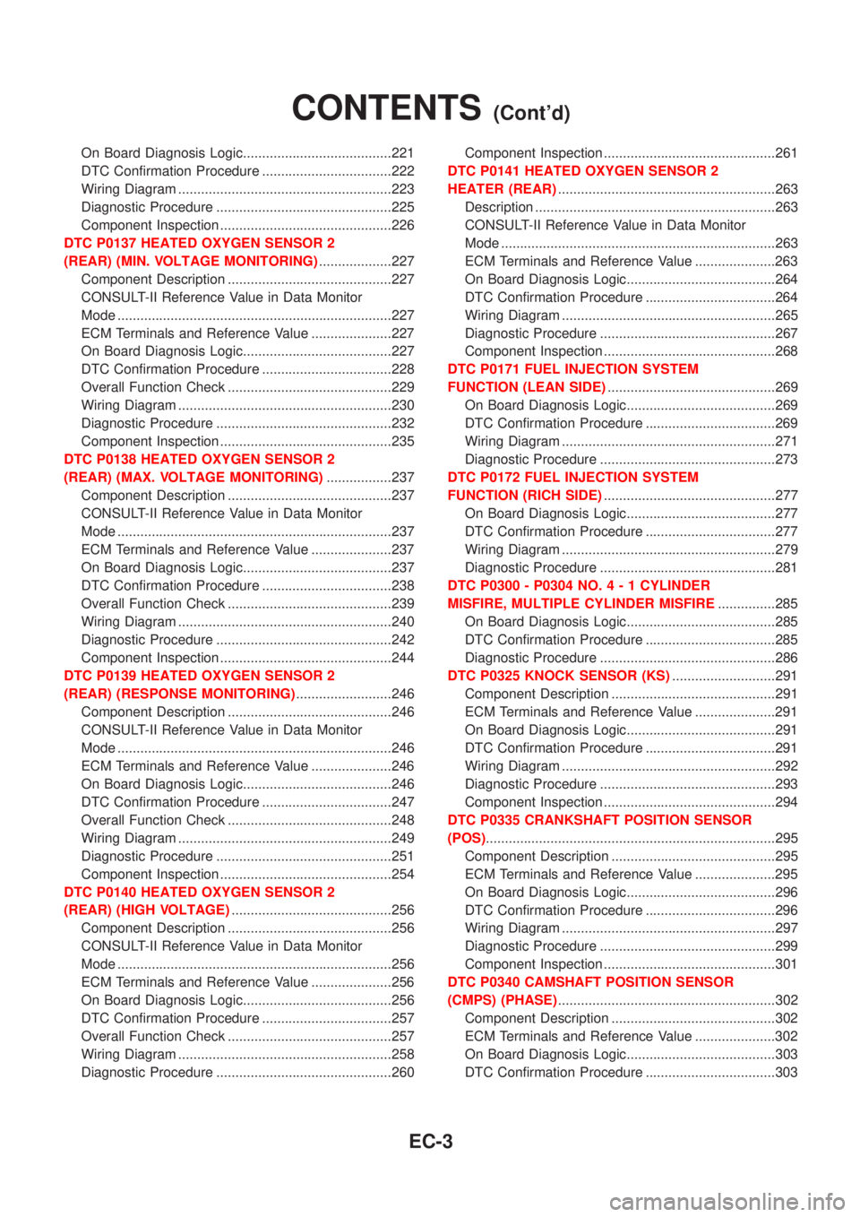
On Board Diagnosis Logic.......................................221
DTC Confirmation Procedure ..................................222
Wiring Diagram ........................................................223
Diagnostic Procedure ..............................................225
Component Inspection .............................................226
DTC P0137 HEATED OXYGEN SENSOR 2
(REAR) (MIN. VOLTAGE MONITORING)...................227
Component Description ...........................................227
CONSULT-II Reference Value in Data Monitor
Mode ........................................................................227
ECM Terminals and Reference Value .....................227
On Board Diagnosis Logic.......................................227
DTC Confirmation Procedure ..................................228
Overall Function Check ...........................................229
Wiring Diagram ........................................................230
Diagnostic Procedure ..............................................232
Component Inspection .............................................235
DTC P0138 HEATED OXYGEN SENSOR 2
(REAR) (MAX. VOLTAGE MONITORING).................237
Component Description ...........................................237
CONSULT-II Reference Value in Data Monitor
Mode ........................................................................237
ECM Terminals and Reference Value .....................237
On Board Diagnosis Logic.......................................237
DTC Confirmation Procedure ..................................238
Overall Function Check ...........................................239
Wiring Diagram ........................................................240
Diagnostic Procedure ..............................................242
Component Inspection .............................................244
DTC P0139 HEATED OXYGEN SENSOR 2
(REAR) (RESPONSE MONITORING).........................246
Component Description ...........................................246
CONSULT-II Reference Value in Data Monitor
Mode ........................................................................246
ECM Terminals and Reference Value .....................246
On Board Diagnosis Logic.......................................246
DTC Confirmation Procedure ..................................247
Overall Function Check ...........................................248
Wiring Diagram ........................................................249
Diagnostic Procedure ..............................................251
Component Inspection .............................................254
DTC P0140 HEATED OXYGEN SENSOR 2
(REAR) (HIGH VOLTAGE)..........................................256
Component Description ...........................................256
CONSULT-II Reference Value in Data Monitor
Mode ........................................................................256
ECM Terminals and Reference Value .....................256
On Board Diagnosis Logic.......................................256
DTC Confirmation Procedure ..................................257
Overall Function Check ...........................................257
Wiring Diagram ........................................................258
Diagnostic Procedure ..............................................260Component Inspection .............................................261
DTC P0141 HEATED OXYGEN SENSOR 2
HEATER (REAR).........................................................263
Description ...............................................................263
CONSULT-II Reference Value in Data Monitor
Mode ........................................................................263
ECM Terminals and Reference Value .....................263
On Board Diagnosis Logic.......................................264
DTC Confirmation Procedure ..................................264
Wiring Diagram ........................................................265
Diagnostic Procedure ..............................................267
Component Inspection .............................................268
DTC P0171 FUEL INJECTION SYSTEM
FUNCTION (LEAN SIDE)............................................269
On Board Diagnosis Logic.......................................269
DTC Confirmation Procedure ..................................269
Wiring Diagram ........................................................271
Diagnostic Procedure ..............................................273
DTC P0172 FUEL INJECTION SYSTEM
FUNCTION (RICH SIDE).............................................277
On Board Diagnosis Logic.......................................277
DTC Confirmation Procedure ..................................277
Wiring Diagram ........................................................279
Diagnostic Procedure ..............................................281
DTC P0300 - P0304 NO.4-1CYLINDER
MISFIRE, MULTIPLE CYLINDER MISFIRE...............285
On Board Diagnosis Logic.......................................285
DTC Confirmation Procedure ..................................285
Diagnostic Procedure ..............................................286
DTC P0325 KNOCK SENSOR (KS)...........................291
Component Description ...........................................291
ECM Terminals and Reference Value .....................291
On Board Diagnosis Logic.......................................291
DTC Confirmation Procedure ..................................291
Wiring Diagram ........................................................292
Diagnostic Procedure ..............................................293
Component Inspection .............................................294
DTC P0335 CRANKSHAFT POSITION SENSOR
(POS)............................................................................295
Component Description ...........................................295
ECM Terminals and Reference Value .....................295
On Board Diagnosis Logic.......................................296
DTC Confirmation Procedure ..................................296
Wiring Diagram ........................................................297
Diagnostic Procedure ..............................................299
Component Inspection .............................................301
DTC P0340 CAMSHAFT POSITION SENSOR
(CMPS) (PHASE).........................................................302
Component Description ...........................................302
ECM Terminals and Reference Value .....................302
On Board Diagnosis Logic.......................................303
DTC Confirmation Procedure ..................................303
CONTENTS(Cont'd)
EC-3
Page 434 of 3051
Wiring Diagram ........................................................764
Diagnostic Procedure ..............................................766
Component Inspection .............................................769
DTC P0139 HEATED OXYGEN SENSOR 2
(REAR) (RESPONSE MONITORING).........................770
Component Description ...........................................770
CONSULT-II Reference Value in Data Monitor
Mode ........................................................................770
ECM Terminals and Reference Value .....................770
On Board Diagnosis Logic.......................................770
DTC Confirmation Procedure ..................................771
Overall Function Check ...........................................772
Wiring Diagram ........................................................773
Diagnostic Procedure ..............................................775
Component Inspection .............................................778
DTC P0140 HEATED OXYGEN SENSOR 2
(REAR) (HIGH VOLTAGE)..........................................779
Component Description ...........................................779
CONSULT-II Reference Value in Data Monitor
Mode ........................................................................779
ECM Terminals and Reference Value .....................779
On Board Diagnosis Logic.......................................779
DTC Confirmation Procedure ..................................780
Overall Function Check ...........................................780
Wiring Diagram ........................................................781
Diagnostic Procedure ..............................................783
Component Inspection .............................................784
DTC P0141 HEATED OXYGEN SENSOR 2
HEATER (REAR).........................................................786
Description ...............................................................786
CONSULT-II Reference Value in Data Monitor
Mode ........................................................................786
ECM Terminals and Reference Value .....................786
On Board Diagnosis Logic.......................................786
DTC Confirmation Procedure ..................................787
Wiring Diagram ........................................................788
Diagnostic Procedure ..............................................790
Component Inspection .............................................791
DTC P0171 FUEL INJECTION SYSTEM
FUNCTION (LEAN SIDE)............................................792
On Board Diagnosis Logic.......................................792
DTC Confirmation Procedure ..................................792
Wiring Diagram ........................................................794
Diagnostic Procedure ..............................................796
DTC P0172 FUEL INJECTION SYSTEM
FUNCTION (RICH SIDE).............................................800
On Board Diagnosis Logic.......................................800
DTC Confirmation Procedure ..................................800
Wiring Diagram ........................................................802
Diagnostic Procedure ..............................................804DTC P0300 - P0304 NO.4-1CYLINDER
MISFIRE, MULTIPLE CYLINDER MISFIRE...............808
On Board Diagnosis Logic.......................................808
DTC Confirmation Procedure ..................................808
Diagnostic Procedure ..............................................809
Component Inspection .............................................814
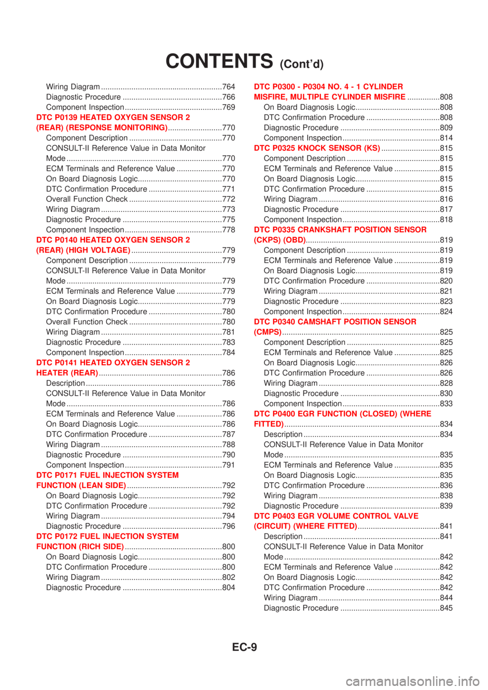
DTC P0325 KNOCK SENSOR (KS)...........................815
Component Description ...........................................815
ECM Terminals and Reference Value .....................815
On Board Diagnosis Logic.......................................815
DTC Confirmation Procedure ..................................815
Wiring Diagram ........................................................816
Diagnostic Procedure ..............................................817
Component Inspection .............................................818
DTC P0335 CRANKSHAFT POSITION SENSOR
(CKPS) (OBD)..............................................................819
Component Description ...........................................819
ECM Terminals and Reference Value .....................819
On Board Diagnosis Logic.......................................819
DTC Confirmation Procedure ..................................820
Wiring Diagram ........................................................821
Diagnostic Procedure ..............................................823
Component Inspection .............................................824
DTC P0340 CAMSHAFT POSITION SENSOR
(CMPS).........................................................................825
Component Description ...........................................825
ECM Terminals and Reference Value .....................825
On Board Diagnosis Logic.......................................826
DTC Confirmation Procedure ..................................826
Wiring Diagram ........................................................828
Diagnostic Procedure ..............................................830
Component Inspection .............................................833
DTC P0400 EGR FUNCTION (CLOSED) (WHERE
FITTED)........................................................................834
Description ...............................................................834
CONSULT-II Reference Value in Data Monitor
Mode ........................................................................835
ECM Terminals and Reference Value .....................835
On Board Diagnosis Logic.......................................835
DTC Confirmation Procedure ..................................836
Wiring Diagram ........................................................838
Diagnostic Procedure ..............................................839
DTC P0403 EGR VOLUME CONTROL VALVE
(CIRCUIT) (WHERE FITTED)......................................841
Description ...............................................................841
CONSULT-II Reference Value in Data Monitor
Mode ........................................................................842
ECM Terminals and Reference Value .....................842
On Board Diagnosis Logic.......................................842
DTC Confirmation Procedure ..................................842
Wiring Diagram ........................................................844
Diagnostic Procedure ..............................................845
CONTENTS(Cont'd)
EC-9
Page 442 of 3051
Items
(CONSULT-II screen terms)DTC*6
Reference page
CONSULT-II
GST*2ECM*1
HO2S2 HTR (B1) P0141 0141 EC-263
IACV/AAC VLV/CIRC P0505 0505 EC-343
INT/V TIM V/CIR-B1 P1111 1111EC-360
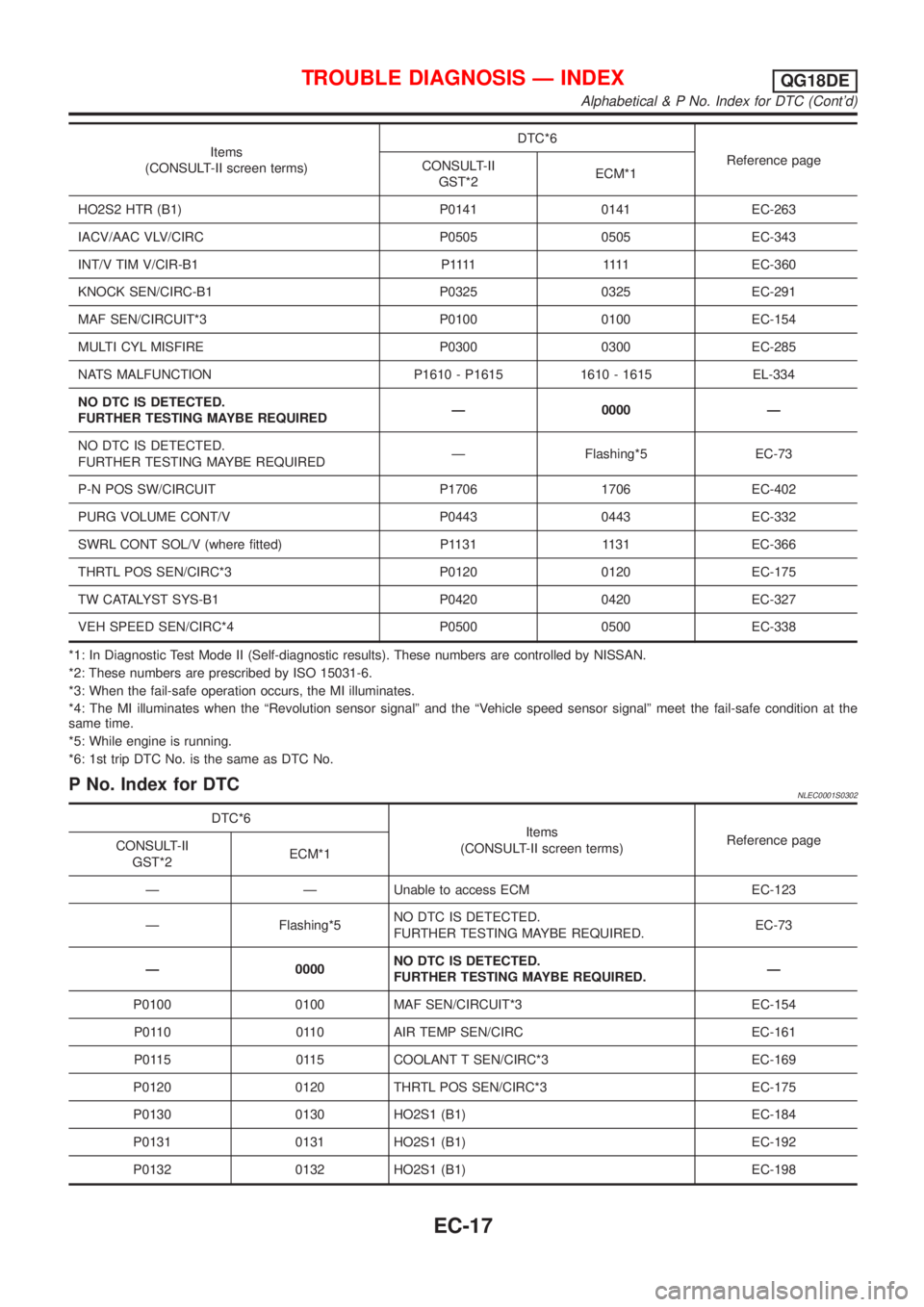
KNOCK SEN/CIRC-B1 P0325 0325 EC-291
MAF SEN/CIRCUIT*3 P0100 0100 EC-154
MULTI CYL MISFIRE P0300 0300 EC-285
NATS MALFUNCTION P1610 - P1615 1610 - 1615 EL-334
NO DTC IS DETECTED.
FURTHER TESTING MAYBE REQUIREDÐ 0000 Ð
NO DTC IS DETECTED.
FURTHER TESTING MAYBE REQUIREDÐ Flashing*5 EC-73
P-N POS SW/CIRCUIT P1706 1706 EC-402
PURG VOLUME CONT/V P0443 0443 EC-332
SWRL CONT SOL/V (where fitted) P1131 1131 EC-366
THRTL POS SEN/CIRC*3 P0120 0120 EC-175
TW CATALYST SYS-B1 P0420 0420 EC-327
VEH SPEED SEN/CIRC*4 P0500 0500 EC-338
*1: In Diagnostic Test Mode II (Self-diagnostic results). These numbers are controlled by NISSAN.
*2: These numbers are prescribed by ISO 15031-6.
*3: When the fail-safe operation occurs, the MI illuminates.
*4: The MI illuminates when the ªRevolution sensor signalº and the ªVehicle speed sensor signalº meet the fail-safe condition at the
same time.
*5: While engine is running.
*6: 1st trip DTC No. is the same as DTC No.
P No. Index for DTCNLEC0001S0302
DTC*6
Items
(CONSULT-II screen terms)Reference page
CONSULT-II
GST*2ECM*1
Ð Ð Unable to access ECM EC-123
Ð Flashing*5NO DTC IS DETECTED.
FURTHER TESTING MAYBE REQUIRED.EC-73
Ð 0000NO DTC IS DETECTED.
FURTHER TESTING MAYBE REQUIRED.Ð
P0100 0100 MAF SEN/CIRCUIT*3 EC-154
P0110 0110 AIR TEMP SEN/CIRC EC-161
P0115 0115 COOLANT T SEN/CIRC*3 EC-169
P0120 0120 THRTL POS SEN/CIRC*3 EC-175
P0130 0130 HO2S1 (B1) EC-184
P0131 0131 HO2S1 (B1) EC-192
P0132 0132 HO2S1 (B1) EC-198
TROUBLE DIAGNOSIS Ð INDEXQG18DE
Alphabetical & P No. Index for DTC (Cont'd)
EC-17
Page 443 of 3051
DTC*6
Items
(CONSULT-II screen terms)Reference page
CONSULT-II
GST*2ECM*1
P0133 0133 HO2S1 (B1) EC-204
P0134 0134 HO2S1 (B1) EC-214
P0135 0135 HO2S1 HTR (B1) EC-221
P0137 0137 HO2S2 (B1) EC-227
P0138 0138 HO2S2 (B1) EC-237
P0139 0139 HO2S2 (B1) EC-246
P0140 0140 HO2S2 (B1) EC-256
P0141 0141 HO2S2 HTR (B1) EC-263
P0171 0171 FUEL SYS-LEAN/BK1 EC-269
P0172 0172 FUEL SYS-RICH/BK1 EC-277
P0300 0300 MULTI CYL MISFIRE EC-285
P0301 0301 CYL 1 MISFIRE EC-285
P0302 0302 CYL 2 MISFIRE EC-285
P0303 0303 CYL 3 MISFIRE EC-285
P0304 0304 CYL 4 MISFIRE EC-285
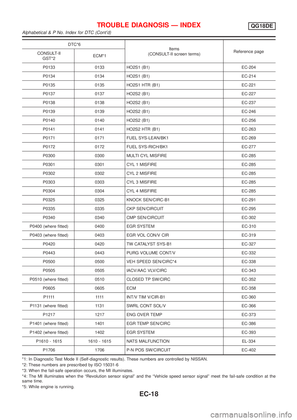
P0325 0325 KNOCK SEN/CIRC-B1 EC-291
P0335 0335 CKP SEN/CIRCUIT EC-295
P0340 0340 CMP SEN/CIRCUIT EC-302
P0400 (where fitted) 0400 EGR SYSTEM EC-310
P0403 (where fitted) 0403 EGR VOL CON/V CIR EC-319
P0420 0420 TW CATALYST SYS-B1 EC-327
P0443 0443 PURG VOLUME CONT/V EC-332
P0500 0500 VEH SPEED SEN/CIRC*4 EC-338
P0505 0505 IACV/AAC VLV/CIRC EC-343
P0510 (where fitted) 0510 CLOSED TP SW/CIRC EC-352
P0605 0605 ECM EC-358
P 1111 1111INT/V TIM V/CIR-B1 EC-360
P1131 (where fitted) 1131 SWRL CONT SOL/V EC-366
P1217 1217 ENG OVER TEMP EC-373
P1401 (where fitted) 1401 EGR TEMP SEN/CIRC EC-386
P1402 (where fitted) 1402 EGR SYSTEM EC-393
P1610 - 1615 1610 - 1615 NATS MALFUNCTION EL-334
P1706 1706 P-N POS SW/CIRCUIT EC-402
*1: In Diagnostic Test Mode II (Self-diagnostic results). These numbers are controlled by NISSAN.
*2: These numbers are prescribed by ISO 15031-6
*3: When the fail-safe operation occurs, the MI illuminates.
*4: The MI illuminates when the ªRevolution sensor signalº and the ªVehicle speed sensor signalº meet the fail-safe condition at the
same time.
*5: While engine is running.
TROUBLE DIAGNOSIS Ð INDEXQG18DE
Alphabetical & P No. Index for DTC (Cont'd)
EC-18
Page 444 of 3051
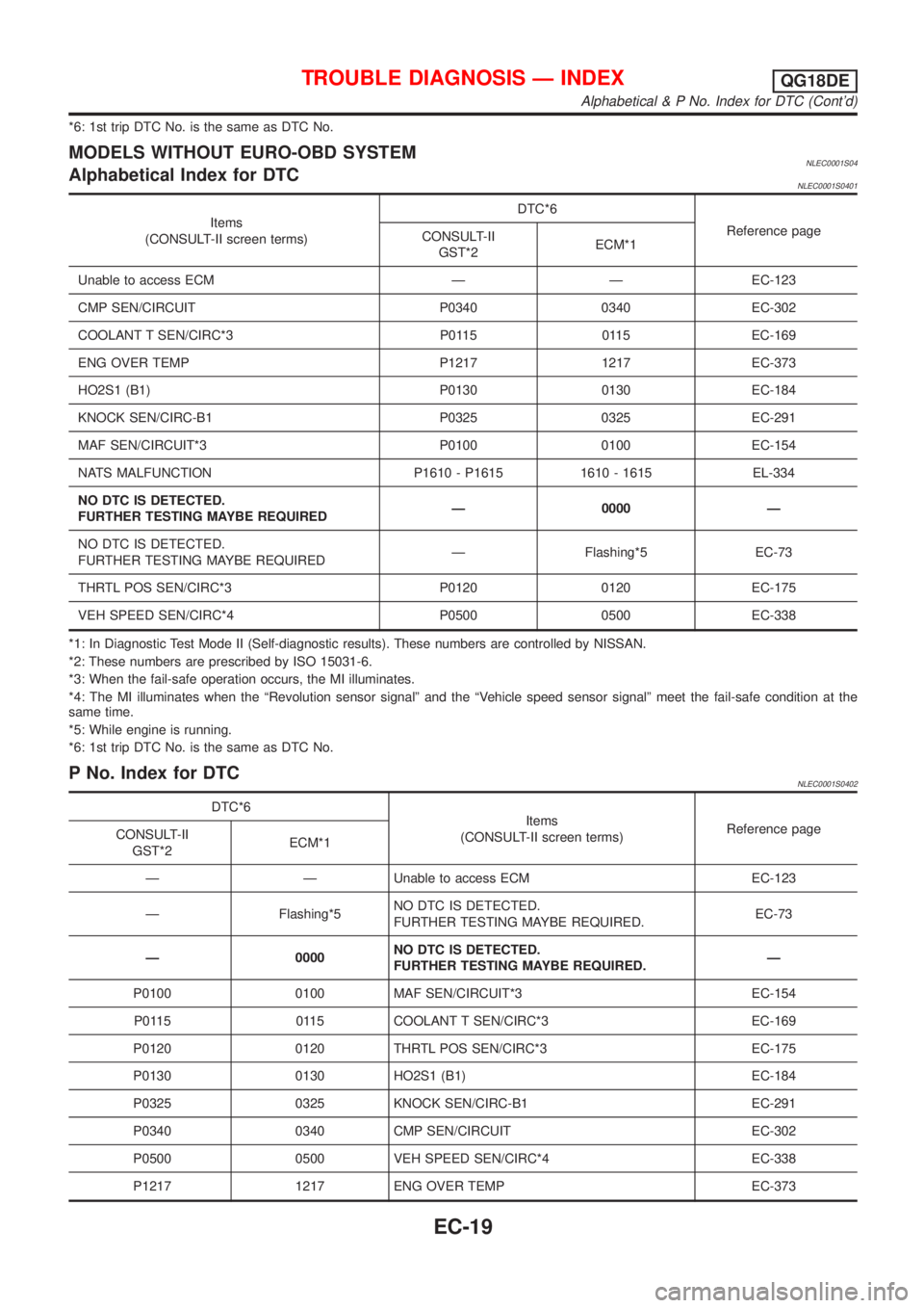
*6: 1st trip DTC No. is the same as DTC No.
MODELS WITHOUT EURO-OBD SYSTEMNLEC0001S04Alphabetical Index for DTCNLEC0001S0401
Items
(CONSULT-II screen terms)DTC*6
Reference page
CONSULT-II
GST*2ECM*1
Unable to access ECM Ð Ð EC-123
CMP SEN/CIRCUIT P0340 0340 EC-302
COOLANT T SEN/CIRC*3 P0115 0115 EC-169
ENG OVER TEMP P1217 1217 EC-373
HO2S1 (B1) P0130 0130 EC-184
KNOCK SEN/CIRC-B1 P0325 0325 EC-291
MAF SEN/CIRCUIT*3 P0100 0100 EC-154
NATS MALFUNCTION P1610 - P1615 1610 - 1615 EL-334
NO DTC IS DETECTED.
FURTHER TESTING MAYBE REQUIREDÐ 0000 Ð
NO DTC IS DETECTED.
FURTHER TESTING MAYBE REQUIREDÐ Flashing*5 EC-73
THRTL POS SEN/CIRC*3 P0120 0120 EC-175
VEH SPEED SEN/CIRC*4 P0500 0500 EC-338
*1: In Diagnostic Test Mode II (Self-diagnostic results). These numbers are controlled by NISSAN.
*2: These numbers are prescribed by ISO 15031-6.
*3: When the fail-safe operation occurs, the MI illuminates.
*4: The MI illuminates when the ªRevolution sensor signalº and the ªVehicle speed sensor signalº meet the fail-safe condition at the
same time.
*5: While engine is running.
*6: 1st trip DTC No. is the same as DTC No.
P No. Index for DTCNLEC0001S0402
DTC*6
Items
(CONSULT-II screen terms)Reference page
CONSULT-II
GST*2ECM*1
Ð Ð Unable to access ECM EC-123
Ð Flashing*5NO DTC IS DETECTED.
FURTHER TESTING MAYBE REQUIRED.EC-73
Ð 0000NO DTC IS DETECTED.
FURTHER TESTING MAYBE REQUIRED.Ð
P0100 0100 MAF SEN/CIRCUIT*3 EC-154
P0115 0115 COOLANT T SEN/CIRC*3 EC-169
P0120 0120 THRTL POS SEN/CIRC*3 EC-175
P0130 0130 HO2S1 (B1) EC-184
P0325 0325 KNOCK SEN/CIRC-B1 EC-291
P0340 0340 CMP SEN/CIRCUIT EC-302
P0500 0500 VEH SPEED SEN/CIRC*4 EC-338
P1217 1217 ENG OVER TEMP EC-373
TROUBLE DIAGNOSIS Ð INDEXQG18DE
Alphabetical & P No. Index for DTC (Cont'd)
EC-19
Page 494 of 3051
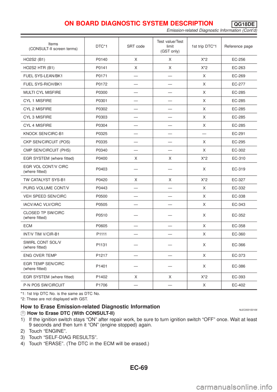
Items
(CONSULT-II screen terms)DTC*1 SRT codeTest value/Test
limit
(GST only)1st trip DTC*1 Reference page
HO2S2 (B1) P0140 X X X*2 EC-256
HO2S2 HTR (B1) P0141 X X X*2 EC-263
FUEL SYS-LEAN/BK1 P0171 Ð Ð X EC-269
FUEL SYS-RICH/BK1 P0172 Ð Ð X EC-277
MULTI CYL MISFIRE P0300 Ð Ð X EC-285
CYL 1 MISFIRE P0301 Ð Ð X EC-285
CYL 2 MISFIRE P0302 Ð Ð X EC-285
CYL 3 MISFIRE P0303 Ð Ð X EC-285
CYL 4 MISFIRE P0304 Ð Ð X EC-285
KNOCK SEN/CIRC-B1 P0325 Ð Ð Ð EC-291
CKP SEN/CIRCUIT (POS) P0335 Ð Ð X EC-295
CMP SEN/CIRCUIT (PHS) P0340 Ð Ð X EC-302
EGR SYSTEM (where fitted) P0400 X X X*2 EC-310
EGR VOL CONT/V CIRC
(where fitted)P0403 Ð Ð X EC-319
TW CATALYST SYS-B1 P0420 X X X*2 EC-327
PURG VOLUME CONT/V P0443 Ð Ð X EC-332
VEH SPEED SEN/CIRC P0500 Ð Ð X EC-338
IACV/AAC VLV/CIRC P0505 Ð Ð X EC-343
CLOSED TP SW/CIRC
(where fitted)P0510 Ð Ð X EC-352
ECM P0605 Ð Ð X EC-358
INT/V TIM V/CIR-B1 P1111 Ð Ð XEC-360
SWIRL CONT SOL/V
(where fitted)P1131 Ð Ð X EC-366
ENG OVER TEMP P1217 Ð Ð X EC-373
EGR TEMP SEN/CIRC
(where fitted)P1401 Ð Ð X EC-386
EGR SYSTEM (where fitted) P1402 X X X*2 EC-393
P-N POS SW/CIRCUIT P1706 Ð Ð X EC-402
*1: 1st trip DTC No. is the same as DTC No.
*2: These are not displayed with GST.
How to Erase Emission-related Diagnostic InformationNLEC0031S0106How to Erase DTC (With CONSULT-II)
1) If the ignition switch stays ªONº after repair work, be sure to turn ignition switch ªOFFº once. Wait at least
9 seconds and then turn it ªONº (engine stopped) again.
2) Touch ªENGINEº.
3) Touch ªSELF-DIAG RESULTSº.
4) Touch ªERASEº. (The DTC in the ECM will be erased.)
ON BOARD DIAGNOSTIC SYSTEM DESCRIPTIONQG18DE
Emission-related Diagnostic Information (Cont'd)
EC-69
Page 547 of 3051
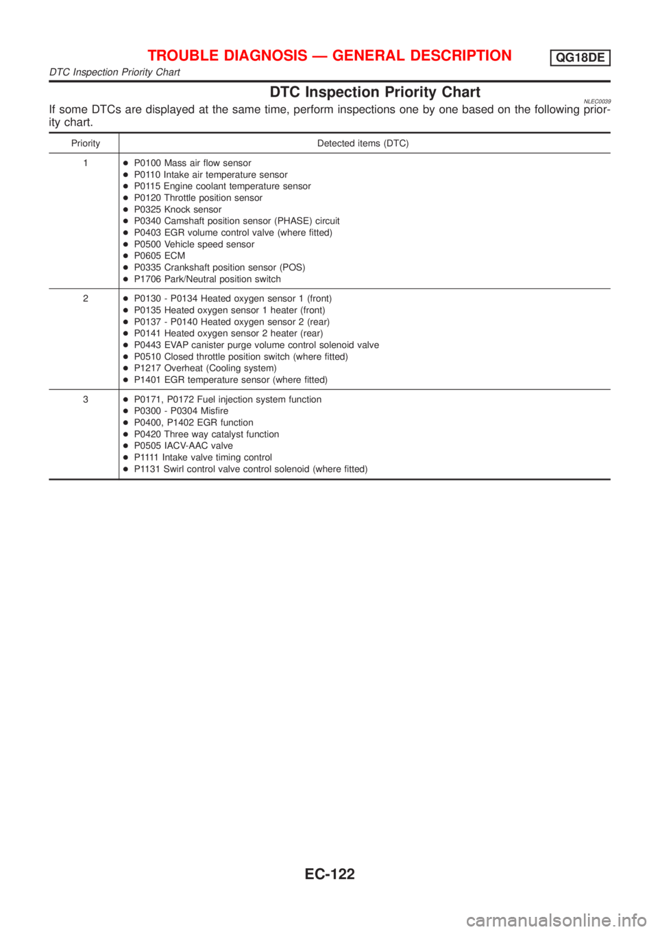
DTC Inspection Priority ChartNLEC0039If some DTCs are displayed at the same time, perform inspections one by one based on the following prior-
ity chart.
Priority Detected items (DTC)
1+P0100 Mass air flow sensor
+P0110 Intake air temperature sensor
+P0115 Engine coolant temperature sensor
+P0120 Throttle position sensor
+P0325 Knock sensor
+P0340 Camshaft position sensor (PHASE) circuit
+P0403 EGR volume control valve (where fitted)
+P0500 Vehicle speed sensor
+P0605 ECM
+P0335 Crankshaft position sensor (POS)
+P1706 Park/Neutral position switch
2+P0130 - P0134 Heated oxygen sensor 1 (front)
+P0135 Heated oxygen sensor 1 heater (front)
+P0137 - P0140 Heated oxygen sensor 2 (rear)
+P0141 Heated oxygen sensor 2 heater (rear)
+P0443 EVAP canister purge volume control solenoid valve
+P0510 Closed throttle position switch (where fitted)
+P1217 Overheat (Cooling system)
+P1401 EGR temperature sensor (where fitted)
3+P0171, P0172 Fuel injection system function
+P0300 - P0304 Misfire
+P0400, P1402 EGR function
+P0420 Three way catalyst function
+P0505 IACV-AAC valve
+P 1111Intake valve timing control
+P1131 Swirl control valve control solenoid (where fitted)
TROUBLE DIAGNOSIS Ð GENERAL DESCRIPTIONQG18DE
DTC Inspection Priority Chart
EC-122
Page 716 of 3051
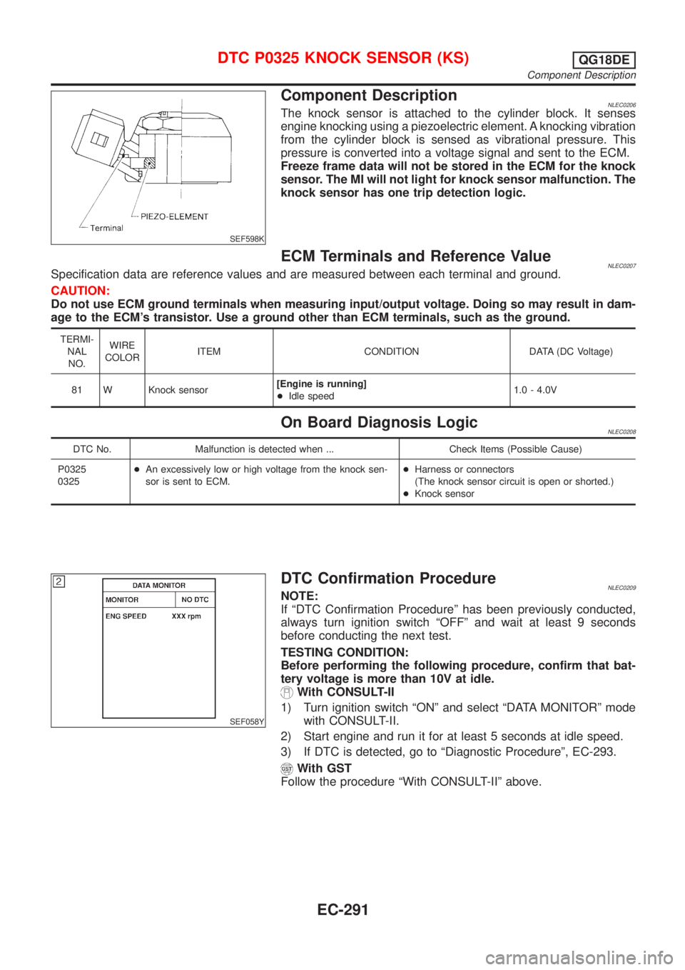
SEF598K
Component DescriptionNLEC0206The knock sensor is attached to the cylinder block. It senses
engine knocking using a piezoelectric element. A knocking vibration
from the cylinder block is sensed as vibrational pressure. This
pressure is converted into a voltage signal and sent to the ECM.
Freeze frame data will not be stored in the ECM for the knock
sensor. The MI will not light for knock sensor malfunction. The
knock sensor has one trip detection logic.
ECM Terminals and Reference ValueNLEC0207Specification data are reference values and are measured between each terminal and ground.
CAUTION:
Do not use ECM ground terminals when measuring input/output voltage. Doing so may result in dam-
age to the ECM's transistor. Use a ground other than ECM terminals, such as the ground.
TERMI-
NAL
NO.WIRE
COLORITEM CONDITION DATA (DC Voltage)
81 W Knock sensor[Engine is running]
+Idle speed1.0 - 4.0V
On Board Diagnosis LogicNLEC0208
DTC No. Malfunction is detected when ... Check Items (Possible Cause)
P0325
0325+An excessively low or high voltage from the knock sen-
sor is sent to ECM.+Harness or connectors
(The knock sensor circuit is open or shorted.)
+Knock sensor
SEF058Y
DTC Confirmation ProcedureNLEC0209NOTE:
If ªDTC Confirmation Procedureº has been previously conducted,
always turn ignition switch ªOFFº and wait at least 9 seconds
before conducting the next test.
TESTING CONDITION:
Before performing the following procedure, confirm that bat-
tery voltage is more than 10V at idle.
With CONSULT-II
1) Turn ignition switch ªONº and select ªDATA MONITORº mode
with CONSULT-II.
2) Start engine and run it for at least 5 seconds at idle speed.
3) If DTC is detected, go to ªDiagnostic Procedureº, EC-293.
With GST
Follow the procedure ªWith CONSULT-IIº above.
DTC P0325 KNOCK SENSOR (KS)QG18DE
Component Description
EC-291