2001 NISSAN ALMERA TINO length
[x] Cancel search: lengthPage 208 of 3051
SAT266K
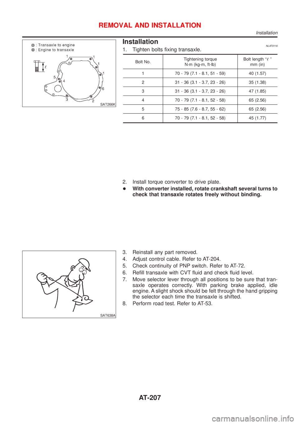
InstallationNLAT01161. Tighten bolts fixing transaxle.
Bolt No.Tightening torque
N´m (kg-m, ft-lb)Bolt length ª!º
mm (in)
1 70 - 79 (7.1 - 8.1, 51 - 59) 40 (1.57)
2 31 - 36 (3.1 - 3.7, 23 - 26) 35 (1.38)
3 31 - 36 (3.1 - 3.7, 23 - 26) 47 (1.85)
4 70 - 79 (7.1 - 8.1, 52 - 58) 65 (2.56)
5 75 - 85 (7.6 - 8.7, 55 - 62) 65 (2.56)
6 70 - 79 (7.1 - 8.1, 52 - 58) 45 (1.77)
2. Install torque converter to drive plate.
+With converter installed, rotate crankshaft several turns to
check that transaxle rotates freely without binding.
SAT638A
3. Reinstall any part removed.
4. Adjust control cable. Refer to AT-204.
5. Check continuity of PNP switch. Refer to AT-72.
6. Refill transaxle with CVT fluid and check fluid level.
7. Move selector lever through all positions to be sure that tran-
saxle operates correctly. With parking brake applied, idle
engine. A slight shock should be felt through the hand gripping
the selector each time the transaxle is shifted.
8. Perform road test. Refer to AT-53.
REMOVAL AND INSTALLATION
Installation
AT-207
Page 226 of 3051
+Use grease according to AX-19, SDS.
SFA800
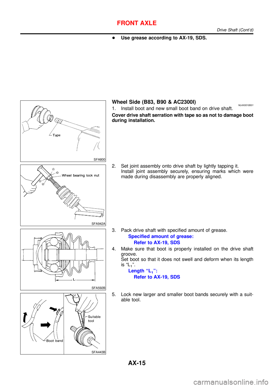
Wheel Side (B83, B90 & AC2300I)NLAX0019S011. Install boot and new small boot band on drive shaft.
Cover drive shaft serration with tape so as not to damage boot
during installation.
SFA942A
2. Set joint assembly onto drive shaft by lightly tapping it.
Install joint assembly securely, ensuring marks which were
made during disassembly are properly aligned.
SFA592B
3. Pack drive shaft with specified amount of grease.
Specified amount of grease:
Refer to AX-19, SDS
4. Make sure that boot is properly installed on the drive shaft
groove.
Set boot so that it does not swell and deform when its length
is“L
1”.
Length“L
1”:
Refer to AX-19, SDS
SFA443B
5. Lock new larger and smaller boot bands securely with a suit-
able tool.
FRONT AXLE
Drive Shaft (Cont’d)
AX-15
Page 227 of 3051
SFA313B
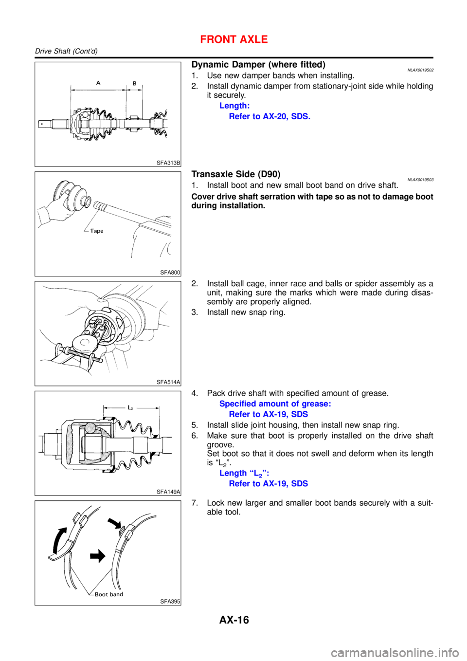
Dynamic Damper (where fitted)NLAX0019S021. Use new damper bands when installing.
2. Install dynamic damper from stationary-joint side while holding
it securely.
Length:
Refer to AX-20, SDS.
SFA800
Transaxle Side (D90)NLAX0019S031. Install boot and new small boot band on drive shaft.
Cover drive shaft serration with tape so as not to damage boot
during installation.
SFA514A
2. Install ball cage, inner race and balls or spider assembly as a
unit, making sure the marks which were made during disas-
sembly are properly aligned.
3. Install new snap ring.
SFA149A
4. Pack drive shaft with specified amount of grease.
Specified amount of grease:
Refer to AX-19, SDS
5. Install slide joint housing, then install new snap ring.
6. Make sure that boot is properly installed on the drive shaft
groove.
Set boot so that it does not swell and deform when its length
is“L
2”.
Length“L
2”:
Refer to AX-19, SDS
SFA395
7. Lock new larger and smaller boot bands securely with a suit-
able tool.
FRONT AXLE
Drive Shaft (Cont’d)
AX-16
Page 230 of 3051

Service Data and Specifications (SDS)
DRIVE SHAFT=NLAX0020
NLAX0020S02
QG SR YD
LH RH
Joint type Transaxle side T83 GI2300I D90 T86C D90
Grease Quality 39709-55E00
Joint type Wheel side B83 AC2300I Z100 B90
Grease Quality Nissan genuine grease or equivalent 39209-01A00Nissan genuine
grease or equiva-
lent
Grease
Capacity
g (oz)Transaxle side125 - 145
(4.41 - 5.11)125.5 - 135.5
(4.42 - 4.77)165 - 175
(5.82 - 6.17)145 - 155
(5.11 - 5.47)145 - 165
(5.11 - 5.82)
Wheel side80 - 100
(2.82 - 3.53)40-50
(1.41 - 1.76)Cannot be disassembled *2120 - 140
(4.41 - 4.94)
Boot length
mm (in)Transaxle side“L
2”98 - 100
(3.86 - 3.94)*197 - 99 (3.82 - 3.90)*1 98 (3.86) *1
Wheel side“L
1”94-96
(3.70 - 3.78)*1Cannot be disassembled *2 110 (4.33)
SFA961AA
SFA962A
*1: Fit boot to boot groove in bar shaft
*2: Z100 type joint assembly cannot be disassembled because a plastic boot and special boot band are used. Do not use other drive
shaft boots. If the boot or joint is damaged, replace the drive shaft assembly.
FRONT AXLE
Service Data and Specifications (SDS)
AX-19
Page 238 of 3051
BRAKE SYSTEM
SECTION
BR
CONTENTS
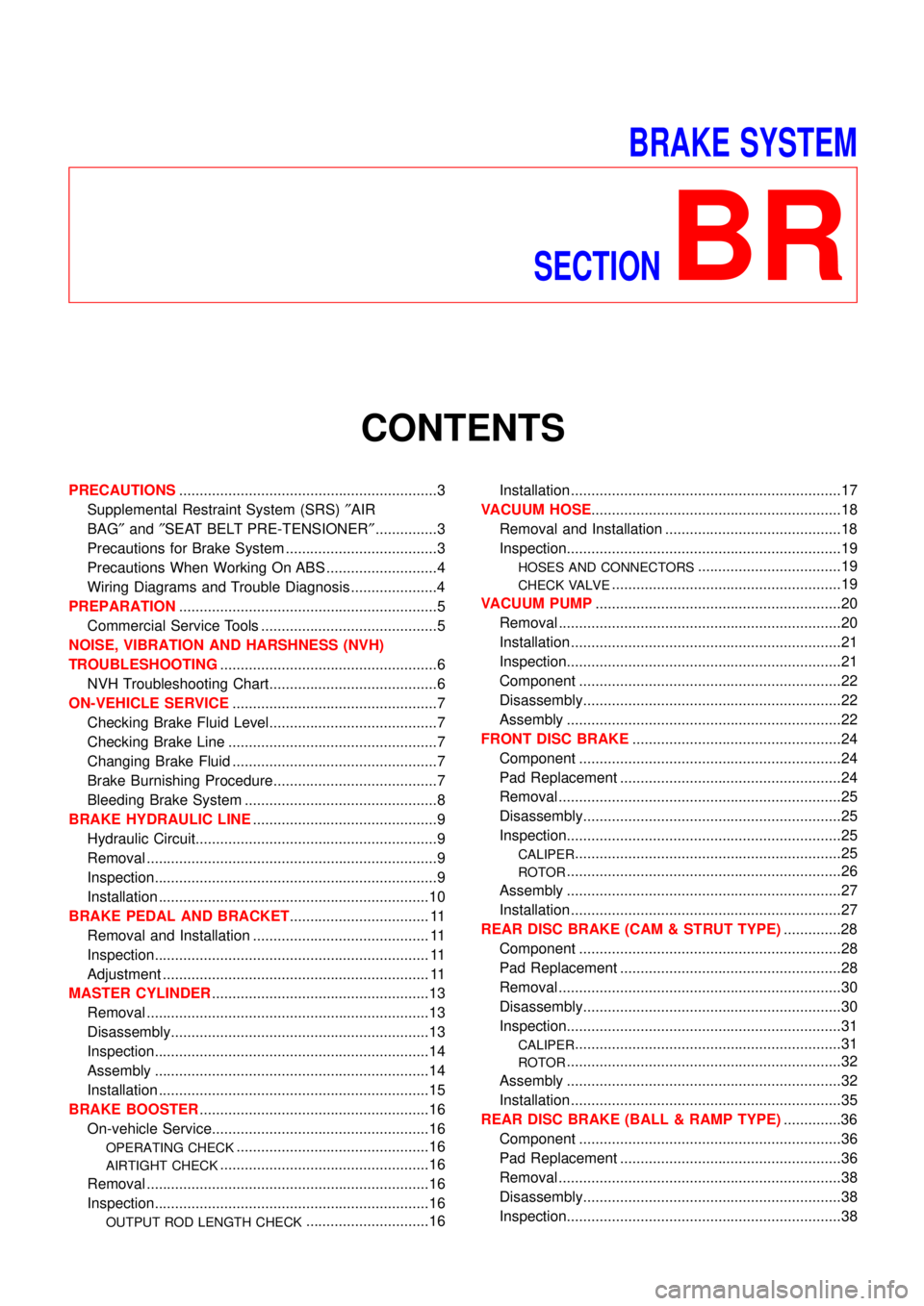
PRECAUTIONS...............................................................3
Supplemental Restraint System (SRS)″AIR
BAG″and″SEAT BELT PRE-TENSIONER″...............3
Precautions for Brake System .....................................3
Precautions When Working On ABS ...........................4
Wiring Diagrams and Trouble Diagnosis .....................4
PREPARATION...............................................................5
Commercial Service Tools ...........................................5
NOISE, VIBRATION AND HARSHNESS (NVH)
TROUBLESHOOTING.....................................................6
NVH Troubleshooting Chart.........................................6
ON-VEHICLE SERVICE..................................................7
Checking Brake Fluid Level.........................................7
Checking Brake Line ...................................................7
Changing Brake Fluid ..................................................7
Brake Burnishing Procedure........................................7
Bleeding Brake System ...............................................8
BRAKE HYDRAULIC LINE.............................................9
Hydraulic Circuit...........................................................9
Removal .......................................................................9
Inspection.....................................................................9
Installation ..................................................................10
BRAKE PEDAL AND BRACKET.................................. 11
Removal and Installation ........................................... 11
Inspection................................................................... 11
Adjustment ................................................................. 11
MASTER CYLINDER.....................................................13
Removal .....................................................................13
Disassembly...............................................................13
Inspection...................................................................14
Assembly ...................................................................14
Installation ..................................................................15
BRAKE BOOSTER........................................................16
On-vehicle Service.....................................................16
OPERATING CHECK...............................................16
AIRTIGHT CHECK...................................................16
Removal .....................................................................16
Inspection...................................................................16
OUTPUT ROD LENGTH CHECK..............................16Installation ..................................................................17
VACUUM HOSE.............................................................18
Removal and Installation ...........................................18
Inspection...................................................................19
HOSES AND CONNECTORS...................................19
CHECK VALVE........................................................19
VACUUM PUMP............................................................20
Removal .....................................................................20
Installation ..................................................................21
Inspection...................................................................21
Component ................................................................22
Disassembly...............................................................22
Assembly ...................................................................22
FRONT DISC BRAKE...................................................24
Component ................................................................24
Pad Replacement ......................................................24
Removal .....................................................................25
Disassembly...............................................................25
Inspection...................................................................25
CALIPER.................................................................25
ROTOR...................................................................26
Assembly ...................................................................27
Installation ..................................................................27
REAR DISC BRAKE (CAM & STRUT TYPE)..............28
Component ................................................................28
Pad Replacement ......................................................28
Removal .....................................................................30
Disassembly...............................................................30
Inspection...................................................................31
CALIPER.................................................................31
ROTOR...................................................................32
Assembly ...................................................................32
Installation ..................................................................35
REAR DISC BRAKE (BALL & RAMP TYPE)..............36
Component ................................................................36
Pad Replacement ......................................................36
Removal .....................................................................38
Disassembly...............................................................38
Inspection...................................................................38
Page 253 of 3051
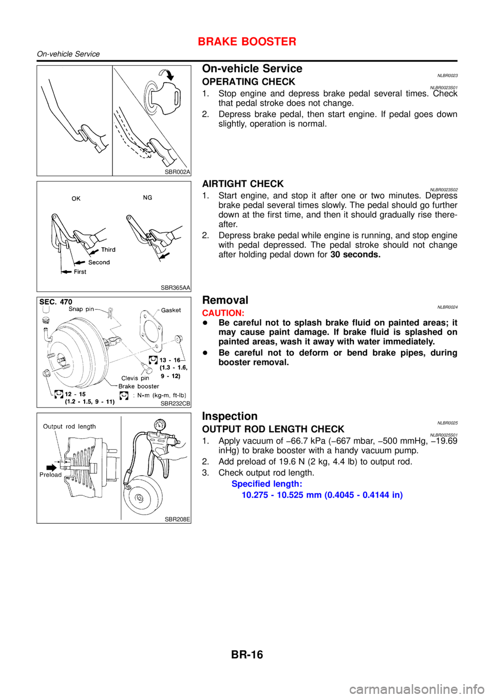
SBR002A
On-vehicle ServiceNLBR0023OPERATING CHECKNLBR0023S011. Stop engine and depress brake pedal several times. Check
that pedal stroke does not change.
2. Depress brake pedal, then start engine. If pedal goes down
slightly, operation is normal.
SBR365AA
AIRTIGHT CHECKNLBR0023S021. Start engine, and stop it after one or two minutes. Depress
brake pedal several times slowly. The pedal should go further
down at the first time, and then it should gradually rise there-
after.
2. Depress brake pedal while engine is running, and stop engine
with pedal depressed. The pedal stroke should not change
after holding pedal down for30 seconds.
SBR232CB
RemovalNLBR0024CAUTION:
+Be careful not to splash brake fluid on painted areas; it
may cause paint damage. If brake fluid is splashed on
painted areas, wash it away with water immediately.
+Be careful not to deform or bend brake pipes, during
booster removal.
SBR208E
InspectionNLBR0025OUTPUT ROD LENGTH CHECKNLBR0025S011. Apply vacuum of �66.7 kPa (�667 mbar, �500 mmHg, �19.69
inHg) to brake booster with a handy vacuum pump.
2. Add preload of 19.6 N (2 kg, 4.4 lb) to output rod.
3. Check output rod length.
Specified length:
10.275 - 10.525 mm (0.4045 - 0.4144 in)
BRAKE BOOSTER
On-vehicle Service
BR-16
Page 259 of 3051
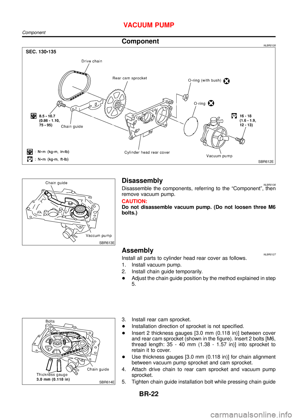
ComponentNLBR0126
SBR612E
SBR613E
DisassemblyNLBR0136Disassemble the components, referring to the“Component”, then
remove vacuum pump.
CAUTION:
Do not disassemble vacuum pump. (Do not loosen three M6
bolts.)
AssemblyNLBR0127Install all parts to cylinder head rear cover as follows.
1. Install vacuum pump.
2. Install chain guide temporarily.
+Adjust the chain guide position by the method explained in step
5.
SBR614E
3. Install rear cam sprocket.
+Installation direction of sprocket is not specified.
+Insert 2 thickness gauges [3.0 mm (0.118 in)] between cover
and rear cam sprocket (shown in the figure). Insert 2 bolts [M6,
thread length: 35 - 40 mm (1.38 - 1.57 in)] into sprocket to
retain it to cover.
+Use thickness gauges [3.0 mm (0.118 in)] for chain alignment
between vacuum pump sprocket and cam sprocket.
4. Attach drive chain to rear cam sprocket and vacuum pump
sprocket.
5. Tighten chain guide installation bolt while pressing chain guide
VACUUM PUMP
Component
BR-22
Page 330 of 3051

General SpecificationsNLBR0077Unit: mm (in)
EngineQG18DE, SR20DE YD22DDTi
Front BrakeBrake model CL25VCG
Cylinder bore diameter 57.2 (2.2529)
Pad
Length×width×thickness110.6×54.2×11.0 (4.35×2.13×0.433)
Rotor outer
diameter×thickness280×28 (11.02×1.10)
Rear BrakeBrake model CL11HDG (disc brake)
Cylinder bore diam-
eterCam & Strut type 38 (1.496)
Ball & Ramp type 38.2 (1.504)
Pad
Length×width×thickness79.8×38.5×9.3 (3.142×1.516×0.37)
Rotor outer diameter×thickness 278×10 (10.94×0.39)
Master cylinder Cylinder bore diameter 23.81 (15/16)
Brake boosterBooster model S255 M215T S255
DiaphragmPrimary 255 (10.04) 230 (9.06) 255 (10.04)
Secondary—205 (8.07)—
Specified brake fluidDOT 4
Disc BrakeNLBR0078Unit: mm (in)
Brake modelCL25VCG CL11HDG
Pad wear limit Minimum thickness 2.0 (0.078) 2.0 (0.079)
Rotor repair limitMaximum runout 0.07 (0.0028) 0.07 (0.0028)
Minimum thickness 26.0 (1.024) 9 (0.35)
Brake PedalNLBR0079Unit: mm (in)
Free height“H”*LHDM/T 154.8 - 164.8 (6.09 - 6.49)
CVT 164 - 174 (6.46 - 6.85)
RHDM/T 154.8 - 164.8 (6.09 - 6.49)
CVT 164 - 174 (6.46 - 6.85)
Clearance“C”between pedal stopper and threaded end of stop lamp switch or brake switch 0.75 - 2.00 (0.0295 - 0.0787)
*: Measured from surface of dash panel to surface of pedal pad
Parking BrakeNLBR0080
TypeCenter lever
Number of notches
[under force of 196 N (20 kg, 44 lb)]5-6
Number of notches
when warning lamp switch comes on1
SERVICE DATA AND SPECIFICATIONS (SDS)
General Specifications
BR-93