Page 2322 of 3051
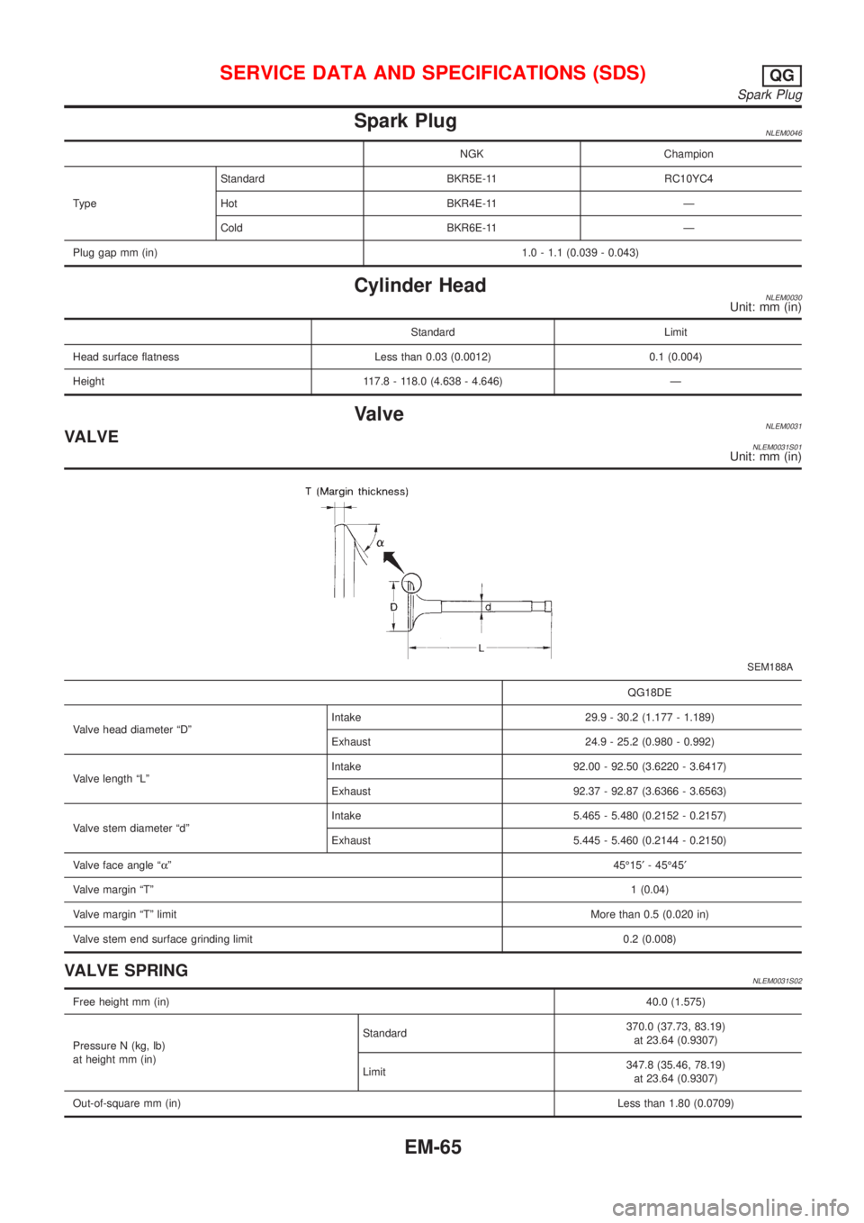
Spark PlugNLEM0046
NGK Champion
TypeStandard BKR5E-11 RC10YC4
Hot BKR4E-11 Ð
Cold BKR6E-11 Ð
Plug gap mm (in)1.0 - 1.1 (0.039 - 0.043)
Cylinder HeadNLEM0030Unit: mm (in)
Standard Limit
Head surface flatness Less than 0.03 (0.0012) 0.1 (0.004)
Height 117.8 - 118.0 (4.638 - 4.646) Ð
ValveNLEM0031VALVENLEM0031S01Unit: mm (in)
SEM188A
QG18DE
Valve head diameter ªDºIntake 29.9 - 30.2 (1.177 - 1.189)
Exhaust 24.9 - 25.2 (0.980 - 0.992)
Valve length ªLºIntake 92.00 - 92.50 (3.6220 - 3.6417)
Exhaust 92.37 - 92.87 (3.6366 - 3.6563)
Valve stem diameter ªdºIntake 5.465 - 5.480 (0.2152 - 0.2157)
Exhaust 5.445 - 5.460 (0.2144 - 0.2150)
Valve face angle ªaº45É15¢- 45É45¢
Valve margin ªTº1 (0.04)
Valve margin ªTº limitMore than 0.5 (0.020 in)
Valve stem end surface grinding limit0.2 (0.008)
VALVE SPRINGNLEM0031S02
Free height mm (in)40.0 (1.575)
Pressure N (kg, lb)
at height mm (in)Standard370.0 (37.73, 83.19)
at 23.64 (0.9307)
Limit347.8 (35.46, 78.19)
at 23.64 (0.9307)
Out-of-square mm (in)Less than 1.80 (0.0709)
SERVICE DATA AND SPECIFICATIONS (SDS)QG
Spark Plug
EM-65
Page 2324 of 3051
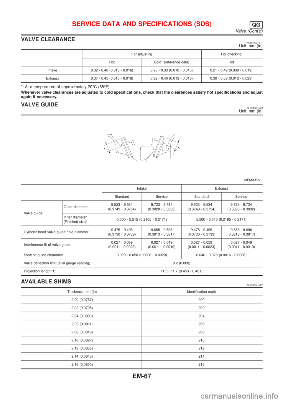
VALVE CLEARANCE=NLEM0031S11Unit: mm (in)
For adjusting For checking
Hot Cold* (reference data) Hot
Intake 0.32 - 0.40 (0.013 - 0.016) 0.25 - 0.33 (0.010 - 0.013) 0.21 - 0.49 (0.008 - 0.019)
Exhaust 0.37 - 0.45 (0.015 - 0.018) 0.32 - 0.40 (0.013 - 0.016) 0.30 - 0.58 (0.012 - 0.023)
*: At a temperature of approximately 20ÉC (68ÉF)
Whenever valve clearances are adjusted to cold specifications, check that the clearances satisfy hot specifications and adjust
again if necessary.
VALVE GUIDENLEM0031S04Unit: mm (in)
MEM096A
Intake Exhaust
Standard Service Standard Service
Valve guideOuter diameter9.523 - 9.534
(0.3749 - 0.3754)9.723 - 9.734
(0.3828 - 0.3832)9.523 - 9.534
(0.3749 - 0.3754)9.723 - 9.734
(0.3828 - 0.3832)
Inner diameter
[Finished size]5.500 - 5.515 (0.2165 - 0.2171) 5.500 - 5.515 (0.2165 - 0.2171)
Cylinder head valve guide hole diameter9.475 - 9.496
(0.3730 - 0.3739)9.685 - 9.696
(0.3813 - 0.3817)9.475 - 9.496
(0.3730 - 0.3739)9.685 - 9.696
(0.3813 - 0.3817)
Interference fit of valve guide0.027 - 0.059
(0.0011 - 0.0023)0.027 - 0.049
(0.0011 - 0.0019)0.027 - 0.059
(0.0011 - 0.0023)0.027 - 0.049
(0.0011 - 0.0019)
Stem to guide clearance 0.020 - 0.050 (0.0008 - 0.0020) 0.040 - 0.070 (0.0016 - 0.0028)
Valve deflection limit (Dial gauge reading) 0.2 (0.008)
Projection length ªLº 11.5 - 11.7 (0.453 - 0.461)
AVAILABLE SHIMSNLEM0031S07
Thickness mm (in) Identification mark
2.00 (0.0787) 200
2.02 (0.0795) 202
2.04 (0.0803) 204
2.06 (0.0811) 206
2.08 (0.0819) 208
2.10 (0.0827) 210
2.12 (0.0835) 212
2.14 (0.0843) 214
2.16 (0.0850) 216
SERVICE DATA AND SPECIFICATIONS (SDS)QG
Valve (Cont'd)
EM-67
Page 2383 of 3051
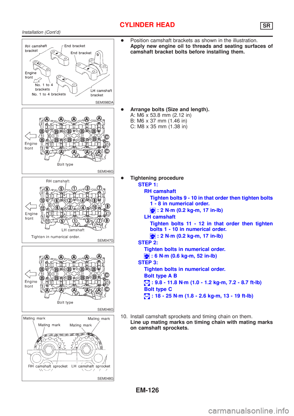
SEM098DA
+Position camshaft brackets as shown in the illustration.
Apply new engine oil to threads and seating surfaces of
camshaft bracket bolts before installing them.
SEM046G
+Arrange bolts (Size and length).
A: M6 x 53.8 mm (2.12 in)
B: M6 x 37 mm (1.46 in)
C: M8 x 35 mm (1.38 in)
SEM047G
SEM046G
+Tightening procedure
STEP 1:
RH camshaft
Tighten bolts9-10inthat order then tighten bolts
1-8innumerical order.
: 2 N´m (0.2 kg-m, 17 in-lb)
LH camshaft
Tighten bolts 11 - 12 in that order then tighten
bolts1-10innumerical order.
: 2 N´m (0.2 kg-m, 17 in-lb)
STEP 2:
Tighten bolts in numerical order.
: 6 N´m (0.6 kg-m, 52 in-lb)
STEP 3:
Tighten bolts in numerical order.
Bolt type A B
: 9.8 - 11.8 N´m (1.0 - 1.2 kg-m, 7.2 - 8.7 ft-lb)
Bolt type C
: 18 - 25 N´m (1.8 - 2.6 kg-m, 13 - 19 ft-lb)
SEM048G
10. Install camshaft sprockets and timing chain on them.
Line up mating marks on timing chain with mating marks
on camshaft sprockets.
CYLINDER HEADSR
Installation (Cont'd)
EM-126
Page 2393 of 3051
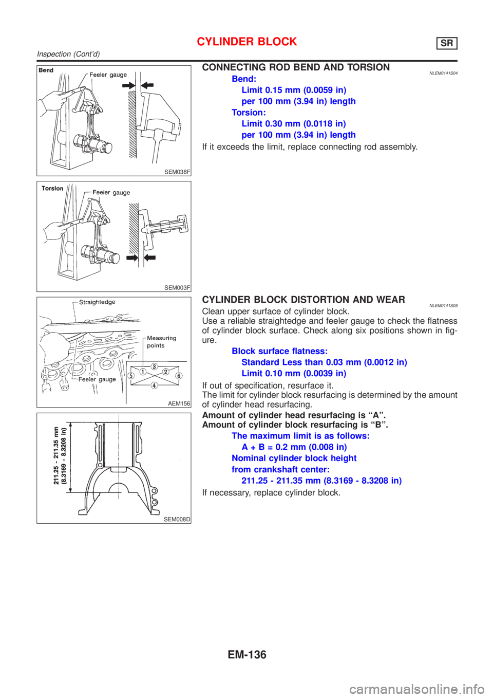
SEM038F
SEM003F
CONNECTING ROD BEND AND TORSIONNLEM0141S04Bend:
Limit 0.15 mm (0.0059 in)
per 100 mm (3.94 in) length
Torsion:
Limit 0.30 mm (0.0118 in)
per 100 mm (3.94 in) length
If it exceeds the limit, replace connecting rod assembly.
AEM156
CYLINDER BLOCK DISTORTION AND WEARNLEM0141S05Clean upper surface of cylinder block.
Use a reliable straightedge and feeler gauge to check the flatness
of cylinder block surface. Check along six positions shown in fig-
ure.
Block surface flatness:
Standard Less than 0.03 mm (0.0012 in)
Limit 0.10 mm (0.0039 in)
If out of specification, resurface it.
The limit for cylinder block resurfacing is determined by the amount
of cylinder head resurfacing.
SEM008D
Amount of cylinder head resurfacing is ªAº.
Amount of cylinder block resurfacing is ªBº.
The maximum limit is as follows:
A + B = 0.2 mm (0.008 in)
Nominal cylinder block height
from crankshaft center:
211.25 - 211.35 mm (8.3169 - 8.3208 in)
If necessary, replace cylinder block.
CYLINDER BLOCKSR
Inspection (Cont'd)
EM-136
Page 2404 of 3051
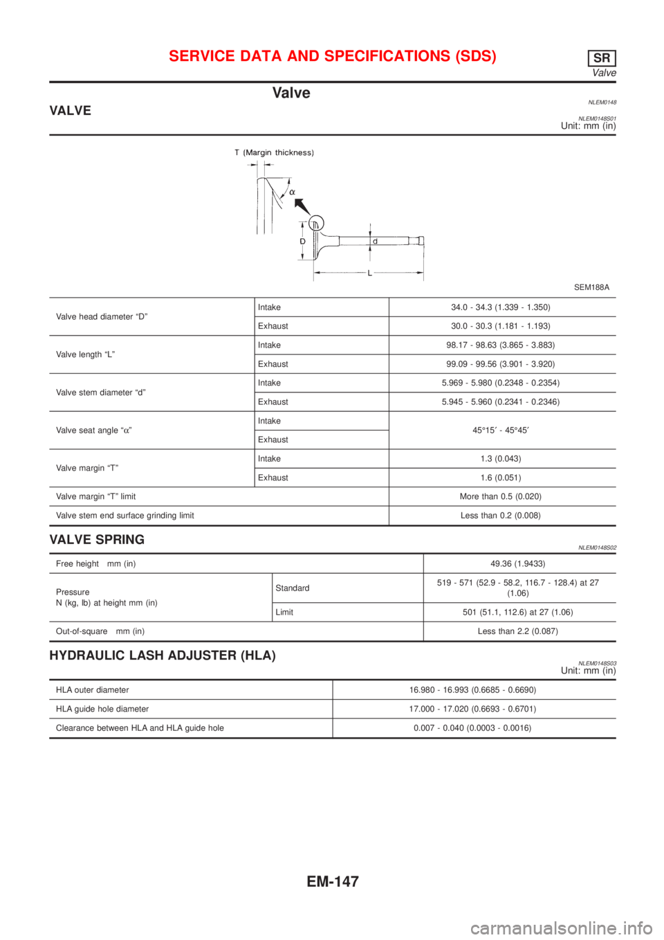
ValveNLEM0148VALVENLEM0148S01Unit: mm (in)
SEM188A
Valve head diameter ªDºIntake 34.0 - 34.3 (1.339 - 1.350)
Exhaust 30.0 - 30.3 (1.181 - 1.193)
Valve length ªLºIntake 98.17 - 98.63 (3.865 - 3.883)
Exhaust 99.09 - 99.56 (3.901 - 3.920)
Valve stem diameter ªdºIntake 5.969 - 5.980 (0.2348 - 0.2354)
Exhaust 5.945 - 5.960 (0.2341 - 0.2346)
Valve seat angle ªaºIntake
45É15¢- 45É45¢
Exhaust
Valve margin ªTºIntake 1.3 (0.043)
Exhaust 1.6 (0.051)
Valve margin ªTº limitMore than 0.5 (0.020)
Valve stem end surface grinding limit Less than 0.2 (0.008)
VALVE SPRINGNLEM0148S02
Free height mm (in)49.36 (1.9433)
Pressure
N (kg, lb) at height mm (in)Standard519 - 571 (52.9 - 58.2, 116.7 - 128.4) at 27
(1.06)
Limit 501 (51.1, 112.6) at 27 (1.06)
Out-of-square mm (in)Less than 2.2 (0.087)
HYDRAULIC LASH ADJUSTER (HLA)NLEM0148S03Unit: mm (in)
HLA outer diameter16.980 - 16.993 (0.6685 - 0.6690)
HLA guide hole diameter 17.000 - 17.020 (0.6693 - 0.6701)
Clearance between HLA and HLA guide hole 0.007 - 0.040 (0.0003 - 0.0016)
SERVICE DATA AND SPECIFICATIONS (SDS)SR
Valve
EM-147
Page 2405 of 3051
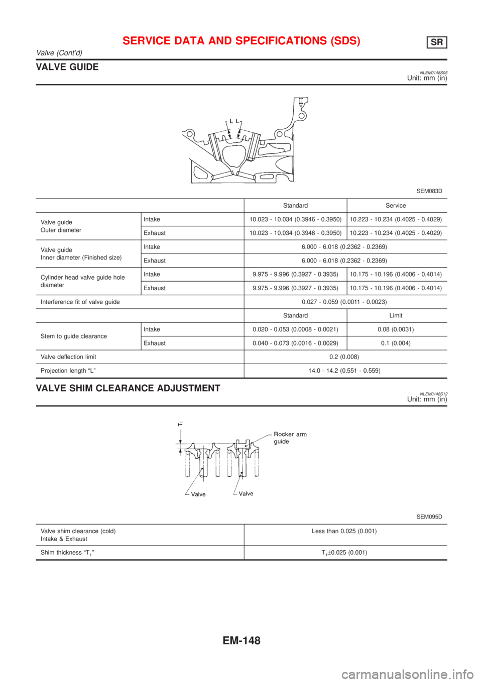
VALVE GUIDENLEM0148S05Unit: mm (in)
SEM083D
Standard Service
Valve guide
Outer diameterIntake 10.023 - 10.034 (0.3946 - 0.3950) 10.223 - 10.234 (0.4025 - 0.4029)
Exhaust 10.023 - 10.034 (0.3946 - 0.3950) 10.223 - 10.234 (0.4025 - 0.4029)
Valve guide
Inner diameter (Finished size)Intake 6.000 - 6.018 (0.2362 - 0.2369)
Exhaust 6.000 - 6.018 (0.2362 - 0.2369)
Cylinder head valve guide hole
diameterIntake 9.975 - 9.996 (0.3927 - 0.3935) 10.175 - 10.196 (0.4006 - 0.4014)
Exhaust 9.975 - 9.996 (0.3927 - 0.3935) 10.175 - 10.196 (0.4006 - 0.4014)
Interference fit of valve guide 0.027 - 0.059 (0.0011 - 0.0023)
Standard Limit
Stem to guide clearanceIntake 0.020 - 0.053 (0.0008 - 0.0021) 0.08 (0.0031)
Exhaust 0.040 - 0.073 (0.0016 - 0.0029) 0.1 (0.004)
Valve deflection limit0.2 (0.008)
Projection length ªLº14.0 - 14.2 (0.551 - 0.559)
VALVE SHIM CLEARANCE ADJUSTMENTNLEM0148S12Unit: mm (in)
SEM095D
Valve shim clearance (cold)
Intake & ExhaustLess than 0.025 (0.001)
Shim thickness ªT
1ºT1±0.025 (0.001)
SERVICE DATA AND SPECIFICATIONS (SDS)SR
Valve (Cont'd)
EM-148
Page 2430 of 3051
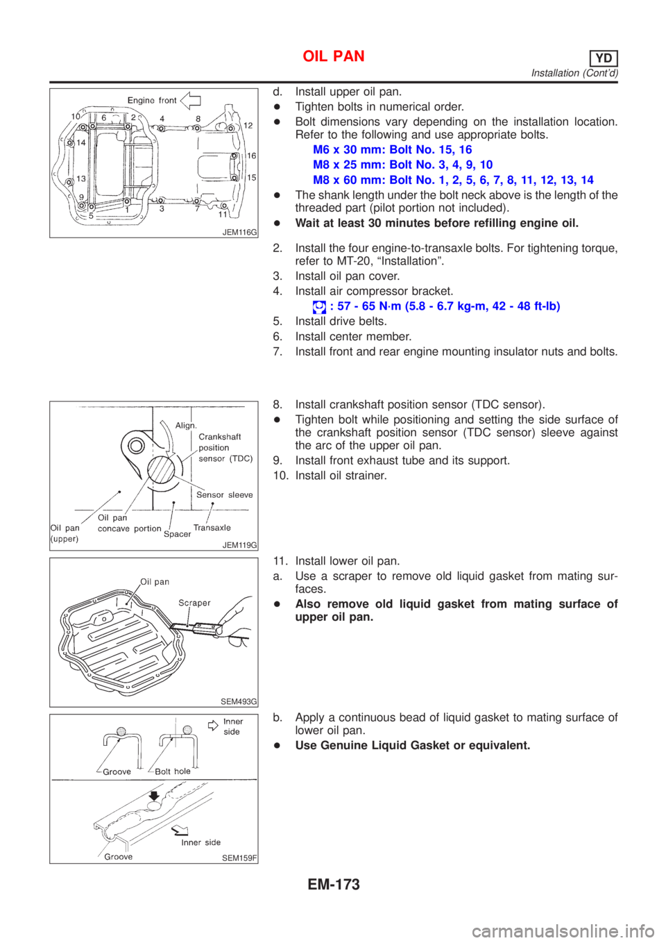
JEM116G
d. Install upper oil pan.
+Tighten bolts in numerical order.
+Bolt dimensions vary depending on the installation location.
Refer to the following and use appropriate bolts.
M6 x 30 mm: Bolt No. 15, 16
M8 x 25 mm: Bolt No. 3, 4, 9, 10
M8 x 60 mm: Bolt No. 1, 2, 5, 6, 7, 8, 11, 12, 13, 14
+The shank length under the bolt neck above is the length of the
threaded part (pilot portion not included).
+Wait at least 30 minutes before refilling engine oil.
2. Install the four engine-to-transaxle bolts. For tightening torque,
refer to MT-20, ªInstallationº.
3. Install oil pan cover.
4. Install air compressor bracket.
: 57 - 65 N´m (5.8 - 6.7 kg-m, 42 - 48 ft-lb)
5. Install drive belts.
6. Install center member.
7. Install front and rear engine mounting insulator nuts and bolts.
JEM119G
8. Install crankshaft position sensor (TDC sensor).
+Tighten bolt while positioning and setting the side surface of
the crankshaft position sensor (TDC sensor) sleeve against
the arc of the upper oil pan.
9. Install front exhaust tube and its support.
10. Install oil strainer.
SEM493G
11. Install lower oil pan.
a. Use a scraper to remove old liquid gasket from mating sur-
faces.
+Also remove old liquid gasket from mating surface of
upper oil pan.
SEM159F
b. Apply a continuous bead of liquid gasket to mating surface of
lower oil pan.
+Use Genuine Liquid Gasket or equivalent.
OIL PANYD
Installation (Cont'd)
EM-173
Page 2441 of 3051
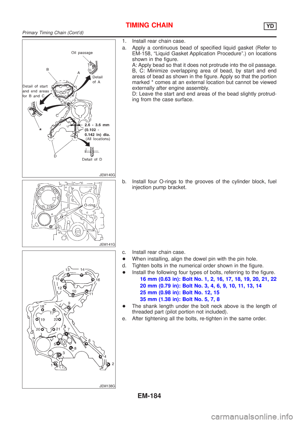
JEM140G
1. Install rear chain case.
a. Apply a continuous bead of specified liquid gasket (Refer to
EM-158, ªLiquid Gasket Application Procedureº.) on locations
shown in the figure.
A: Apply bead so that it does not protrude into the oil passage.
B, C: Minimize overlapping area of bead, by start and end
areas of bead as shown in the figure. Apply so that the portion
marked * comes at an external location but cannot be viewed
externally after engine assembly.
D: Leave the start and end areas of the bead slightly protrud-
ing from the case surface.
JEM141G
b. Install four O-rings to the grooves of the cylinder block, fuel
injection pump bracket.
JEM138G
c. Install rear chain case.
+When installing, align the dowel pin with the pin hole.
d. Tighten bolts in the numerical order shown in the figure.
+Install the following four types of bolts, referring to the figure.
16 mm (0.63 in): Bolt No. 1, 2, 16, 17, 18, 19, 20, 21, 22
20 mm (0.79 in): Bolt No. 3, 4, 6, 9, 10, 11, 13, 14
25 mm (0.98 in): Bolt No. 12, 15
35 mm (1.38 in): Bolt No. 5, 7, 8
+The shank length under the bolt neck above is the length of
threaded part (pilot portion not included).
e. After tightening all the bolts, re-tighten in the same order.
TIMING CHAINYD
Primary Timing Chain (Cont'd)
EM-184