2001 NISSAN ALMERA TINO key battery
[x] Cancel search: key batteryPage 60 of 3051
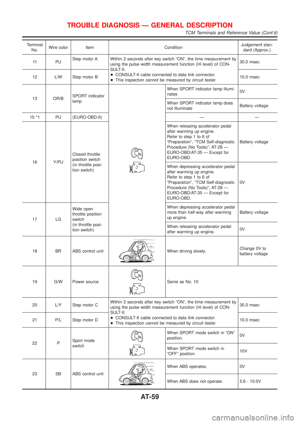
Terminal
No.Wire color Item ConditionJudgement stan-
dard (Approx.)
11 P UStep motor A Within 2 seconds after key switch ªONº, the time measurement by
using the pulse width measurement function (Hi level) of CON-
SULT-II.
+CONSULT-II cable connected to data link connector.
+This inspection cannot be measured by circuit tester.30.0 msec
12 L/W Step motor B10.0 msec
13 OR/BSPORT indicator
lamp
When SPORT indicator lamp illumi-
nates0V
When SPORT indicator lamp does
not illuminateBattery voltage
15 *1 PU (EURO-OBD-II) Ð Ð
16 Y/PUClosed throttle
position switch
(in throttle posi-
tion switch)When releasing accelerator pedal
after warming up engine.
Refer to step 1 to 6 of
ªPreparationº, ªTCM Self-diagnostic
Procedure (No Tools)º, AT-28 Ð
EURO-OBD/AT-35 Ð Except for
EURO-OBD.Battery voltage
When depressing accelerator pedal
after warming up engine.
Refer to step 1 to 6 of
ªPreparationº, ªTCM Self-diagnostic
Procedure (No Tools)º, AT-28 Ð
EURO-OBD/AT-35 Ð Except for
EURO-OBD.0V
17 LGWide open
throttle position
switch
(in throttle posi-
tion switch)When depressing accelerator pedal
more than half-way after warming
up engine.Battery voltage
When releasing accelerator pedal
after warming up engine.0V
18 BR ABS control unit
When driving slowly.Change 0V to
battery voltage
19 G/W Power source
Same as No. 10
20 L/Y Step motor CWithin 2 seconds after key switch ªONº, the time measurement by
using the pulse width measurement function (Hi level) of CON-
SULT-II.
+CONSULT-II cable connected to data link connector.
+This inspection cannot be measured by circuit tester.30.0 msec
21 P/L Step motor D10.0 msec
22 PSport mode
switch
When SPORT mode switch in ªONº
position.0V
When SPORT mode switch in
ªOFFº position.10V
23 SB ABS control unit
When ABS operates. 0V
When ABS does not operate. 5.6 - 10.0V
TROUBLE DIAGNOSIS Ð GENERAL DESCRIPTION
TCM Terminals and Reference Value (Cont'd)
AT-59
Page 199 of 3051
Diagnostic ProcedureNLAT0319SYMPTOM 1:
+Selector lever cannot be moved from ªPº position with key
in ON position and brake pedal applied.
+Selector lever can be moved from ªPº position with key in
ON position and brake pedal released.
+Selector lever can be moved from ªPº position when key
is removed from key cylinder.
SYMPTOM 2:
Ignition key cannot be removed when selector lever is set to
ªPº position. It can be removed when selector lever is set to
any position except ªPº.
1 CHECK KEY INTERLOCK CABLE
Check key interlock cable for damage.
OK or NG
OK©GO TO 2.
NG©Repair key interlock cable. Refer to AT-202.
2 CHECK SELECTOR LEVER POSITION
Check selector lever position for damage.
OK or NG
OK©GO TO 3.
NG©Check selector lever. Refer to ªON-VEHICLE SERVICE Ð PNP Switch and Control
Cable Adjustmentº, AT-204.
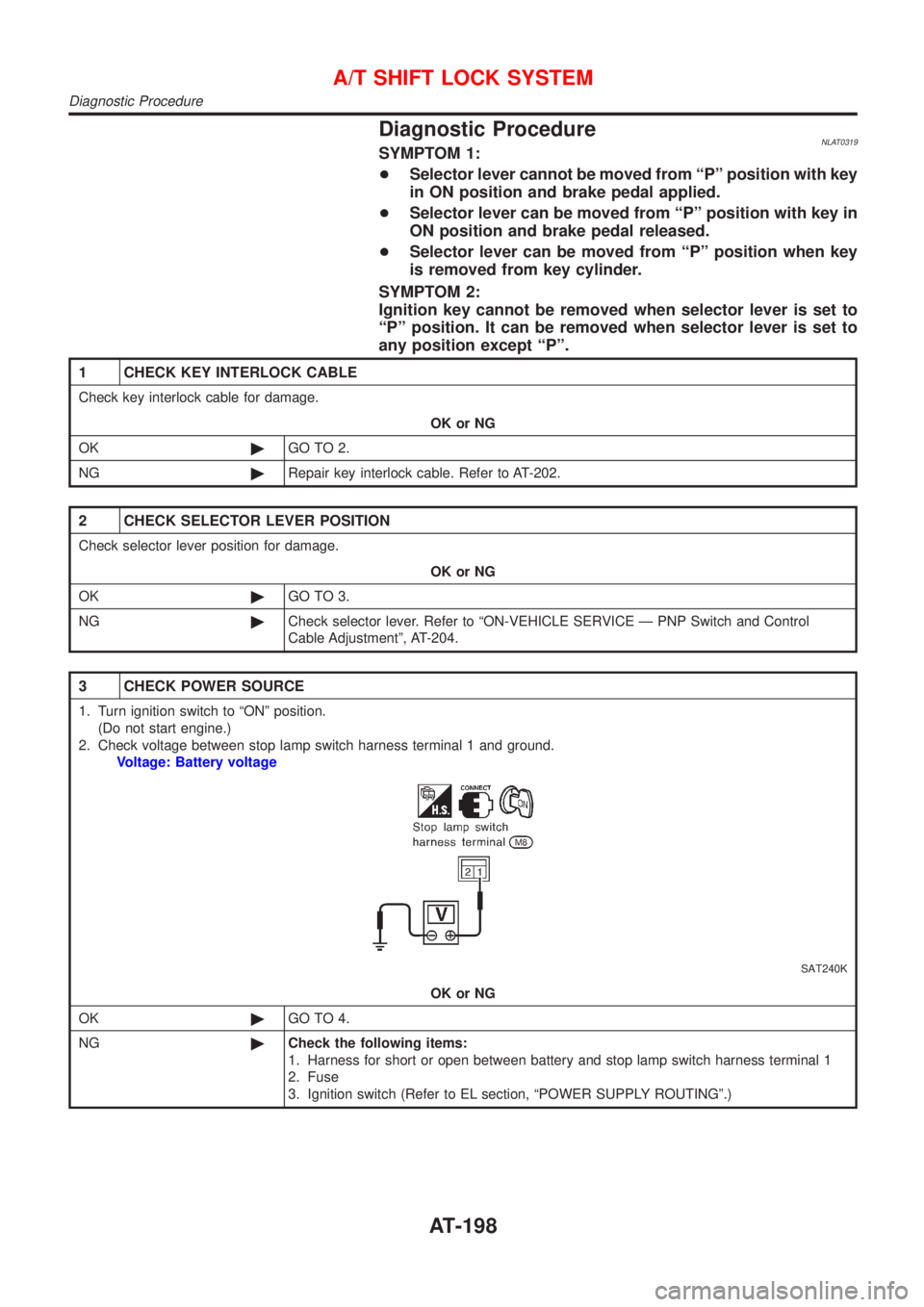
3 CHECK POWER SOURCE
1. Turn ignition switch to ªONº position.
(Do not start engine.)
2. Check voltage between stop lamp switch harness terminal 1 and ground.
Voltage: Battery voltage
SAT240K
OK or NG
OK©GO TO 4.
NG©Check the following items:
1. Harness for short or open between battery and stop lamp switch harness terminal 1
2. Fuse
3. Ignition switch (Refer to EL section, ªPOWER SUPPLY ROUTINGº.)
A/T SHIFT LOCK SYSTEM
Diagnostic Procedure
AT-198
Page 1940 of 3051
carried out. Subsequently, when the repaired audio unit is delivered to the final user again, it will be in the
ªNEWº state as to enable re-linking the audio unit to the vehicle's immobiliser system. As a result of the above,
repair of the audio unit can only be done by an authorized Clarion representative.
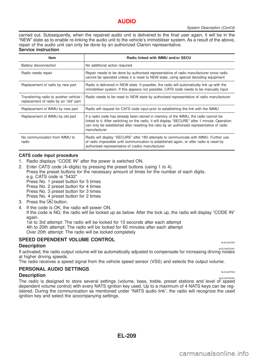
Service instruction
Item Radio linked with IMMU and/or SECU
Battery disconnection No additional action required
Radio needs repair Repair needs to be done by authorised representative of radio manufacturer since radio
cannot be operated unless it is reset to NEW state, using special decoding equipment
Replacement of radio by new part Radio is delivered in NEW state. If possible, the radio will automatically link up with the
immobiliser system. If this appears not possible, CATS code needs to be manually input
Transferring radio to another vehicle /
replacement of radio by an ªoldº partRadio needs to be reset to NEW state by authorised representative of radio manufacturer
Replacement of IMMU by new part Radio will request for CATS code input prior to establishing the link with the IMMU
Replacement of IMMU by old part If a radio code has already been stored in memory of the IMMU, the radio cannot be
linked to it. After switching on the radio, it will display ªSECUREº after 1 minute. Operation
can only be established after resetting the ratio by an authorised representative of radio
manufacturer
No communication from IMMU to
radioRadio will display ªSECUREº after 180 attempts to communicate with IMMU. Further use
of radio impossible until communication is established again, or after radio is reset by
authorised representative of (radio) manufacturer
CATS code input procedure
1. Radio displays ªCODE INº after the power is switched ON.
2. Enter CATS code (4±digits) by pressing the preset buttons (using 1 to 4).
Press the preset buttons for the necessary amount of times for the number of each digits.
e.g. CATS code is ª5432º
Press No. 1 preset button for 5 times
Press No. 2 preset button for 4 times
Press No. 3 preset button for 3 times
Press No. 4 preset button for 2 times
3. Press the
button.
4. If the code is OK, the radio will power ON.
If the code is NG, the radio will be locked up as below. After the lock up, the radio will display ªCODE INº
again.
1st to 3rd attempt: The radio will be locked for 10 seconds after each attempt
4th to 20th attempt: The radio will be locked for 60 minutes after each attempt
Over 20th attempt: The radio will be locked completely
SPEED DEPENDENT VOLUME CONTROLNLEL0497S02DescriptionNLEL0497S0201If activated, the radio output volume will be automatically adjusted to compensate for increasing driving noises
at higher driving speeds.
The radio receives a speed signal from the vehicle speed sensor (VSS) and selects the output volume.
PERSONAL AUDIO SETTINGSNLEL0497S03DescriptionNLEL0497S0301The radio is designed to store several settings (volume, bass, treble, preset stations and level of speed
dependent volume control) with every NATS ignition key used. Up to a maximum of 4 NATS keys can be reg-
istered. During the communication as mentioned under ªNATS audio linkº, the radio will recognize the used
ignition key and select the accompanying settings.
AUDIO
System Description (Cont'd)
EL-209
Page 2013 of 3051

knob, key or multi-remote controller to ªLOCKº locks the door once but then immediately unlocks all doors.
(signal from door unlock sensor driver side)
System initialization
+System initialization is required when battery cables are reconnected. Conduct the following to release
super lock once;
Ð insert the key into the ignition key cylinder and turn it to ON.
Ð LOCK/UNLOCK operation using door key cylinder or multi-remote controller.
POWER DOOR LOCK Ð SUPER LOCK Ð
System Description/RHD Models (Cont'd)
EL-282
Page 2044 of 3051
IGNITION SWITCH ªONº CIRCUIT CHECKNLEL0477S11
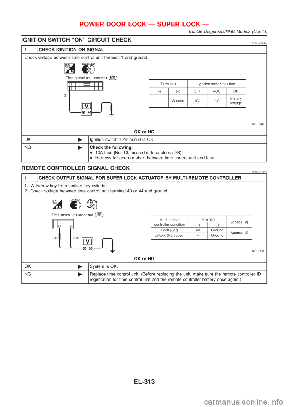
1 CHECK IGNITION ON SIGNAL
Check voltage between time control unit terminal 1 and ground.
NEL646
OK or NG
OK©Ignition switch ªONº circuit is OK.
NG©Check the following.
+10A fuse [No. 10, located in fuse block (J/B)]
+Harness for open or short between time control unit and fuse
REMOTE CONTROLLER SIGNAL CHECKNLEL0477S12
1 CHECK OUTPUT SIGNAL FOR SUPER LOCK ACTUATOR BY MULTI-REMOTE CONTROLLER
1. Withdraw key from ignition key cylinder.
2. Check voltage between time control unit terminal 40 or 44 and ground.
NEL693
OK or NG
OK©System is OK.
NG©Replace time control unit. (Before replacing the unit, make sure the remote controller ID
registration for time control unit and the remote controller battery once again.)
POWER DOOR LOCK Ð SUPER LOCK Ð
Trouble Diagnoses/RHD Models (Cont'd)
EL-313
Page 2057 of 3051
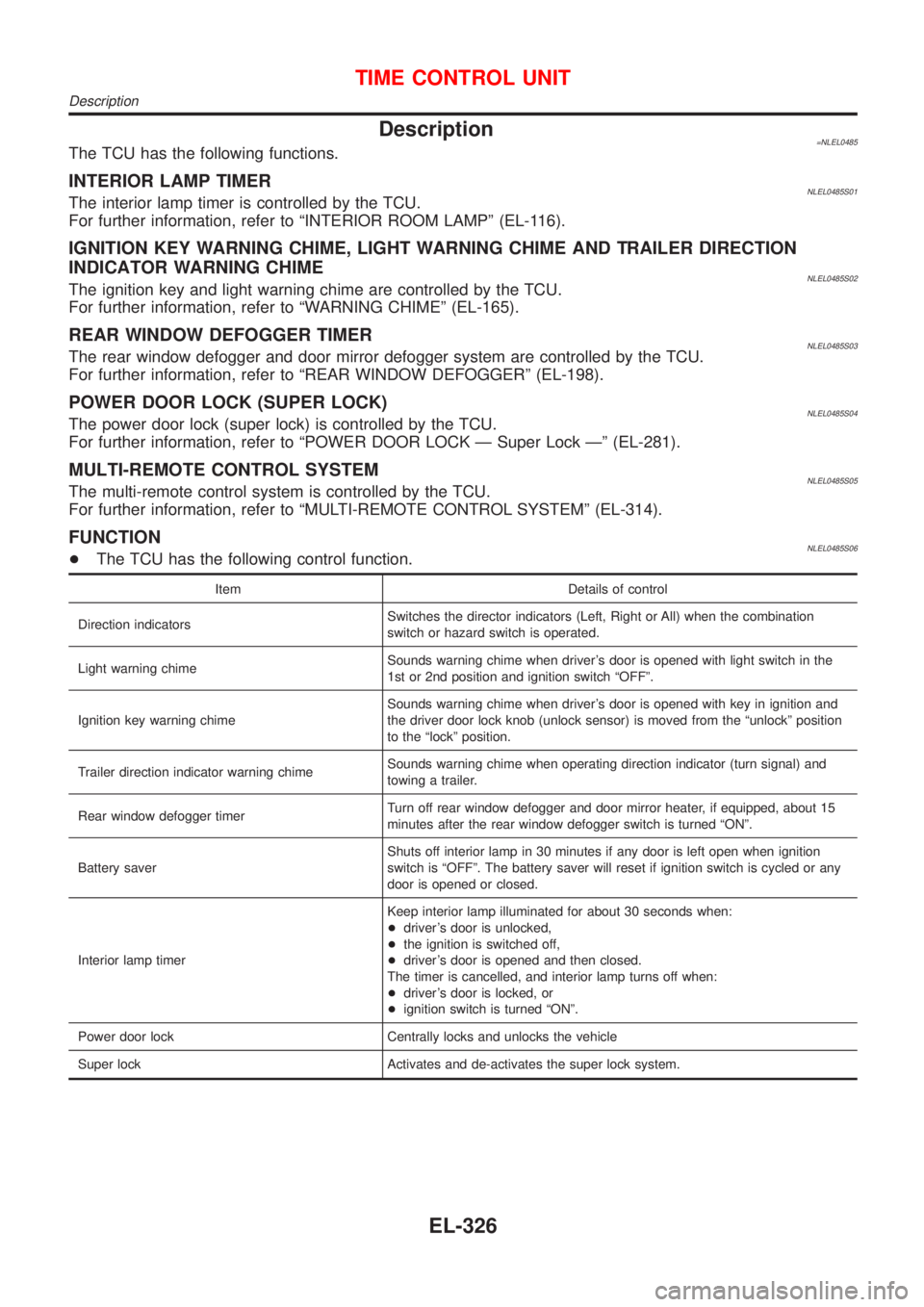
Description=NLEL0485The TCU has the following functions.
INTERIOR LAMP TIMERNLEL0485S01The interior lamp timer is controlled by the TCU.
For further information, refer to ªINTERIOR ROOM LAMPº (EL-116).
IGNITION KEY WARNING CHIME, LIGHT WARNING CHIME AND TRAILER DIRECTION
INDICATOR WARNING CHIME
NLEL0485S02The ignition key and light warning chime are controlled by the TCU.
For further information, refer to ªWARNING CHIMEº (EL-165).
REAR WINDOW DEFOGGER TIMERNLEL0485S03The rear window defogger and door mirror defogger system are controlled by the TCU.
For further information, refer to ªREAR WINDOW DEFOGGERº (EL-198).
POWER DOOR LOCK (SUPER LOCK)NLEL0485S04The power door lock (super lock) is controlled by the TCU.
For further information, refer to ªPOWER DOOR LOCK Ð Super Lock к (EL-281).
MULTI-REMOTE CONTROL SYSTEMNLEL0485S05The multi-remote control system is controlled by the TCU.
For further information, refer to ªMULTI-REMOTE CONTROL SYSTEMº (EL-314).
FUNCTIONNLEL0485S06+The TCU has the following control function.
Item Details of control
Direction indicatorsSwitches the director indicators (Left, Right or All) when the combination
switch or hazard switch is operated.
Light warning chimeSounds warning chime when driver's door is opened with light switch in the
1st or 2nd position and ignition switch ªOFFº.
Ignition key warning chimeSounds warning chime when driver's door is opened with key in ignition and
the driver door lock knob (unlock sensor) is moved from the ªunlockº position
to the ªlockº position.
Trailer direction indicator warning chimeSounds warning chime when operating direction indicator (turn signal) and
towing a trailer.
Rear window defogger timerTurn off rear window defogger and door mirror heater, if equipped, about 15
minutes after the rear window defogger switch is turned ªONº.
Battery saverShuts off interior lamp in 30 minutes if any door is left open when ignition
switch is ªOFFº. The battery saver will reset if ignition switch is cycled or any
door is opened or closed.
Interior lamp timerKeep interior lamp illuminated for about 30 seconds when:
+driver's door is unlocked,
+the ignition is switched off,
+driver's door is opened and then closed.
The timer is cancelled, and interior lamp turns off when:
+driver's door is locked, or
+ignition switch is turned ªONº.
Power door lock Centrally locks and unlocks the vehicle
Super lock Activates and de-activates the super lock system.
TIME CONTROL UNIT
Description
EL-326
Page 2081 of 3051
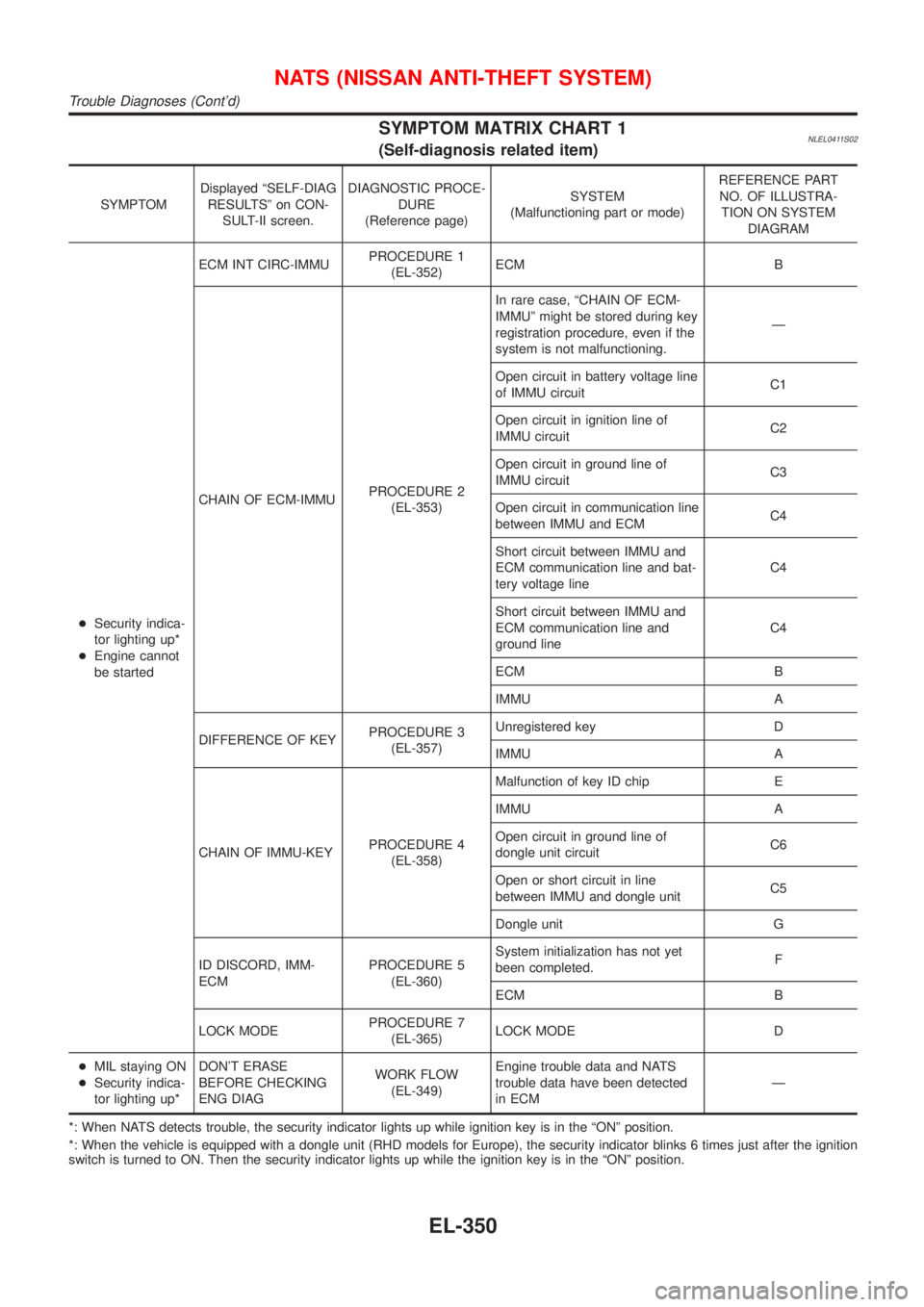
SYMPTOM MATRIX CHART 1NLEL0411S02(Self-diagnosis related item)
SYMPTOMDisplayed ªSELF-DIAG
RESULTSº on CON-
SULT-II screen.DIAGNOSTIC PROCE-
DURE
(Reference page)SYSTEM
(Malfunctioning part or mode)REFERENCE PART
NO. OF ILLUSTRA-
TION ON SYSTEM
DIAGRAM
+Security indica-
tor lighting up*
+Engine cannot
be startedECM INT CIRC-IMMUPROCEDURE 1
(EL-352)ECM B
CHAIN OF ECM-IMMUPROCEDURE 2
(EL-353)In rare case, ªCHAIN OF ECM-
IMMUº might be stored during key
registration procedure, even if the
system is not malfunctioning.Ð
Open circuit in battery voltage line
of IMMU circuitC1
Open circuit in ignition line of
IMMU circuitC2
Open circuit in ground line of
IMMU circuitC3
Open circuit in communication line
between IMMU and ECMC4
Short circuit between IMMU and
ECM communication line and bat-
tery voltage lineC4
Short circuit between IMMU and
ECM communication line and
ground lineC4
ECM B
IMMU A
DIFFERENCE OF KEYPROCEDURE 3
(EL-357)Unregistered key D
IMMU A
CHAIN OF IMMU-KEYPROCEDURE 4
(EL-358)Malfunction of key ID chip E
IMMU A
Open circuit in ground line of
dongle unit circuitC6
Open or short circuit in line
between IMMU and dongle unitC5
Dongle unit G
ID DISCORD, IMM-
ECMPROCEDURE 5
(EL-360)System initialization has not yet
been completed.F
ECM B
LOCK MODEPROCEDURE 7
(EL-365)LOCK MODE D
+MIL staying ON
+Security indica-
tor lighting up*DON'T ERASE
BEFORE CHECKING
ENG DIAGWORK FLOW
(EL-349)Engine trouble data and NATS
trouble data have been detected
in ECMÐ
*: When NATS detects trouble, the security indicator lights up while ignition key is in the ªONº position.
*: When the vehicle is equipped with a dongle unit (RHD models for Europe), the security indicator blinks 6 times just after the ignition
switch is turned to ON. Then the security indicator lights up while the ignition key is in the ªONº position.
NATS (NISSAN ANTI-THEFT SYSTEM)
Trouble Diagnoses (Cont'd)
EL-350
Page 2526 of 3051

SEF122U
Checking Water in Fuel Filter Sensor (where
fitted)
NLFE00251. Remove the connector from filter and water in fuel filter sen-
sor.
2. Turn the key switch“ON”. Lift the float to ensure that the
warning lamp turns on.
Water in fuel filter sensor tightening torque:
: 3.9 - 5.9 N·m (0.4 - 0.6 kg-m, 35 - 52 in-lb)
Discard the old O-ring and replace it with a new one.
Removal and InstallationNLFE0015WARNING:
When replacing fuel line parts, be sure to observe the following.
+Put a“CAUTION: FLAMMABLE”sign in workshop.
+Be sure to furnish workshop with a CO
2fire extinguisher.
+Do not smoke while servicing fuel system. Keep open flames and sparks away from work area.
CAUTION:
+Before removing fuel line parts, carry out the following procedures:
a) Put drained fuel in an explosion-proof container and put the lid on securely.
b) Disconnect battery ground cable.
+Always replace O-ring and clamps with new ones.
+Do not kink or twist tubes when they are being installed.
+Do not tighten hose clamps excessively to avoid damaging hoses.
+After installing tubes, run engine and check for fuel leaks at connections.
FUEL SYSTEMYD
Checking Water in Fuel Filter Sensor (where fitted)
FE-17