2001 NISSAN ALMERA TINO AUX
[x] Cancel search: AUXPage 429 of 3051
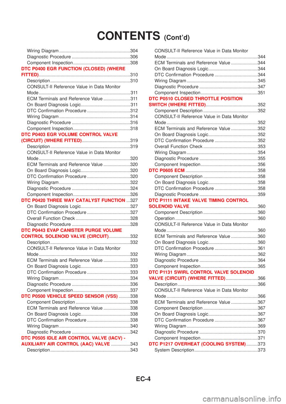
Wiring Diagram ........................................................304
Diagnostic Procedure ..............................................306
Component Inspection .............................................308
DTC P0400 EGR FUNCTION (CLOSED) (WHERE
FITTED)........................................................................310
Description ...............................................................310
CONSULT-II Reference Value in Data Monitor
Mode ........................................................................ 311
ECM Terminals and Reference Value ..................... 311
On Board Diagnosis Logic....................................... 311
DTC Confirmation Procedure ..................................312
Wiring Diagram ........................................................314
Diagnostic Procedure ..............................................316
Component Inspection .............................................318
DTC P0403 EGR VOLUME CONTROL VALVE
(CIRCUIT) (WHERE FITTED)......................................319
Description ...............................................................319
CONSULT-II Reference Value in Data Monitor
Mode ........................................................................320
ECM Terminals and Reference Value .....................320
On Board Diagnosis Logic.......................................320
DTC Confirmation Procedure ..................................320
Wiring Diagram ........................................................322
Diagnostic Procedure ..............................................324
Component Inspection .............................................326
DTC P0420 THREE WAY CATALYST FUNCTION...327
On Board Diagnosis Logic.......................................327
DTC Confirmation Procedure ..................................327
Overall Function Check ...........................................328
Diagnostic Procedure ..............................................328
DTC P0443 EVAP CANISTER PURGE VOLUME
CONTROL SOLENOID VALVE (CIRCUIT).................332
Description ...............................................................332
CONSULT-II Reference Value in Data Monitor
Mode ........................................................................332
ECM Terminals and Reference Value .....................333
On Board Diagnosis Logic.......................................333
DTC Confirmation Procedure ..................................333
Wiring Diagram ........................................................334
Diagnostic Procedure ..............................................336
Component Inspection .............................................337
DTC P0500 VEHICLE SPEED SENSOR (VSS).........338
Component Description ...........................................338
ECM Terminals and Reference Value .....................338
On Board Diagnosis Logic.......................................338
DTC Confirmation Procedure ..................................338
Wiring Diagram ........................................................340
Diagnostic Procedure ..............................................342
DTC P0505 IDLE AIR CONTROL VALVE (IACV) -
AUXILIARY AIR CONTROL (AAC) VALVE...............343
Description ...............................................................343CONSULT-II Reference Value in Data Monitor
Mode ........................................................................344
ECM Terminals and Reference Value .....................344
On Board Diagnosis Logic.......................................344
DTC Confirmation Procedure ..................................344
Wiring Diagram ........................................................345
Diagnostic Procedure ..............................................347
Component Inspection .............................................351
DTC P0510 CLOSED THROTTLE POSITION
SWITCH (WHERE FITTED).........................................352
Component Description ...........................................352
CONSULT-II Reference Value in Data Monitor
Mode ........................................................................352
ECM Terminals and Reference Value .....................352
On Board Diagnosis Logic.......................................352
DTC Confirmation Procedure ..................................352
Overall Function Check ...........................................353
Wiring Diagram ........................................................354
Diagnostic Procedure ..............................................355
Component Inspection .............................................356
DTC P0605 ECM.........................................................358
Component Description ...........................................358
On Board Diagnosis Logic.......................................358
DTC Confirmation Procedure ..................................358
Diagnostic Procedure ..............................................359
D T C P 1111INTAKE VALVE TIMING CONTROL
SOLENOID VALVE......................................................360
Component Description ...........................................360
Operation .................................................................360
CONSULT-II Reference Value in Data Monitor
Mode ........................................................................360
ECM Terminals and Reference Value .....................360
On Board Diagnosis Logic.......................................360
DTC Confirmation Procedure ..................................361
Wiring Diagram ........................................................362
Diagnostic Procedure ..............................................364
Component Inspection .............................................365
DTC P1131 SWIRL CONTROL VALVE SOLENOID
VALVE (CIRCUIT) (WHERE FITTED).........................366
Description ...............................................................366
CONSULT-II Reference Value in Data Monitor
Mode ........................................................................366
ECM Terminals and Reference Value .....................367
Component Description ...........................................367
On Board Diagnosis Logic.......................................367
DTC Confirmation Procedure ..................................367
Wiring Diagram ........................................................369
Diagnostic Procedure ..............................................370
Component Inspection .............................................371
DTC P1217 OVERHEAT (COOLING SYSTEM).........373
System Description ..................................................373
CONTENTS(Cont'd)
EC-4
Page 430 of 3051
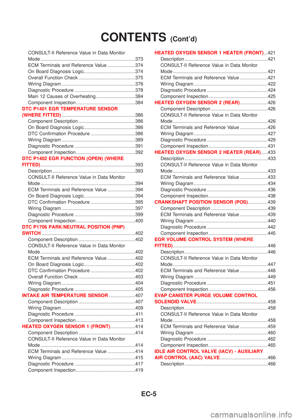
CONSULT-II Reference Value in Data Monitor
Mode ........................................................................373
ECM Terminals and Reference Value .....................374
On Board Diagnosis Logic.......................................374
Overall Function Check ...........................................375
Wiring Diagram ........................................................376
Diagnostic Procedure ..............................................378
Main 12 Causes of Overheating..............................384
Component Inspection .............................................384
DTC P1401 EGR TEMPERATURE SENSOR
(WHERE FITTED)........................................................386
Component Description ...........................................386
On Board Diagnosis Logic.......................................386
DTC Confirmation Procedure ..................................386
Wiring Diagram ........................................................389
Diagnostic Procedure ..............................................391
Component Inspection .............................................392
DTC P1402 EGR FUNCTION (OPEN) (WHERE
FITTED)........................................................................393
Description ...............................................................393
CONSULT-II Reference Value in Data Monitor
Mode ........................................................................394
ECM Terminals and Reference Value .....................394
On Board Diagnosis Logic.......................................394
DTC Confirmation Procedure ..................................395
Wiring Diagram ........................................................397
Diagnostic Procedure ..............................................399
Component Inspection .............................................400
DTC P1706 PARK/NEUTRAL POSITION (PNP)
SWITCH.......................................................................402
Component Description ...........................................402
CONSULT-II Reference Value in Data Monitor
Mode ........................................................................402
ECM Terminals and Reference Value .....................402
On Board Diagnosis Logic.......................................402
DTC Confirmation Procedure ..................................402
Overall Function Check ...........................................403
Wiring Diagram ........................................................404
Diagnostic Procedure ..............................................405
INTAKE AIR TEMPERATURE SENSOR....................407
Component Description ...........................................407
Wiring Diagram ........................................................409
Diagnostic Procedure .............................................. 411
Component Inspection .............................................413
HEATED OXYGEN SENSOR 1 (FRONT)...................414
Component Description ...........................................414
CONSULT-II Reference Value in Data Monitor
Mode ........................................................................414
ECM Terminals and Reference Value .....................414
Wiring Diagram ........................................................415
Diagnostic Procedure ..............................................417
Component Inspection .............................................419HEATED OXYGEN SENSOR 1 HEATER (FRONT)...421
Description ...............................................................421
CONSULT-II Reference Value in Data Monitor
Mode ........................................................................421
ECM Terminals and Reference Value .....................421
Wiring Diagram ........................................................422
Diagnostic Procedure ..............................................424
Component Inspection .............................................425
HEATED OXYGEN SENSOR 2 (REAR).....................426
Component Description ...........................................426
CONSULT-II Reference Value in Data Monitor
Mode ........................................................................426
ECM Terminals and Reference Value .....................426
Wiring Diagram ........................................................427
Diagnostic Procedure ..............................................429
Component Inspection .............................................431
HEATED OXYGEN SENSOR 2 HEATER (REAR).....433
Description ...............................................................433
CONSULT-II Reference Value in Data Monitor
Mode ........................................................................433
ECM Terminals and Reference Value .....................433
Wiring Diagram ........................................................434
Diagnostic Procedure ..............................................436
Component Inspection .............................................438
CRANKSHAFT POSITION SENSOR (POS)...............439
Component Description ...........................................439
ECM Terminals and Reference Value .....................439
Wiring Diagram ........................................................440
Diagnostic Procedure ..............................................442
Component Inspection .............................................445
EGR VOLUME CONTROL SYSTEM (WHERE
FITTED)........................................................................446
Description ...............................................................446
CONSULT-II Reference Value in Data Monitor
Mode ........................................................................447
ECM Terminals and Reference Value .....................448
Wiring Diagram ........................................................449
Diagnostic Procedure ..............................................451
Component Inspection .............................................456
EVAP CANISTER PURGE VOLUME CONTROL
SOLENOID VALVE......................................................458
Description ...............................................................458
CONSULT-II Reference Value in Data Monitor
Mode ........................................................................458
ECM Terminals and Reference Value .....................459
Wiring Diagram ........................................................460
Diagnostic Procedure ..............................................462
Component Inspection .............................................465
IDLE AIR CONTROL VALVE (IACV) - AUXILIARY
AIR CONTROL (AAC) VALVE....................................466
Description ...............................................................466
CONTENTS(Cont'd)
EC-5
Page 435 of 3051
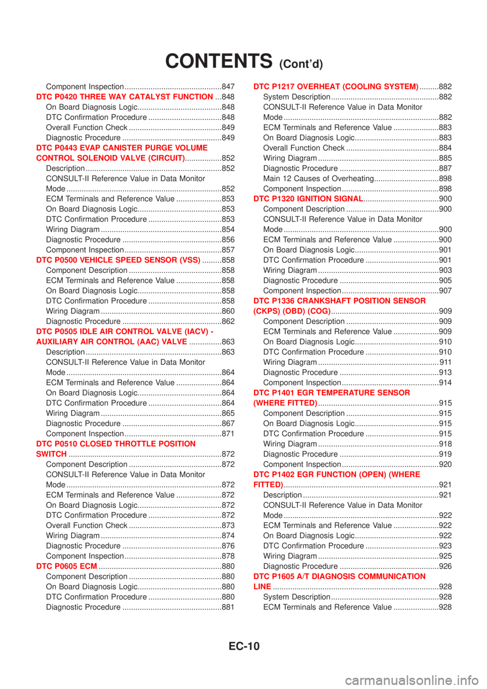
Component Inspection .............................................847
DTC P0420 THREE WAY CATALYST FUNCTION...848
On Board Diagnosis Logic.......................................848
DTC Confirmation Procedure ..................................848
Overall Function Check ...........................................849
Diagnostic Procedure ..............................................849
DTC P0443 EVAP CANISTER PURGE VOLUME
CONTROL SOLENOID VALVE (CIRCUIT).................852
Description ...............................................................852
CONSULT-II Reference Value in Data Monitor
Mode ........................................................................852
ECM Terminals and Reference Value .....................853
On Board Diagnosis Logic.......................................853
DTC Confirmation Procedure ..................................853
Wiring Diagram ........................................................854
Diagnostic Procedure ..............................................856
Component Inspection .............................................857
DTC P0500 VEHICLE SPEED SENSOR (VSS).........858
Component Description ...........................................858
ECM Terminals and Reference Value .....................858
On Board Diagnosis Logic.......................................858
DTC Confirmation Procedure ..................................858
Wiring Diagram ........................................................860
Diagnostic Procedure ..............................................862
DTC P0505 IDLE AIR CONTROL VALVE (IACV) -
AUXILIARY AIR CONTROL (AAC) VALVE...............863
Description ...............................................................863
CONSULT-II Reference Value in Data Monitor
Mode ........................................................................864
ECM Terminals and Reference Value .....................864
On Board Diagnosis Logic.......................................864
DTC Confirmation Procedure ..................................864
Wiring Diagram ........................................................865
Diagnostic Procedure ..............................................867
Component Inspection .............................................871
DTC P0510 CLOSED THROTTLE POSITION
SWITCH.......................................................................872
Component Description ...........................................872
CONSULT-II Reference Value in Data Monitor
Mode ........................................................................872
ECM Terminals and Reference Value .....................872
On Board Diagnosis Logic.......................................872
DTC Confirmation Procedure ..................................872
Overall Function Check ...........................................873
Wiring Diagram ........................................................874
Diagnostic Procedure ..............................................876
Component Inspection .............................................878
DTC P0605 ECM.........................................................880
Component Description ...........................................880
On Board Diagnosis Logic.......................................880
DTC Confirmation Procedure ..................................880
Diagnostic Procedure ..............................................881DTC P1217 OVERHEAT (COOLING SYSTEM).........882
System Description ..................................................882
CONSULT-II Reference Value in Data Monitor
Mode ........................................................................882
ECM Terminals and Reference Value .....................883
On Board Diagnosis Logic.......................................883
Overall Function Check ...........................................884
Wiring Diagram ........................................................885
Diagnostic Procedure ..............................................887
Main 12 Causes of Overheating..............................898
Component Inspection .............................................898
DTC P1320 IGNITION SIGNAL...................................900
Component Description ...........................................900
CONSULT-II Reference Value in Data Monitor
Mode ........................................................................900
ECM Terminals and Reference Value .....................900
On Board Diagnosis Logic.......................................901
DTC Confirmation Procedure ..................................901
Wiring Diagram ........................................................903
Diagnostic Procedure ..............................................905
Component Inspection .............................................907
DTC P1336 CRANKSHAFT POSITION SENSOR
(CKPS) (OBD) (COG)..................................................909
Component Description ...........................................909
ECM Terminals and Reference Value .....................909
On Board Diagnosis Logic.......................................910
DTC Confirmation Procedure ..................................910
Wiring Diagram ........................................................ 911
Diagnostic Procedure ..............................................913
Component Inspection .............................................914
DTC P1401 EGR TEMPERATURE SENSOR
(WHERE FITTED)........................................................915
Component Description ...........................................915
On Board Diagnosis Logic.......................................915
DTC Confirmation Procedure ..................................915
Wiring Diagram ........................................................918
Diagnostic Procedure ..............................................919
Component Inspection .............................................920
DTC P1402 EGR FUNCTION (OPEN) (WHERE
FITTED)........................................................................921
Description ...............................................................921
CONSULT-II Reference Value in Data Monitor
Mode ........................................................................922
ECM Terminals and Reference Value .....................922
On Board Diagnosis Logic.......................................922
DTC Confirmation Procedure ..................................923
Wiring Diagram ........................................................925
Diagnostic Procedure ..............................................926
DTC P1605 A/T DIAGNOSIS COMMUNICATION
LINE.............................................................................928
System Description ..................................................928
ECM Terminals and Reference Value .....................928
CONTENTS(Cont'd)
EC-10
Page 436 of 3051
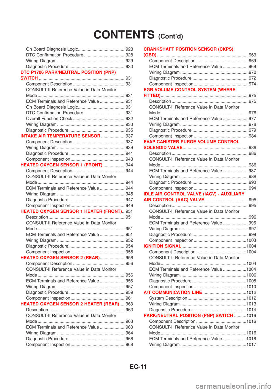
On Board Diagnosis Logic.......................................928
DTC Confirmation Procedure ..................................928
Wiring Diagram ........................................................929
Diagnostic Procedure ..............................................930
DTC P1706 PARK/NEUTRAL POSITION (PNP)
SWITCH.......................................................................931
Component Description ...........................................931
CONSULT-II Reference Value in Data Monitor
Mode ........................................................................931
ECM Terminals and Reference Value .....................931
On Board Diagnosis Logic.......................................931
DTC Confirmation Procedure ..................................931
Overall Function Check ...........................................932
Wiring Diagram ........................................................933
Diagnostic Procedure ..............................................935
INTAKE AIR TEMPERATURE SENSOR....................937
Component Description ...........................................937
Wiring Diagram ........................................................939
Diagnostic Procedure ..............................................941
Component Inspection .............................................943
HEATED OXYGEN SENSOR 1 (FRONT)...................944
Component Description ...........................................944
CONSULT-II Reference Value in Data Monitor
Mode ........................................................................944
ECM Terminals and Reference Value .....................944
Wiring Diagram ........................................................945
Diagnostic Procedure ..............................................947
Component Inspection .............................................949
HEATED OXYGEN SENSOR 1 HEATER (FRONT)...951
Description ...............................................................951
CONSULT-II Reference Value in Data Monitor
Mode ........................................................................951
ECM Terminals and Reference Value .....................951
Wiring Diagram ........................................................952
Diagnostic Procedure ..............................................954
Component Inspection .............................................955
HEATED OXYGEN SENSOR 2 (REAR).....................956
Component Description ...........................................956
CONSULT-II Reference Value in Data Monitor
Mode ........................................................................956
ECM Terminals and Reference Value .....................956
Wiring Diagram ........................................................957
Diagnostic Procedure ..............................................959
Component Inspection .............................................961
HEATED OXYGEN SENSOR 2 HEATER (REAR).....963
Description ...............................................................963
CONSULT-II Reference Value in Data Monitor
Mode ........................................................................963
ECM Terminals and Reference Value .....................963
Wiring Diagram ........................................................964
Diagnostic Procedure ..............................................966
Component Inspection .............................................968CRANKSHAFT POSITION SENSOR (CKPS)
(OBD)...........................................................................969
Component Description ...........................................969
ECM Terminals and Reference Value .....................969
Wiring Diagram ........................................................970
Diagnostic Procedure ..............................................972
Component Inspection .............................................974
EGR VOLUME CONTROL SYSTEM (WHERE
FITTED)........................................................................975
Description ...............................................................975
CONSULT-II Reference Value in Data Monitor
Mode ........................................................................976
ECM Terminals and Reference Value .....................977
Wiring Diagram ........................................................978
Diagnostic Procedure ..............................................979
Component Inspection .............................................984
EVAP CANISTER PURGE VOLUME CONTROL
SOLENOID VALVE......................................................986
Description ...............................................................986
CONSULT-II Reference Value in Data Monitor
Mode ........................................................................986
ECM Terminals and Reference Value .....................987
Wiring Diagram ........................................................988
Diagnostic Procedure ..............................................990
Component Inspection .............................................994
IDLE AIR CONTROL VALVE (IACV) - AUXILIARY
AIR CONTROL (AAC) VALVE....................................995
Description ...............................................................995
CONSULT-II Reference Value in Data Monitor
Mode ........................................................................996
ECM Terminals and Reference Value .....................996
Wiring Diagram ........................................................997
Diagnostic Procedure ..............................................999
Component Inspection ...........................................1003
IGNITION SIGNAL.....................................................1004
Component Description .........................................1004
CONSULT-II Reference Value in Data Monitor
Mode ......................................................................1004
ECM Terminals and Reference Value ...................1004
Wiring Diagram ......................................................1006
Diagnostic Procedure ............................................1008
Component Inspection ...........................................1010
A/T COMMUNICATION LINE....................................1012
System Description ................................................1012
Wiring Diagram ......................................................1013
Diagnostic Procedure ............................................1014
PARK/NEUTRAL POSITION (PNP) SWITCH..........1016
Component Description .........................................1016
CONSULT-II Reference Value in Data Monitor
Mode ......................................................................1016
ECM Terminals and Reference Value ...................1016
Wiring Diagram ......................................................1017
CONTENTS(Cont'd)
EC-11
Page 768 of 3051
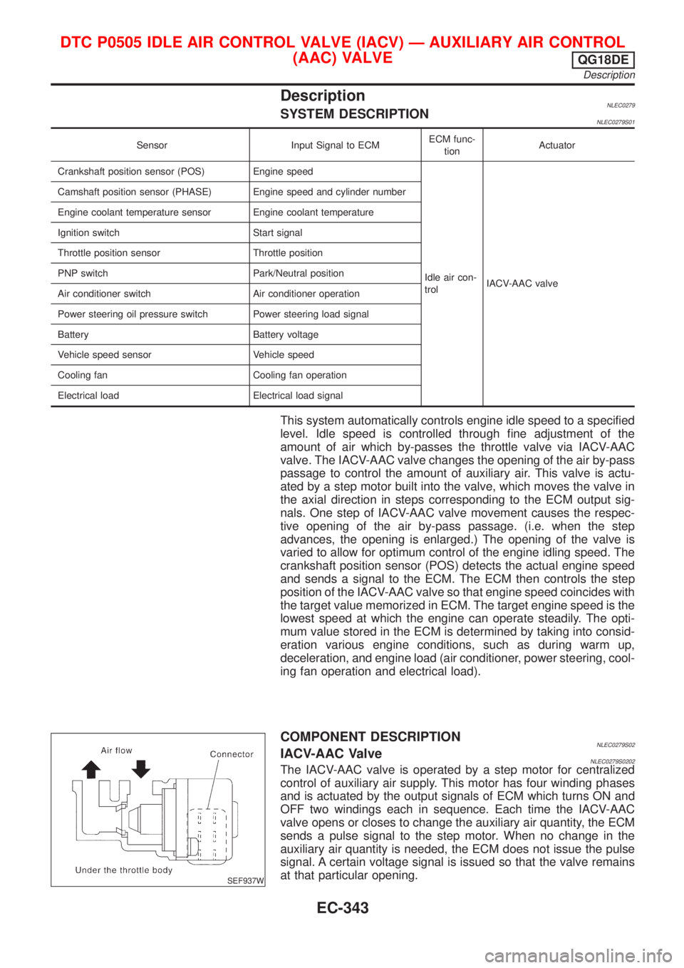
DescriptionNLEC0279SYSTEM DESCRIPTIONNLEC0279S01
Sensor Input Signal to ECMECM func-
tionActuator
Crankshaft position sensor (POS) Engine speed
Idle air con-
trolIACV-AAC valve Camshaft position sensor (PHASE) Engine speed and cylinder number
Engine coolant temperature sensor Engine coolant temperature
Ignition switch Start signal
Throttle position sensor Throttle position
PNP switch Park/Neutral position
Air conditioner switch Air conditioner operation
Power steering oil pressure switch Power steering load signal
Battery Battery voltage
Vehicle speed sensor Vehicle speed
Cooling fan Cooling fan operation
Electrical load Electrical load signal
This system automatically controls engine idle speed to a specified
level. Idle speed is controlled through fine adjustment of the
amount of air which by-passes the throttle valve via IACV-AAC
valve. The IACV-AAC valve changes the opening of the air by-pass
passage to control the amount of auxiliary air. This valve is actu-
ated by a step motor built into the valve, which moves the valve in
the axial direction in steps corresponding to the ECM output sig-
nals. One step of IACV-AAC valve movement causes the respec-
tive opening of the air by-pass passage. (i.e. when the step
advances, the opening is enlarged.) The opening of the valve is
varied to allow for optimum control of the engine idling speed. The
crankshaft position sensor (POS) detects the actual engine speed
and sends a signal to the ECM. The ECM then controls the step
position of the IACV-AAC valve so that engine speed coincides with
the target value memorized in ECM. The target engine speed is the
lowest speed at which the engine can operate steadily. The opti-
mum value stored in the ECM is determined by taking into consid-
eration various engine conditions, such as during warm up,
deceleration, and engine load (air conditioner, power steering, cool-
ing fan operation and electrical load).
SEF937W
COMPONENT DESCRIPTIONNLEC0279S02IACV-AAC ValveNLEC0279S0202The IACV-AAC valve is operated by a step motor for centralized
control of auxiliary air supply. This motor has four winding phases
and is actuated by the output signals of ECM which turns ON and
OFF two windings each in sequence. Each time the IACV-AAC
valve opens or closes to change the auxiliary air quantity, the ECM
sends a pulse signal to the step motor. When no change in the
auxiliary air quantity is needed, the ECM does not issue the pulse
signal. A certain voltage signal is issued so that the valve remains
at that particular opening.
DTC P0505 IDLE AIR CONTROL VALVE (IACV) Ð AUXILIARY AIR CONTROL
(AAC) VALVE
QG18DE
Description
EC-343
Page 769 of 3051
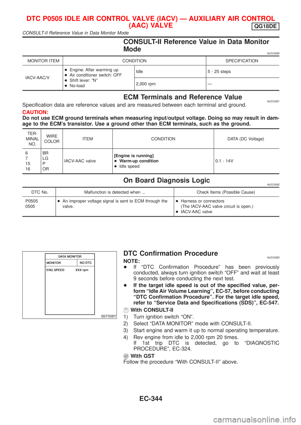
CONSULT-II Reference Value in Data Monitor
Mode
NLEC0280
MONITOR ITEM CONDITION SPECIFICATION
IACV-AAC/V+Engine: After warming up
+Air conditioner switch: OFF
+Shift lever: ªNº
+No-loadIdle 5 - 25 steps
2,000 rpm Ð
ECM Terminals and Reference ValueNLEC0281Specification data are reference values and are measured between each terminal and ground.
CAUTION:
Do not use ECM ground terminals when measuring input/output voltage. Doing so may result in dam-
age to the ECM's transistor. Use a ground other than ECM terminals, such as the ground.
TER-
MINAL
NO.WIRE
COLORITEM CONDITION DATA (DC Voltage)
6
7
15
16BR
LG
P
ORIACV-AAC valve[Engine is running]
+Warm-up condition
+Idle speed0.1 - 14V
On Board Diagnosis LogicNLEC0282
DTC No. Malfunction is detected when ... Check Items (Possible Cause)
P0505
0505+An improper voltage signal is sent to ECM through the
valve.+Harness or connectors
(The IACV-AAC valve circuit is open.)
+IACV-AAC valve
SEF058Y
DTC Confirmation ProcedureNLEC0283NOTE:
+If ªDTC Confirmation Procedureº has been previously
conducted, always turn ignition switch ªOFFº and wait at least
9 seconds before conducting the next test.
+If the target idle speed is out of the specified value, per-
form ªIdle Air Volume Learningº, EC-57, before conducting
ªDTC Confirmation Procedureº. For the target idle speed,
refer to ªService Data and Specifications (SDS)º, EC-547.
With CONSULT-II
1) Turn ignition switch ªONº.
2) Select ªDATA MONITORº mode with CONSULT-II.
3) Start engine and warm it up to normal operating temperature.
4) Rev engine from idle to 2,000 rpm 20 times.
If 1st trip DTC is detected, go to ªDIAGNOSTIC
PROCEDUREº, EC-324.
With GST
Follow the procedure ªWith CONSULT-IIº above.
DTC P0505 IDLE AIR CONTROL VALVE (IACV) Ð AUXILIARY AIR CONTROL
(AAC) VALVE
QG18DE
CONSULT-II Reference Value in Data Monitor Mode
EC-344
Page 770 of 3051
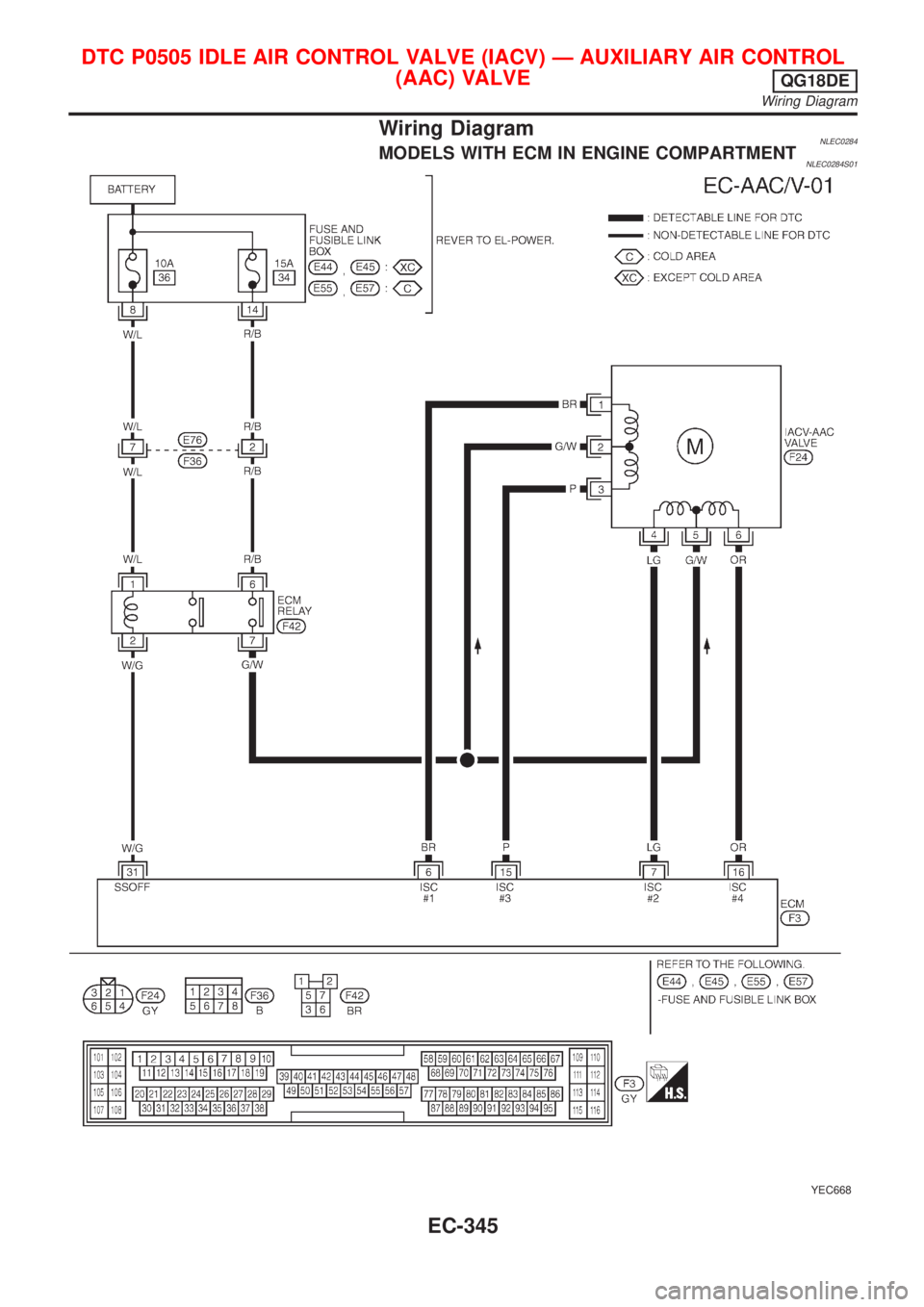
Wiring DiagramNLEC0284MODELS WITH ECM IN ENGINE COMPARTMENTNLEC0284S01
YEC668
DTC P0505 IDLE AIR CONTROL VALVE (IACV) Ð AUXILIARY AIR CONTROL
(AAC) VALVE
QG18DE
Wiring Diagram
EC-345
Page 771 of 3051
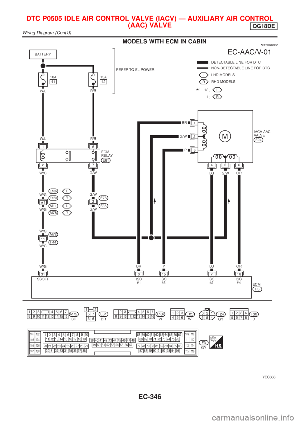
MODELS WITH ECM IN CABINNLEC0284S02
YEC888
DTC P0505 IDLE AIR CONTROL VALVE (IACV) Ð AUXILIARY AIR CONTROL
(AAC) VALVE
QG18DE
Wiring Diagram (Cont'd)
EC-346