2001 NISSAN ALMERA TINO fuel filter
[x] Cancel search: fuel filterPage 417 of 3051
SCL729
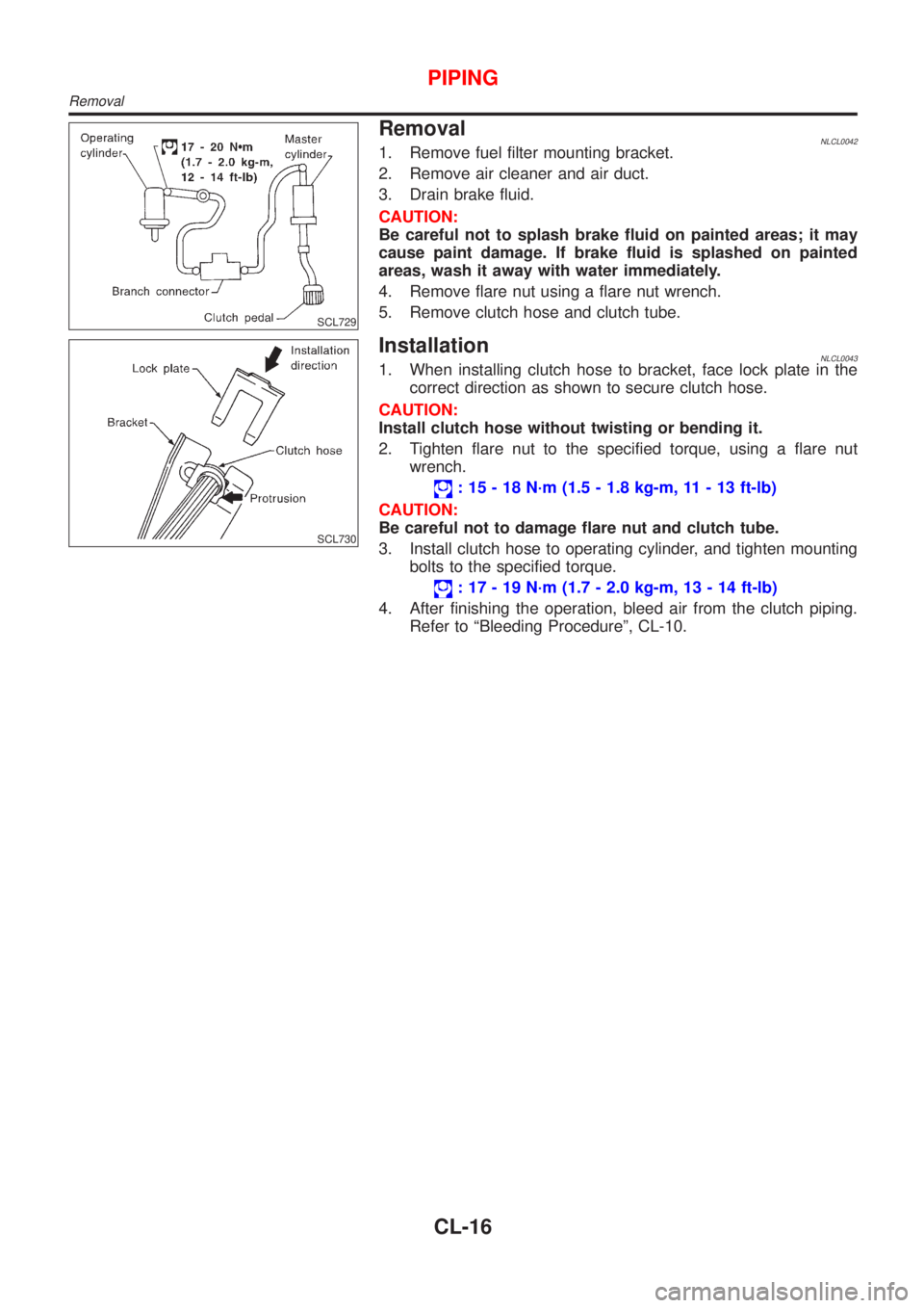
RemovalNLCL00421. Remove fuel filter mounting bracket.
2. Remove air cleaner and air duct.
3. Drain brake fluid.
CAUTION:
Be careful not to splash brake fluid on painted areas; it may
cause paint damage. If brake fluid is splashed on painted
areas, wash it away with water immediately.
4. Remove flare nut using a flare nut wrench.
5. Remove clutch hose and clutch tube.
SCL730
InstallationNLCL00431. When installing clutch hose to bracket, face lock plate in the
correct direction as shown to secure clutch hose.
CAUTION:
Install clutch hose without twisting or bending it.
2. Tighten flare nut to the specified torque, using a flare nut
wrench.
: 15 - 18 N´m (1.5 - 1.8 kg-m, 11 - 13 ft-lb)
CAUTION:
Be careful not to damage flare nut and clutch tube.
3. Install clutch hose to operating cylinder, and tighten mounting
bolts to the specified torque.
: 17 - 19 N´m (1.7 - 2.0 kg-m, 13 - 14 ft-lb)
4. After finishing the operation, bleed air from the clutch piping.
Refer to ªBleeding Procedureº, CL-10.
PIPING
Removal
CL-16
Page 437 of 3051
Diagnostic Procedure ............................................1019
INJECTOR.................................................................1021
Component Description .........................................1021
CONSULT-II Reference Value in Data Monitor
Mode ......................................................................1021
ECM Terminals and Reference Value ...................1021
Wiring Diagram ......................................................1022
Diagnostic Procedure ............................................1024
Component Inspection ...........................................1026
START SIGNAL.........................................................1027
CONSULT-II Reference Value in Data Monitor
Mode ......................................................................1027
ECM Terminals and Reference Value ...................1027
Wiring Diagram ......................................................1028
Diagnostic Procedure ............................................1030
FUEL PUMP...............................................................1032
System Description ................................................1032
Component Description .........................................1032
CONSULT-II Reference Value in Data Monitor
Mode ......................................................................1032
ECM Terminals and Reference Value ...................1033
Wiring Diagram ......................................................1034
Diagnostic Procedure ............................................1036
Component Inspection ...........................................1038
POWER STEERING OIL PRESSURE SWITCH.......1039
Component Description .........................................1039
CONSULT-II Reference Value in Data Monitor
Mode ......................................................................1039
ECM Terminals and Reference Value ...................1039
Wiring Diagram ......................................................1040
Diagnostic Procedure ............................................1041
Component Inspection ...........................................1043
REFRIGERANT PRESSURE SENSOR....................1044
Description .............................................................1044
ECM Terminals and Reference Value ...................1044
Wiring Diagram ......................................................1045
Diagnostic Procedure ............................................1047
ELECTRICAL LOAD SIGNAL...................................1050
CONSULT-II Reference Value in Data Monitor
Mode ......................................................................1050
ECM Terminals and Reference Value ...................1050
Wiring Diagram ......................................................1051
Diagnostic Procedure - Load Signal - ...................1055
Diagnostic Procedure - Heater Control Panel
(Fan Switch) - ........................................................1059
MI & DATA LINK CONNECTORS............................1060
Wiring Diagram ......................................................1060
SERVICE DATA AND SPECIFICATIONS (SDS).....1062
Fuel Pressure Regulator........................................1062
Idle Speed and Ignition Timing ..............................1062
Ignition Coil ............................................................1062
Mass Air Flow Sensor............................................1062Engine Coolant Temperature Sensor ....................1062
EGR Volume Control Valve (where fitted) .............1062
EGR Temperature Sensor (where fitted) ...............1062
Fuel Pump .............................................................1063
IACV-AAC Valve ....................................................1063
Injector ...................................................................1063
Resistor ..................................................................1063
Throttle Position Sensor ........................................1063
Heated Oxygen Sensor 1 (Front) Heater ..............1063
Intake Air Temperature Sensor ..............................1063
EVAP Canister Purge Volume Control Valve ........1063
Heated Oxygen Sensor 2 (Rear) Heater...............1063
Crankshaft Position Sensor (OBD)........................1063
YD22DDTI
TROUBLE DIAGNOSIS - INDEX..............................1064
Alphabetical & P No. Index for DTC .....................1064
PRECAUTIONS.........................................................1066
Precautions for Supplemental Restraint System
(SRS)²AIR BAG²and²SEAT BELT
PRE-TENSIONER²................................................1066
Engine Fuel & Emission Control System ..............1066
Wiring Diagrams and Trouble Diagnosis ...............1069
PREPARATION.........................................................1070
Special Service Tools ............................................1070
ENGINE AND EMISSION CONTROL OVERALL
SYSTEM.....................................................................1071
Engine Control Component Parts Location ...........1071
Circuit Diagram ......................................................1074
System Diagram ....................................................1076
Vacuum Hose Drawing ..........................................1077
System Chart .........................................................1078
ENGINE AND EMISSION BASIC CONTROL
SYSTEM DESCRIPTION...........................................1079
Fuel Injection Control System ...............................1079
Fuel Injection Timing Control System....................1080
Air Conditioning Cut Control ..................................1081
Fuel Cut Control (at no load & high engine
speed) ....................................................................1081
Crankcase Ventilation System ...............................1082
BASIC SERVICE PROCEDURE...............................1083
Injection Tube and Injection Nozzle ......................1083
Electronic Control Fuel Injection Pump .................1087
Fuel Filter ...............................................................1094
ON BOARD DIAGNOSTIC SYSTEM
DESCRIPTION...........................................................1096
DTC and MI Detection Logic .................................1096
Diagnostic Trouble Code (DTC) ............................1096
NATS (Nissan Anti-Theft System) .........................1097
Malfunction Indicator (MI) ......................................1097
CONSULT-II ........................................................... 1102
CONTENTS(Cont'd)
EC-12
Page 468 of 3051
SEF094Y
SEF214Y
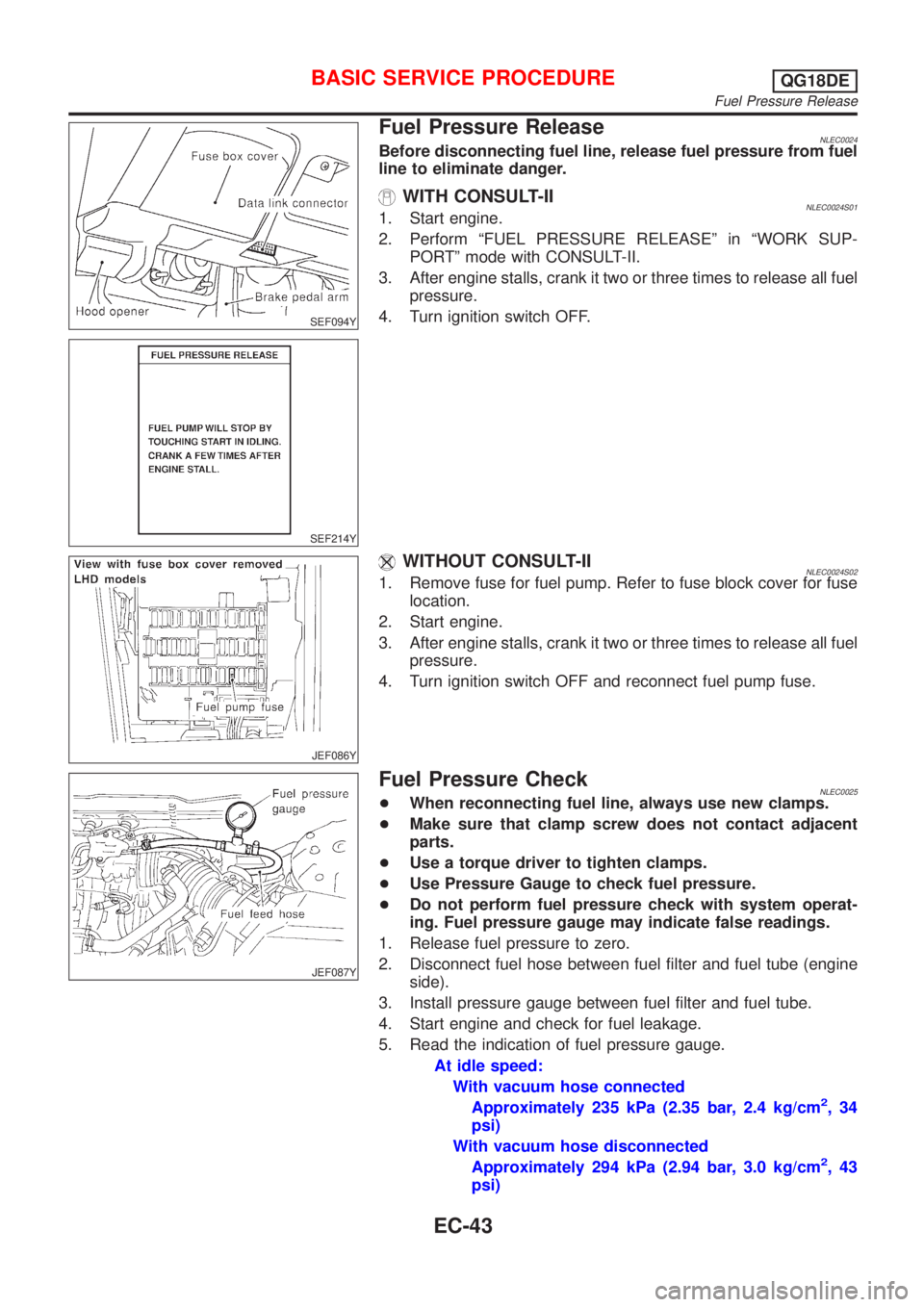
Fuel Pressure ReleaseNLEC0024Before disconnecting fuel line, release fuel pressure from fuel
line to eliminate danger.
WITH CONSULT-IINLEC0024S011. Start engine.
2. Perform ªFUEL PRESSURE RELEASEº in ªWORK SUP-
PORTº mode with CONSULT-II.
3. After engine stalls, crank it two or three times to release all fuel
pressure.
4. Turn ignition switch OFF.
JEF086Y
WITHOUT CONSULT-IINLEC0024S021. Remove fuse for fuel pump. Refer to fuse block cover for fuse
location.
2. Start engine.
3. After engine stalls, crank it two or three times to release all fuel
pressure.
4. Turn ignition switch OFF and reconnect fuel pump fuse.
JEF087Y
Fuel Pressure CheckNLEC0025+When reconnecting fuel line, always use new clamps.
+Make sure that clamp screw does not contact adjacent
parts.
+Use a torque driver to tighten clamps.
+Use Pressure Gauge to check fuel pressure.
+Do not perform fuel pressure check with system operat-
ing. Fuel pressure gauge may indicate false readings.
1. Release fuel pressure to zero.
2. Disconnect fuel hose between fuel filter and fuel tube (engine
side).
3. Install pressure gauge between fuel filter and fuel tube.
4. Start engine and check for fuel leakage.
5. Read the indication of fuel pressure gauge.
At idle speed:
With vacuum hose connected
Approximately 235 kPa (2.35 bar, 2.4 kg/cm
2,34
psi)
With vacuum hose disconnected
Approximately 294 kPa (2.94 bar, 3.0 kg/cm
2,43
psi)
BASIC SERVICE PROCEDUREQG18DE
Fuel Pressure Release
EC-43
Page 552 of 3051
SYMPTOM
Reference
page
HARD/NO START/RESTART (EXCP. HA)
ENGINE STALL
HESITATION/SURGING/FLAT SPOT
SPARK KNOCK/DETONATION
LACK OF POWER/POOR ACCELERATION
HIGH IDLE/LOW IDLE
ROUGH IDLE/HUNTING
IDLING VIBRATION
SLOW/NO RETURN TO IDLE
OVERHEATS/WATER TEMPERATURE HIGH
EXCESSIVE FUEL CONSUMPTION
EXCESSIVE OIL CONSUMPTION
BATTERY DEAD (UNDER CHARGE)
Warranty symptom code AA AB AC AD AE AF AG AH AJ AK AL AM HA
Engine Cylinder head
55555 55 5
EM section Cylinder head gasket 4 3
Cylinder block
66666 66 64 Piston
Piston ring
Connecting rod
Bearing
Crankshaft
Valve
mecha-
nismTiming chain
55555 55 5 EMsection Camshaft
Intake valve
3
Exhaust valve
Exhaust Exhaust manifold/Tube/Muffler/
Gasket
55555 55 5 FEsection
Three way catalyst
Lubrica-
tionOil pan/Oil strainer/Oil pump/Oil
filter/Oil gallery
55555 55 5MA, EM and
LC sections
Oil level (Low)/Filthy oil
LC section Cooling Radiator/Hose/Radiator filler cap
55555 55 45 Thermostat 5
Water pump
Water gallery
Cooling fan 5 EC-373
Coolant level (low)/Contaminated
coolantMA section
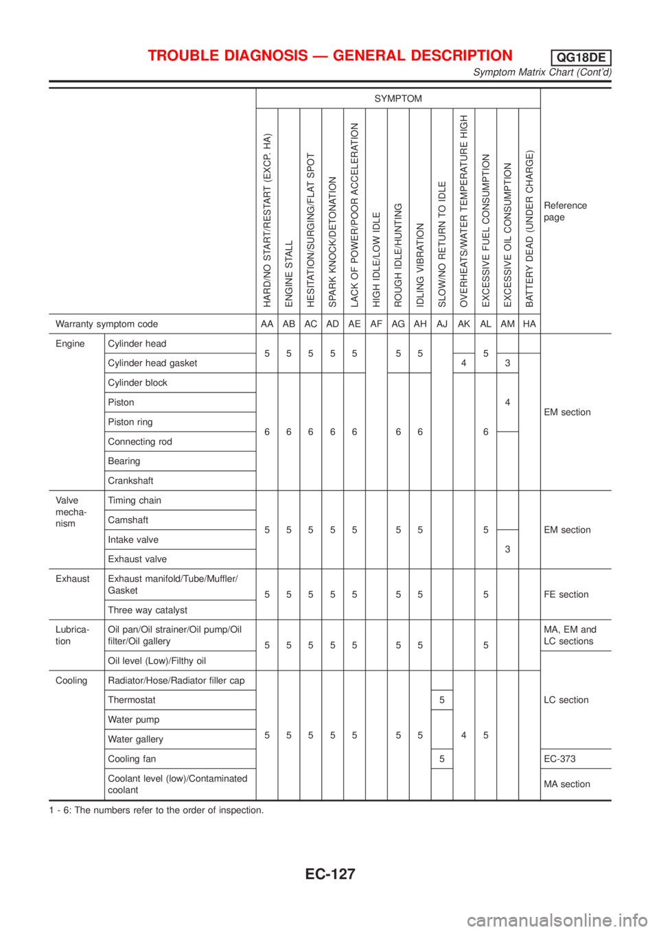
1 - 6: The numbers refer to the order of inspection.
TROUBLE DIAGNOSIS Ð GENERAL DESCRIPTIONQG18DE
Symptom Matrix Chart (Cont'd)
EC-127
Page 699 of 3051
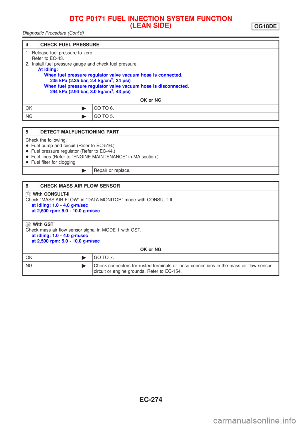
4 CHECK FUEL PRESSURE
1. Release fuel pressure to zero.
Refer to EC-43.
2. Install fuel pressure gauge and check fuel pressure.
At idling:
When fuel pressure regulator valve vacuum hose is connected.
235 kPa (2.35 bar, 2.4 kg/cm
2, 34 psi)
When fuel pressure regulator valve vacuum hose is disconnected.
294 kPa (2.94 bar, 3.0 kg/cm
2, 43 psi)
OK or NG
OK©GO TO 6.
NG©GO TO 5.
5 DETECT MALFUNCTIONING PART
Check the following.
+Fuel pump and circuit (Refer to EC-516.)
+Fuel pressure regulator (Refer to EC-44.)
+Fuel lines (Refer to ªENGINE MAINTENANCEº in MA section.)
+Fuel filter for clogging
©Repair or replace.
6 CHECK MASS AIR FLOW SENSOR
With CONSULT-II
Check ªMASS AIR FLOWº in ªDATA MONITORº mode with CONSULT-II.
at idling: 1.0 - 4.0 g´m/sec
at 2,500 rpm: 5.0 - 10.0 g´m/sec
With GST
Check mass air flow sensor signal in MODE 1 with GST.
at idling: 1.0 - 4.0 g´m/sec
at 2,500 rpm: 5.0 - 10.0 g´m/sec
OK or NG
OK©GO TO 7.
NG©Check connectors for rusted terminals or loose connections in the mass air flow sensor
circuit or engine grounds. Refer to EC-154.
DTC P0171 FUEL INJECTION SYSTEM FUNCTION
(LEAN SIDE)
QG18DE
Diagnostic Procedure (Cont'd)
EC-274
Page 714 of 3051
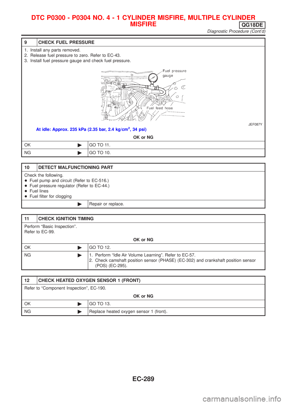
9 CHECK FUEL PRESSURE
1. Install any parts removed.
2. Release fuel pressure to zero. Refer to EC-43.
3. Install fuel pressure gauge and check fuel pressure.
JEF087Y
At idle: Approx. 235 kPa (2.35 bar, 2.4 kg/cm2, 34 psi)
OK or NG
OK©GO TO 11.
NG©GO TO 10.
10 DETECT MALFUNCTIONING PART
Check the following.
+Fuel pump and circuit (Refer to EC-516.)
+Fuel pressure regulator (Refer to EC-44.)
+Fuel lines
+Fuel filter for clogging
©Repair or replace.
11 CHECK IGNITION TIMING
Perform ªBasic Inspectionº.
Refer to EC-99.
OK or NG
OK©GO TO 12.
NG©1. Perform ªIdle Air Volume Learningº. Refer to EC-57.
2. Check camshaft position sensor (PHASE) (EC-302) and crankshaft position sensor
(POS) (EC-295).
12 CHECK HEATED OXYGEN SENSOR 1 (FRONT)
Refer to ªComponent Inspectionº, EC-190.
OK or NG
OK©GO TO 13.
NG©Replace heated oxygen sensor 1 (front).
DTC P0300 - P0304 NO.4-1CYLINDER MISFIRE, MULTIPLE CYLINDER
MISFIRE
QG18DE
Diagnostic Procedure (Cont'd)
EC-289
Page 1076 of 3051
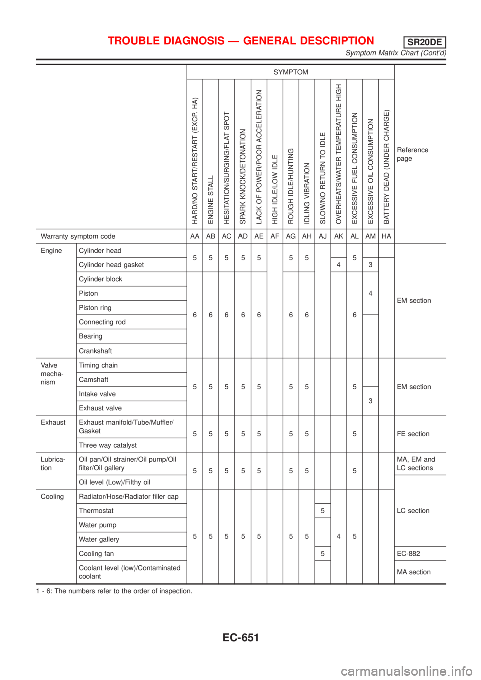
SYMPTOM
Reference
page
HARD/NO START/RESTART (EXCP. HA)
ENGINE STALL
HESITATION/SURGING/FLAT SPOT
SPARK KNOCK/DETONATION
LACK OF POWER/POOR ACCELERATION
HIGH IDLE/LOW IDLE
ROUGH IDLE/HUNTING
IDLING VIBRATION
SLOW/NO RETURN TO IDLE
OVERHEATS/WATER TEMPERATURE HIGH
EXCESSIVE FUEL CONSUMPTION
EXCESSIVE OIL CONSUMPTION
BATTERY DEAD (UNDER CHARGE)
Warranty symptom code AA AB AC AD AE AF AG AH AJ AK AL AM HA
Engine Cylinder head
55555 55 5
EM section Cylinder head gasket 4 3
Cylinder block
66666 66 64 Piston
Piston ring
Connecting rod
Bearing
Crankshaft
Valve
mecha-
nismTiming chain
55555 55 5 EMsection Camshaft
Intake valve
3
Exhaust valve
Exhaust Exhaust manifold/Tube/Muffler/
Gasket
55555 55 5 FEsection
Three way catalyst
Lubrica-
tionOil pan/Oil strainer/Oil pump/Oil
filter/Oil gallery
55555 55 5MA, EM and
LC sections
Oil level (Low)/Filthy oil
LC section Cooling Radiator/Hose/Radiator filler cap
55555 55 45 Thermostat 5
Water pump
Water gallery
Cooling fan 5 EC-882
Coolant level (low)/Contaminated
coolantMA section
1 - 6: The numbers refer to the order of inspection.
TROUBLE DIAGNOSIS Ð GENERAL DESCRIPTIONSR20DE
Symptom Matrix Chart (Cont'd)
EC-651
Page 1222 of 3051
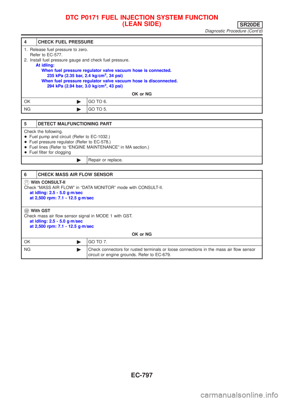
4 CHECK FUEL PRESSURE
1. Release fuel pressure to zero.
Refer to EC-577.
2. Install fuel pressure gauge and check fuel pressure.
At idling:
When fuel pressure regulator valve vacuum hose is connected.
235 kPa (2.35 bar, 2.4 kg/cm
2, 34 psi)
When fuel pressure regulator valve vacuum hose is disconnected.
294 kPa (2.94 bar, 3.0 kg/cm
2, 43 psi)
OK or NG
OK©GO TO 6.
NG©GO TO 5.
5 DETECT MALFUNCTIONING PART
Check the following.
+Fuel pump and circuit (Refer to EC-1032.)
+Fuel pressure regulator (Refer to EC-578.)
+Fuel lines (Refer to ªENGINE MAINTENANCEº in MA section.)
+Fuel filter for clogging
©Repair or replace.
6 CHECK MASS AIR FLOW SENSOR
With CONSULT-II
Check ªMASS AIR FLOWº in ªDATA MONITORº mode with CONSULT-II.
at idling: 2.5 - 5.0 g´m/sec
at 2,500 rpm: 7.1 - 12.5 g´m/sec
With GST
Check mass air flow sensor signal in MODE 1 with GST.
at idling: 2.5 - 5.0 g´m/sec
at 2,500 rpm: 7.1 - 12.5 g´m/sec
OK or NG
OK©GO TO 7.
NG©Check connectors for rusted terminals or loose connections in the mass air flow sensor
circuit or engine grounds. Refer to EC-679.
DTC P0171 FUEL INJECTION SYSTEM FUNCTION
(LEAN SIDE)
SR20DE
Diagnostic Procedure (Cont'd)
EC-797