2001 NISSAN ALMERA TINO parking brake
[x] Cancel search: parking brakePage 11 of 3051

SMA146B
Checking CVT FluidNLAT02431. Check for fluid leakage.
SAT282K
2. Check fluid level.
Fluid level should be check using ªHOTº range on A/T fluid
level gauge at fluid temperatures of 50 to 80ÉC (122 to 176ÉF)
after vehicle has been driven approximately 10 minutes in
urban areas after engine is warmed up. But it can be checked
at fluid temperatures of 30 to 50ÉC (86 to 122ÉF) using ªCOLDº
range on A/T fluid level gauge for reference after engine is
warmed up and before driving. However, fluid level must be
rechecked using ªHOTº range.
a. Park vehicle on level surface and set parking brake.
b. Start engine and then move selector lever through reach gear
range, ending in ªPº.
c. Check fluid level with engine idling.
d. Remove A/T fluid level gauge and wipe it clean with lint-free
paper.
e. Re-insert A/T fluid level gauge into charging pipe as far as it
will go.
f. Remove A/T fluid level gauge and note reading. If level is at
low side of either range, add fluid through the speedometer
cable hole.
Use genuine NISSAN CVT fluid (NS-1) or exact equivalent.
CAUTION:
Do not overfill.
CAUTION:
SMA051D
Firmly fix the A/T fluid level gauge using a lip attached to the
fluid charging pipe.
CVT FLUID
Checking CVT Fluid
AT-10
Page 53 of 3051
SAT513G
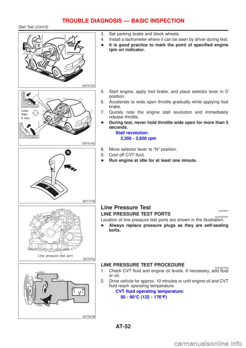
3. Set parking brake and block wheels.
4. Install a tachometer where it can be seen by driver during test.
+It is good practice to mark the point of specified engine
rpm on indicator.
SAT514G
5. Start engine, apply foot brake, and place selector lever in D
position.
6. Accelerate to wide open throttle gradually while applying foot
brake.
7. Quickly note the engine stall revolution and immediately
release throttle.
+During test, never hold throttle wide open for more than 5
seconds.
Stall revolution:
2,350 - 2,850 rpm
SAT771B
8. Move selector lever to ªNº position.
9. Cool off CVT fluid.
+Run engine at idle for at least one minute.
SAT670J
Line Pressure TestNLAT0027LINE PRESSURE TEST PORTSNLAT0027S01Location of line pressure test ports are shown in the illustration.
+Always replace pressure plugs as they are self-sealing
bolts.
SAT647B
LINE PRESSURE TEST PROCEDURENLAT0027S021. Check CVT fluid and engine oil levels. If necessary, add fluid
or oil.
2. Drive vehicle for approx. 10 minutes or until engine oil and CVT
fluid reach operating temperature.
CVT fluid operating temperature:
50 - 80ÉC (122 - 176ÉF)
TROUBLE DIAGNOSIS Ð BASIC INSPECTION
Stall Test (Cont'd)
AT-52
Page 54 of 3051
3. Install pressure gauge to corresponding line pressure port.
SAT513G
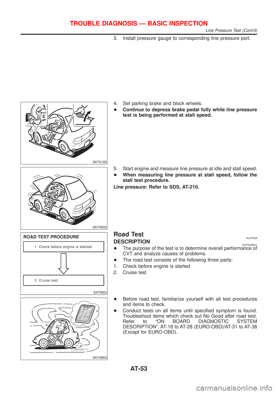
4. Set parking brake and block wheels.
+Continue to depress brake pedal fully while line pressure
test is being performed at stall speed.
SAT493G
5. Start engine and measure line pressure at idle and stall speed.
+When measuring line pressure at stall speed, follow the
stall test procedure.
Line pressure: Refer to SDS, AT-210.
SAT692J
Road TestNLAT0028DESCRIPTIONNLAT0028S01+The purpose of the test is to determine overall performance of
CVT and analyze causes of problems.
+The road test consists of the following three parts:
1. Check before engine is started
2. Cruise test
SAT496G
+Before road test, familiarize yourself with all test procedures
and items to check.
+Conduct tests on all items until specified symptom is found.
Troubleshoot items which check out No Good after road test.
Refer to ªON BOARD DIAGNOSTIC SYSTEM
DESCRIPTIONº, AT-18 to AT-28 (EURO-OBD)/AT-31 to AT-38
(Except for EURO-OBD).
TROUBLE DIAGNOSIS Ð BASIC INSPECTION
Line Pressure Test (Cont'd)
AT-53
Page 196 of 3051
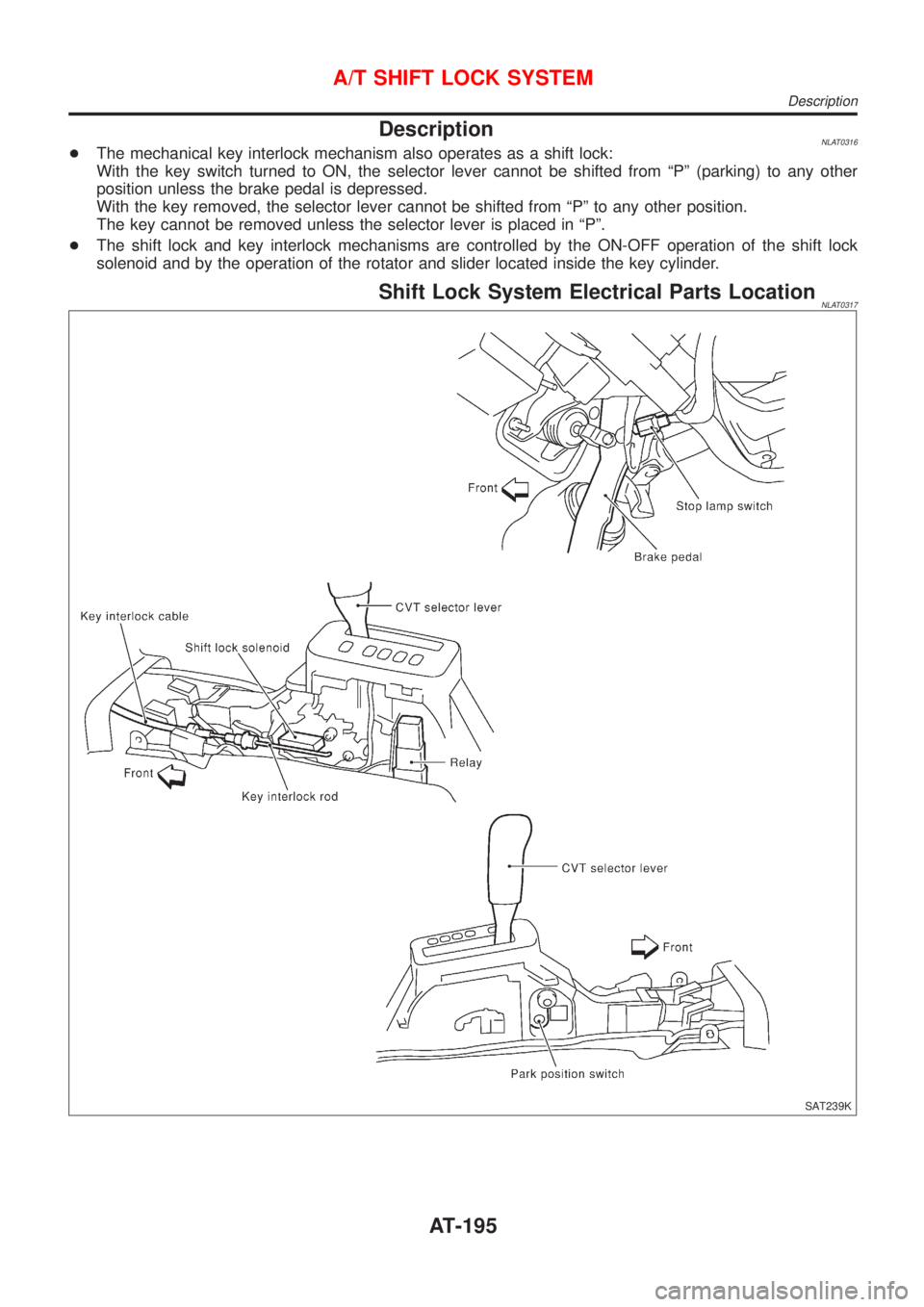
DescriptionNLAT0316+The mechanical key interlock mechanism also operates as a shift lock:
With the key switch turned to ON, the selector lever cannot be shifted from ªPº (parking) to any other
position unless the brake pedal is depressed.
With the key removed, the selector lever cannot be shifted from ªPº to any other position.
The key cannot be removed unless the selector lever is placed in ªPº.
+The shift lock and key interlock mechanisms are controlled by the ON-OFF operation of the shift lock
solenoid and by the operation of the rotator and slider located inside the key cylinder.
Shift Lock System Electrical Parts LocationNLAT0317
SAT239K
A/T SHIFT LOCK SYSTEM
Description
AT-195
Page 208 of 3051
SAT266K
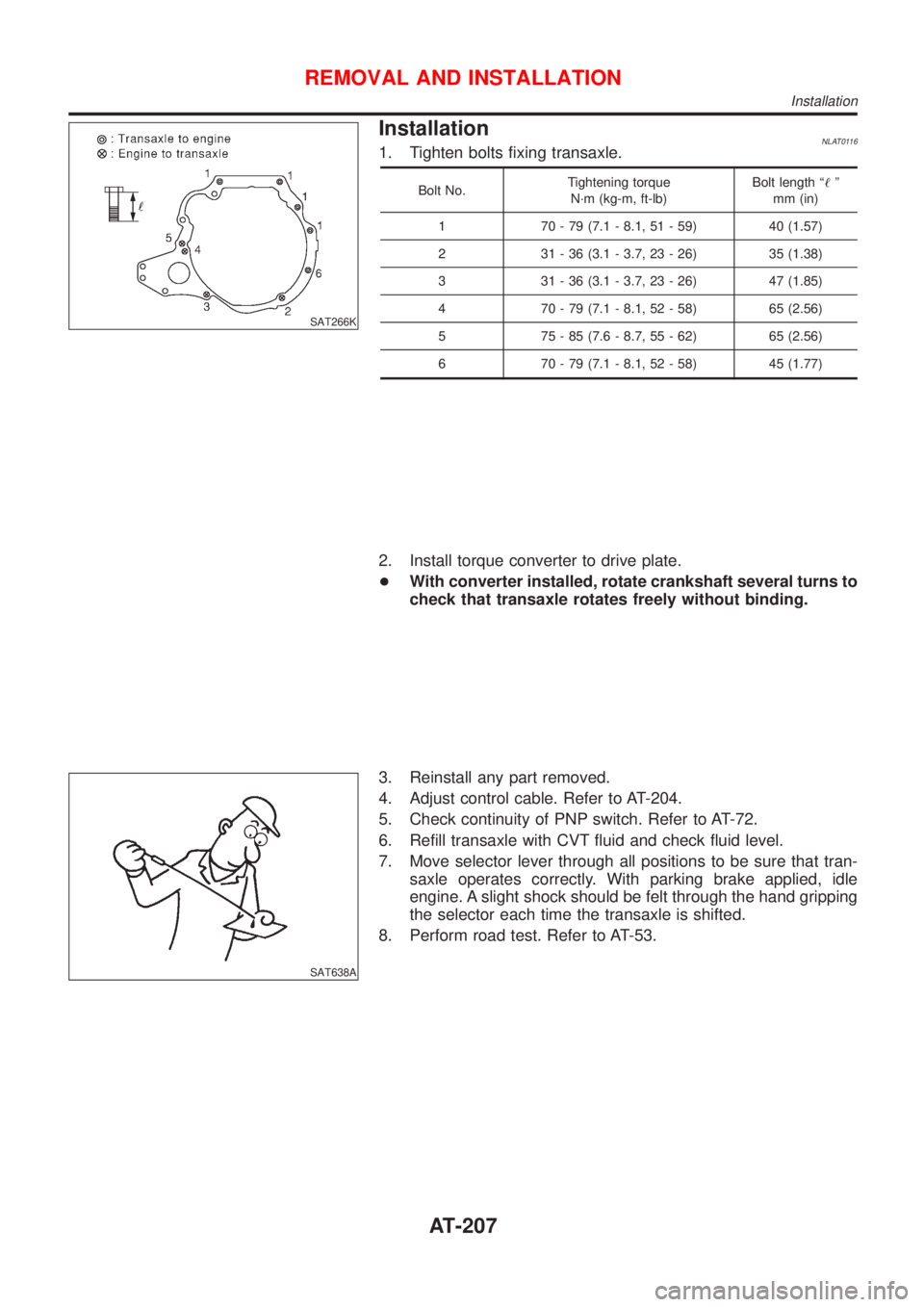
InstallationNLAT01161. Tighten bolts fixing transaxle.
Bolt No.Tightening torque
N´m (kg-m, ft-lb)Bolt length ª!º
mm (in)
1 70 - 79 (7.1 - 8.1, 51 - 59) 40 (1.57)
2 31 - 36 (3.1 - 3.7, 23 - 26) 35 (1.38)
3 31 - 36 (3.1 - 3.7, 23 - 26) 47 (1.85)
4 70 - 79 (7.1 - 8.1, 52 - 58) 65 (2.56)
5 75 - 85 (7.6 - 8.7, 55 - 62) 65 (2.56)
6 70 - 79 (7.1 - 8.1, 52 - 58) 45 (1.77)
2. Install torque converter to drive plate.
+With converter installed, rotate crankshaft several turns to
check that transaxle rotates freely without binding.
SAT638A
3. Reinstall any part removed.
4. Adjust control cable. Refer to AT-204.
5. Check continuity of PNP switch. Refer to AT-72.
6. Refill transaxle with CVT fluid and check fluid level.
7. Move selector lever through all positions to be sure that tran-
saxle operates correctly. With parking brake applied, idle
engine. A slight shock should be felt through the hand gripping
the selector each time the transaxle is shifted.
8. Perform road test. Refer to AT-53.
REMOVAL AND INSTALLATION
Installation
AT-207
Page 239 of 3051
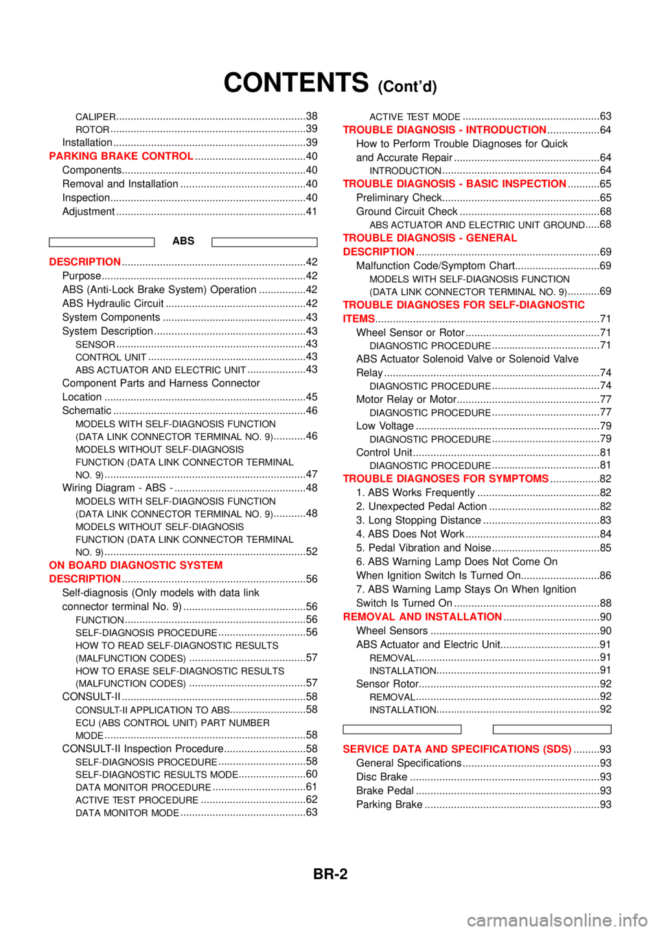
CALIPER.................................................................38
ROTOR...................................................................39
Installation ..................................................................39
PARKING BRAKE CONTROL......................................40
Components...............................................................40
Removal and Installation ...........................................40
Inspection...................................................................40
Adjustment .................................................................41
ABS
DESCRIPTION...............................................................42
Purpose......................................................................42
ABS (Anti-Lock Brake System) Operation ................42
ABS Hydraulic Circuit ................................................42
System Components .................................................43
System Description ....................................................43
SENSOR.................................................................43
CONTROL UNIT......................................................43
ABS ACTUATOR AND ELECTRIC UNIT....................43
Component Parts and Harness Connector
Location .....................................................................45
Schematic ..................................................................46
MODELS WITH SELF-DIAGNOSIS FUNCTION
(DATA LINK CONNECTOR TERMINAL NO. 9)
...........46
MODELS WITHOUT SELF-DIAGNOSIS
FUNCTION (DATA LINK CONNECTOR TERMINAL
NO. 9)
.....................................................................47
Wiring Diagram - ABS - .............................................48
MODELS WITH SELF-DIAGNOSIS FUNCTION
(DATA LINK CONNECTOR TERMINAL NO. 9)
...........48
MODELS WITHOUT SELF-DIAGNOSIS
FUNCTION (DATA LINK CONNECTOR TERMINAL
NO. 9)
.....................................................................52
ON BOARD DIAGNOSTIC SYSTEM
DESCRIPTION...............................................................56
Self-diagnosis (Only models with data link
connector terminal No. 9) ..........................................56
FUNCTION..............................................................56
SELF-DIAGNOSIS PROCEDURE..............................56
HOW TO READ SELF-DIAGNOSTIC RESULTS
(MALFUNCTION CODES)
........................................57
HOW TO ERASE SELF-DIAGNOSTIC RESULTS
(MALFUNCTION CODES)
........................................57
CONSULT-II ...............................................................58
CONSULT-II APPLICATION TO ABS..........................58
ECU (ABS CONTROL UNIT) PART NUMBER
MODE
.....................................................................58
CONSULT-II Inspection Procedure............................58
SELF-DIAGNOSIS PROCEDURE..............................58
SELF-DIAGNOSTIC RESULTS MODE.......................60
DATA MONITOR PROCEDURE................................61
ACTIVE TEST PROCEDURE....................................62
DATA MONITOR MODE...........................................63
ACTIVE TEST MODE...............................................63
TROUBLE DIAGNOSIS - INTRODUCTION..................64
How to Perform Trouble Diagnoses for Quick
and Accurate Repair ..................................................64
INTRODUCTION......................................................64
TROUBLE DIAGNOSIS - BASIC INSPECTION...........65
Preliminary Check......................................................65
Ground Circuit Check ................................................68
ABS ACTUATOR AND ELECTRIC UNIT GROUND.....68
TROUBLE DIAGNOSIS - GENERAL
DESCRIPTION...............................................................69
Malfunction Code/Symptom Chart.............................69
MODELS WITH SELF-DIAGNOSIS FUNCTION
(DATA LINK CONNECTOR TERMINAL NO. 9)
...........69
TROUBLE DIAGNOSES FOR SELF-DIAGNOSTIC
ITEMS.............................................................................71
Wheel Sensor or Rotor ..............................................71
DIAGNOSTIC PROCEDURE.....................................71
ABS Actuator Solenoid Valve or Solenoid Valve
Relay ..........................................................................74
DIAGNOSTIC PROCEDURE.....................................74
Motor Relay or Motor.................................................77
DIAGNOSTIC PROCEDURE.....................................77
Low Voltage ...............................................................79
DIAGNOSTIC PROCEDURE.....................................79
Control Unit ................................................................81
DIAGNOSTIC PROCEDURE.....................................81
TROUBLE DIAGNOSES FOR SYMPTOMS.................82
1. ABS Works Frequently ..........................................82
2. Unexpected Pedal Action ......................................82
3. Long Stopping Distance ........................................83
4. ABS Does Not Work ..............................................84
5. Pedal Vibration and Noise.....................................85
6. ABS Warning Lamp Does Not Come On
When Ignition Switch Is Turned On...........................86
7. ABS Warning Lamp Stays On When Ignition
Switch Is Turned On ..................................................88
REMOVAL AND INSTALLATION.................................90
Wheel Sensors ..........................................................90
ABS Actuator and Electric Unit..................................91
REMOVAL...............................................................91
INSTALLATION........................................................91
Sensor Rotor..............................................................92
REMOVAL...............................................................92
INSTALLATION........................................................92
SERVICE DATA AND SPECIFICATIONS (SDS).........93
General Specifications ...............................................93
Disc Brake .................................................................93
Brake Pedal ...............................................................93
Parking Brake ............................................................93
CONTENTS(Cont’d)
BR-2
Page 244 of 3051

NBR376
Checking Brake Fluid LevelNLBR0006+Check fluid level in reservoir tank. It should be between Max
and Min lines on reservoir tank.
+If fluid level is extremely low, check brake system for leaks.
+Release parking brake lever and see if brake warning lamp
goes off. If not, check brake system for leaks.
SBR389C
Checking Brake LineNLBR0007CAUTION:
If leakage occurs around joints, retighten or, if necessary,
replace damaged parts.
1. Check brake lines (tubes and hoses) for cracks, deterioration
or other damage. Replace any damaged parts.
2. Check for oil leakage by fully depressing brake pedal while
engine is running.
SBR419C
Changing Brake FluidNLBR0008CAUTION:
+Refill with new brake fluid“DOT 4”.
+Always keep fluid level higher than minimum line on res-
ervoir tank.
+Never reuse drained brake fluid.
+Be careful not to splash brake fluid on painted areas; it
may cause paint damage. If brake fluid is splashed on
painted areas, wash it away with water immediately.
1. Clean inside of reservoir tank, and refill with new brake fluid.
2. Connect a vinyl tube to each air bleeder valve.
3. Drain brake fluid from each air bleeder valve by depressing
brake pedal while keeping reservoir level higher than minimum
line by adding new brake fluid.
4. Repeat until new brake fluid comes out of each air bleeder
valve.
Use same procedure as in bleeding hydraulic system to refill
brake fluid. Refer to“Bleeding Brake System”, BR-8 and“Air
Bleeding Procedure”, CL-10.
Brake Burnishing ProcedureNLBR0036Burnish the brake contact surfaces according to the following pro-
cedure after refinishing or replacing rotors, after replacing pads, or
if a soft pedal occurs at very low mileage.
CAUTION:
Only perform this procedure under safe road and traffic con-
ditions. Use extreme caution.
1. Drive the vehicle on a straight smooth road at 50 km/h (31
MPH).
2. Use medium brake pedal/foot effort to bring the vehicle to a
complete stop from 50 km/h (31 MPH). Adjust brake pedal/foot
ON-VEHICLE SERVICE
Checking Brake Fluid Level
BR-7
Page 266 of 3051
+It is not necessary to remove connecting bolt except for
disassembly or replacement of caliper assembly. In this
case, suspend cylinder body with wire so as not to stretch
brake hose.
+Burnish the brake contact surfaces after refinishing or
replacing rotors, after replacing pads, or if a soft pedal
occurs at very low mileage.
Refer to“Brake Burnishing Procedure”,“ON-VEHICLE
SERVICE”, BR-7.
SBR764E
SBR916C
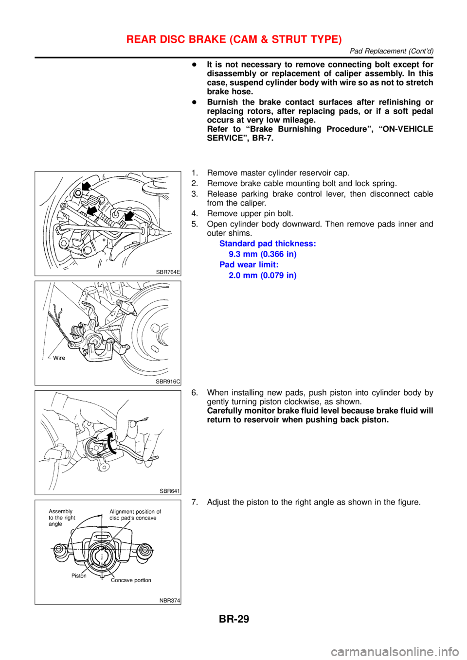
1. Remove master cylinder reservoir cap.
2. Remove brake cable mounting bolt and lock spring.
3. Release parking brake control lever, then disconnect cable
from the caliper.
4. Remove upper pin bolt.
5. Open cylinder body downward. Then remove pads inner and
outer shims.
Standard pad thickness:
9.3 mm (0.366 in)
Pad wear limit:
2.0 mm (0.079 in)
SBR641
6. When installing new pads, push piston into cylinder body by
gently turning piston clockwise, as shown.
Carefully monitor brake fluid level because brake fluid will
return to reservoir when pushing back piston.
NBR374
7. Adjust the piston to the right angle as shown in the figure.
REAR DISC BRAKE (CAM & STRUT TYPE)
Pad Replacement (Cont’d)
BR-29