2001 NISSAN ALMERA TINO brake fluid
[x] Cancel search: brake fluidPage 11 of 3051

SMA146B
Checking CVT FluidNLAT02431. Check for fluid leakage.
SAT282K
2. Check fluid level.
Fluid level should be check using ªHOTº range on A/T fluid
level gauge at fluid temperatures of 50 to 80ÉC (122 to 176ÉF)
after vehicle has been driven approximately 10 minutes in
urban areas after engine is warmed up. But it can be checked
at fluid temperatures of 30 to 50ÉC (86 to 122ÉF) using ªCOLDº
range on A/T fluid level gauge for reference after engine is
warmed up and before driving. However, fluid level must be
rechecked using ªHOTº range.
a. Park vehicle on level surface and set parking brake.
b. Start engine and then move selector lever through reach gear
range, ending in ªPº.
c. Check fluid level with engine idling.
d. Remove A/T fluid level gauge and wipe it clean with lint-free
paper.
e. Re-insert A/T fluid level gauge into charging pipe as far as it
will go.
f. Remove A/T fluid level gauge and note reading. If level is at
low side of either range, add fluid through the speedometer
cable hole.
Use genuine NISSAN CVT fluid (NS-1) or exact equivalent.
CAUTION:
Do not overfill.
CAUTION:
SMA051D
Firmly fix the A/T fluid level gauge using a lip attached to the
fluid charging pipe.
CVT FLUID
Checking CVT Fluid
AT-10
Page 18 of 3051
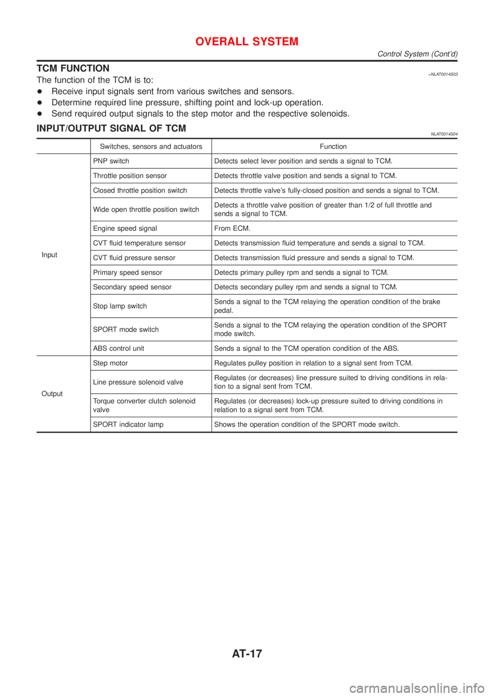
TCM FUNCTION=NLAT0014S03The function of the TCM is to:
+Receive input signals sent from various switches and sensors.
+Determine required line pressure, shifting point and lock-up operation.
+Send required output signals to the step motor and the respective solenoids.
INPUT/OUTPUT SIGNAL OF TCMNLAT0014S04
Switches, sensors and actuators Function
InputPNP switch Detects select lever position and sends a signal to TCM.
Throttle position sensor Detects throttle valve position and sends a signal to TCM.
Closed throttle position switch Detects throttle valve's fully-closed position and sends a signal to TCM.
Wide open throttle position switchDetects a throttle valve position of greater than 1/2 of full throttle and
sends a signal to TCM.
Engine speed signal From ECM.
CVT fluid temperature sensor Detects transmission fluid temperature and sends a signal to TCM.
CVT fluid pressure sensor Detects transmission fluid pressure and sends a signal to TCM.
Primary speed sensor Detects primary pulley rpm and sends a signal to TCM.
Secondary speed sensor Detects secondary pulley rpm and sends a signal to TCM.
Stop lamp switchSends a signal to the TCM relaying the operation condition of the brake
pedal.
SPORT mode switchSends a signal to the TCM relaying the operation condition of the SPORT
mode switch.
ABS control unit Sends a signal to the TCM operation condition of the ABS.
OutputStep motor Regulates pulley position in relation to a signal sent from TCM.
Line pressure solenoid valveRegulates (or decreases) line pressure suited to driving conditions in rela-
tion to a signal sent from TCM.
Torque converter clutch solenoid
valveRegulates (or decreases) lock-up pressure suited to driving conditions in
relation to a signal sent from TCM.
SPORT indicator lamp Shows the operation condition of the SPORT mode switch.
OVERALL SYSTEM
Control System (Cont'd)
AT-17
Page 35 of 3051
![NISSAN ALMERA TINO 2001 Service Repair Manual Item DisplayMonitor item
Description Remarks
TCM input
signalsMain sig-
nals
Line pressure sensor LINE PRES
SEN [V] X Ð+CVT fluid pressure sen-
sor signal voltage is
displayed.Ð
Primary pulley speed NISSAN ALMERA TINO 2001 Service Repair Manual Item DisplayMonitor item
Description Remarks
TCM input
signalsMain sig-
nals
Line pressure sensor LINE PRES
SEN [V] X Ð+CVT fluid pressure sen-
sor signal voltage is
displayed.Ð
Primary pulley speed](/manual-img/5/57352/w960_57352-34.png)
Item DisplayMonitor item
Description Remarks
TCM input
signalsMain sig-
nals
Line pressure sensor LINE PRES
SEN [V] X Ð+CVT fluid pressure sen-
sor signal voltage is
displayed.Ð
Primary pulley speed sen-
sorI/P PULLY SPD
[rpm]
XX+Primary pulley speed
computed from signal
of primary pulley speed
sensor is displayed.
Secondary pulley speed
sensorO/P PULLY SPD
[rpm]
ÐÐ+Secondary pulley speed
computed from signal
of secondary speed
sensor is displayed.Ð
Stop lamp switch BRAKE SW
[ON/OFF] X Ð+ON/OFF position signal
of stop lamp switch is
displayed.Ð
ABS signal ABS SIGNAL
[ON/OFF]
XÐ+ABS operation signal
(ON/OFF) from ABS
control unit is dis-
played.Ð
CVT ratio CVT RATIO [Ð]
ÐX+Real CVT ratio oper-
ated TCM is displayed.Ð
Step PLY CONT
STEP [step]ÐX+Step motor position is
displayed.Ð
X: Applicable
Ð: Not applicable
SAT250K
HOW TO ERASE SELF-DIAGNOSTIC RESULTS
(
WITH CONSULT-II)NLAT0245S091. If the ignition switch stays ªONº after repair work, be sure to
turn ignition switch ªOFFº once. Wait for at least 3 seconds and
then turn it ªONº again.
2. Turn CONSULT-II ªONº, and touch ªCVTº.
SAT252K
3. Touch ªSELF-DIAG RESULTSº.
ON BOARD DIAGNOSTIC SYSTEM
DESCRIPTION
EXCEPT FOR EURO-OBD
CONSULT-II (Cont'd)
AT-34
Page 44 of 3051
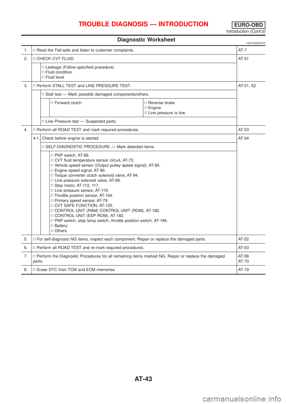
Diagnostic Worksheet=NLAT0023S0102
1.NRead the Fail-safe and listen to customer complaints. AT-7
2.NCHECK CVT FLUIDAT-51
NLeakage (Follow specified procedure)
NFluid condition
NFluid level
3.NPerform STALL TEST and LINE PRESSURE TEST. AT-51, 52
NStall test Ð Mark possible damaged components/others.
NForward clutchNReverse brake
NEngine
NLine pressure is low.
NLine Pressure test Ð Suspected parts:
4.NPerform all ROAD TEST and mark required procedures. AT-53
4-1. Check before engine is started.AT-54
NSELF-DIAGNOSTIC PROCEDURE Ð Mark detected items.
NPNP switch, AT-66.
NCVT fluid temperature sensor circuit, AT-73.
NVehicle speed sensor (Output pulley speed signal), AT-84.
NEngine speed signal, AT-90.
NTorque converter clutch solenoid valve, AT-94.
NLine pressure solenoid valve, AT-99.
NStep motor, AT-112, 117.
NLine pressure sensor, AT-119.
NThrottle position sensor, AT-104.
NPrimary speed sensor, AT-79.
NCVT SAFE FUNCTION, AT-125.
NCONTROL UNIT (RAM) CONTROL UNIT (ROM), AT-180.
NCONTROL UNIT (EEP ROM), AT-182.
NPNP switch, stop lamp switch, throttle position switch, AT-184.
NBattery
NOthers
5.NFor self-diagnosis NG items, inspect each component. Repair or replace the damaged parts. AT-22
6.NPerform all ROAD TEST and re-mark required procedures. AT-53
7.NPerform the Diagnostic Procedures for all remaining items marked NG. Repair or replace the damaged
parts.AT-58
AT-70
8.NErase DTC from TCM and ECM memories. AT-19
TROUBLE DIAGNOSIS Ð INTRODUCTIONEURO-OBD
Introduction (Cont'd)
AT-43
Page 49 of 3051
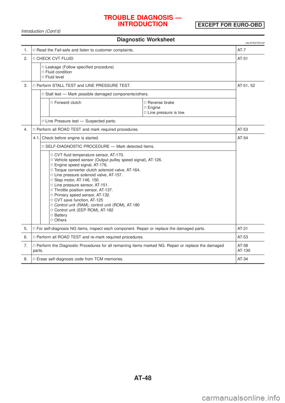
Diagnostic Worksheet=NLAT0247S0102
1.NRead the Fail-safe and listen to customer complaints. AT-7
2.NCHECK CVT FLUIDAT-51
NLeakage (Follow specified procedure)
NFluid condition
NFluid level
3.NPerform STALL TEST and LINE PRESSURE TEST. AT-51, 52
NStall test Ð Mark possible damaged components/others.
NForward clutchNReverse brake
NEngine
NLine pressure is low.
NLine Pressure test Ð Suspected parts:
4.NPerform all ROAD TEST and mark required procedures. AT-53
4-1. Check before engine is started.AT-54
NSELF-DIAGNOSTIC PROCEDURE Ð Mark detected items.
NCVT fluid temperature sensor, AT-170.
NVehicle speed sensor (Output pulley speed signal), AT-126.
NEngine speed signal, AT-176.
NTorque converter clutch solenoid valve, AT-164.
NLine pressure solenoid valve, AT-157.
NStep motor, AT-146, 150.
NLine pressure sensor, AT-151.
NThrottle position sensor, AT-137.
NPrimary speed sensor, AT-132.
NCVT save function, AT-125
NControl unit (RAM), control unit (ROM), AT-180
NControl unit (EEP ROM), AT-182
NBattery
NOthers
5.NFor self-diagnosis NG items, inspect each component. Repair or replace the damaged parts. AT-31
6.NPerform all ROAD TEST and re-mark required procedures. AT-53
7.NPerform the Diagnostic Procedures for all remaining items marked NG. Repair or replace the damaged
parts.AT-58
AT-130
8.NErase self-diagnosis code from TCM memories. AT-34
TROUBLE DIAGNOSIS Ð
INTRODUCTION
EXCEPT FOR EURO-OBD
Introduction (Cont'd)
AT-48
Page 52 of 3051
SAT767B
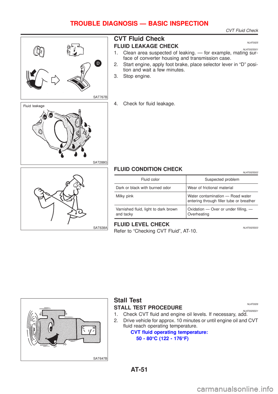
CVT Fluid CheckNLAT0025FLUID LEAKAGE CHECKNLAT0025S011. Clean area suspected of leaking. Ð for example, mating sur-
face of converter housing and transmission case.
2. Start engine, apply foot brake, place selector lever in ªDº posi-
tion and wait a few minutes.
3. Stop engine.
SAT288G
4. Check for fluid leakage.
SAT638A
FLUID CONDITION CHECKNLAT0025S02
Fluid color Suspected problem
Dark or black with burned odor Wear of frictional material
Milky pink Water contamination Ð Road water
entering through filler tube or breather
Varnished fluid, light to dark brown
and tackyOxidation Ð Over or under filling, Ð
Overheating
FLUID LEVEL CHECKNLAT0025S03Refer to ªChecking CVT Fluidº, AT-10.
SAT647B
Stall TestNLAT0026STALL TEST PROCEDURENLAT0026S011. Check CVT fluid and engine oil levels. If necessary, add.
2. Drive vehicle for approx. 10 minutes or until engine oil and CVT
fluid reach operating temperature.
CVT fluid operating temperature:
50 - 80ÉC (122 - 176ÉF)
TROUBLE DIAGNOSIS Ð BASIC INSPECTION
CVT Fluid Check
AT-51
Page 53 of 3051
SAT513G
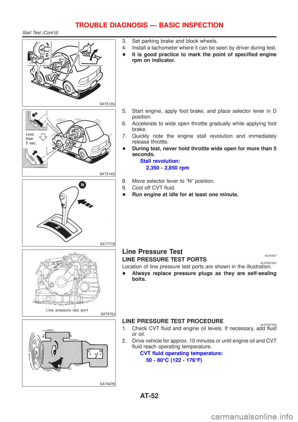
3. Set parking brake and block wheels.
4. Install a tachometer where it can be seen by driver during test.
+It is good practice to mark the point of specified engine
rpm on indicator.
SAT514G
5. Start engine, apply foot brake, and place selector lever in D
position.
6. Accelerate to wide open throttle gradually while applying foot
brake.
7. Quickly note the engine stall revolution and immediately
release throttle.
+During test, never hold throttle wide open for more than 5
seconds.
Stall revolution:
2,350 - 2,850 rpm
SAT771B
8. Move selector lever to ªNº position.
9. Cool off CVT fluid.
+Run engine at idle for at least one minute.
SAT670J
Line Pressure TestNLAT0027LINE PRESSURE TEST PORTSNLAT0027S01Location of line pressure test ports are shown in the illustration.
+Always replace pressure plugs as they are self-sealing
bolts.
SAT647B
LINE PRESSURE TEST PROCEDURENLAT0027S021. Check CVT fluid and engine oil levels. If necessary, add fluid
or oil.
2. Drive vehicle for approx. 10 minutes or until engine oil and CVT
fluid reach operating temperature.
CVT fluid operating temperature:
50 - 80ÉC (122 - 176ÉF)
TROUBLE DIAGNOSIS Ð BASIC INSPECTION
Stall Test (Cont'd)
AT-52
Page 208 of 3051
SAT266K
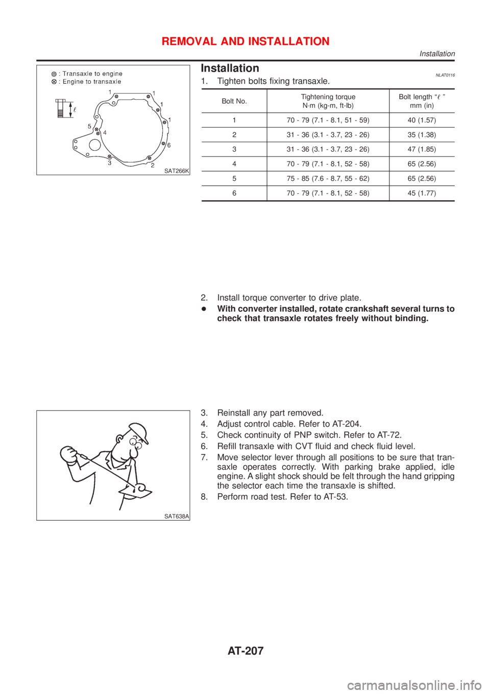
InstallationNLAT01161. Tighten bolts fixing transaxle.
Bolt No.Tightening torque
N´m (kg-m, ft-lb)Bolt length ª!º
mm (in)
1 70 - 79 (7.1 - 8.1, 51 - 59) 40 (1.57)
2 31 - 36 (3.1 - 3.7, 23 - 26) 35 (1.38)
3 31 - 36 (3.1 - 3.7, 23 - 26) 47 (1.85)
4 70 - 79 (7.1 - 8.1, 52 - 58) 65 (2.56)
5 75 - 85 (7.6 - 8.7, 55 - 62) 65 (2.56)
6 70 - 79 (7.1 - 8.1, 52 - 58) 45 (1.77)
2. Install torque converter to drive plate.
+With converter installed, rotate crankshaft several turns to
check that transaxle rotates freely without binding.
SAT638A
3. Reinstall any part removed.
4. Adjust control cable. Refer to AT-204.
5. Check continuity of PNP switch. Refer to AT-72.
6. Refill transaxle with CVT fluid and check fluid level.
7. Move selector lever through all positions to be sure that tran-
saxle operates correctly. With parking brake applied, idle
engine. A slight shock should be felt through the hand gripping
the selector each time the transaxle is shifted.
8. Perform road test. Refer to AT-53.
REMOVAL AND INSTALLATION
Installation
AT-207