Page 319 of 3051

1. ABS Works FrequentlyNLBR0104
1 CHECK BRAKE FLUID PRESSURE
Check brake fluid pressure distribution.
Is brake fluid pressure distribution normal?
Ye s©GO TO 2.
No©Perform Preliminary Check. Refer to BR-65.
2 CHECK WHEEL SENSOR
1. Check wheel sensor connector for terminal damage or loose connections.
2. Perform wheel sensor mechanical check.
Refer to ªWheel Sensor or Rotorº, BR-71.
Are wheel sensors functioning properly?
Ye s©GO TO 3.
No©Repair.
3 CHECK FRONT AXLE
Check front and rear axles for excessive looseness. Refer to AX section, ªFront Wheel Bearingº, ªON-VEHICLE SERVICEº
and ªRear Wheel Bearingº, ªON-VEHICLE SERVICEº.
Is front axle installed properly?
Ye s©Go to ª3. CHECK WARNING LAMP INDICATIONº in ª2. Unexpected Pedal Actionº,
BR-82.
No©Repair.
2. Unexpected Pedal ActionNLBR0105
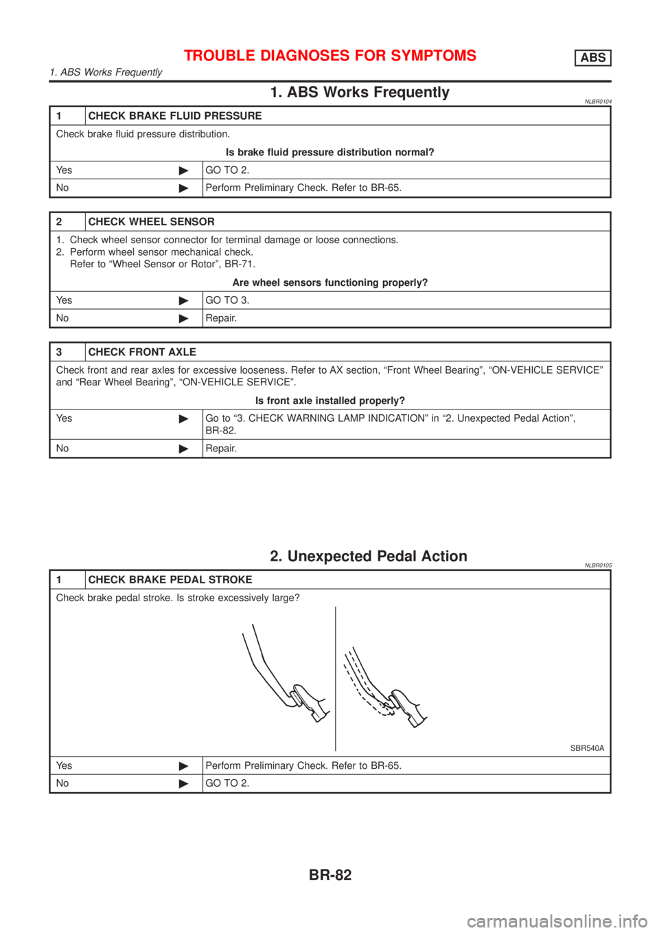
1 CHECK BRAKE PEDAL STROKE
Check brake pedal stroke. Is stroke excessively large?
SBR540A
Ye s©Perform Preliminary Check. Refer to BR-65.
No©GO TO 2.
TROUBLE DIAGNOSES FOR SYMPTOMSABS
1. ABS Works Frequently
BR-82
Page 328 of 3051
ABS Actuator and Electric UnitNLBR0111S10
SBR630E
REMOVALNLBR0111S10011. Disconnect battery cable.
2. Drain brake fluid.
3. Remove mounting bracket fixing bolts and nuts.
4. Disconnect connector, brake pipes and remove fixing nuts.
INSTALLATIONNLBR0111S1002CAUTION:
After installation, refill brake fluid. Then bleed air.
1. Connect brake pipes temporarily.
2. Tighten fixing bolts and nuts.
3. Tighten brake pipes.
4. Connect connector and battery cable.
REMOVAL AND INSTALLATIONABS
ABS Actuator and Electric Unit
BR-91
Page 330 of 3051

General SpecificationsNLBR0077Unit: mm (in)
EngineQG18DE, SR20DE YD22DDTi
Front BrakeBrake model CL25VCG
Cylinder bore diameter 57.2 (2.2529)
Pad
Length×width×thickness110.6×54.2×11.0 (4.35×2.13×0.433)
Rotor outer
diameter×thickness280×28 (11.02×1.10)
Rear BrakeBrake model CL11HDG (disc brake)
Cylinder bore diam-
eterCam & Strut type 38 (1.496)
Ball & Ramp type 38.2 (1.504)
Pad
Length×width×thickness79.8×38.5×9.3 (3.142×1.516×0.37)
Rotor outer diameter×thickness 278×10 (10.94×0.39)
Master cylinder Cylinder bore diameter 23.81 (15/16)
Brake boosterBooster model S255 M215T S255
DiaphragmPrimary 255 (10.04) 230 (9.06) 255 (10.04)
Secondary—205 (8.07)—
Specified brake fluidDOT 4
Disc BrakeNLBR0078Unit: mm (in)
Brake modelCL25VCG CL11HDG
Pad wear limit Minimum thickness 2.0 (0.078) 2.0 (0.079)
Rotor repair limitMaximum runout 0.07 (0.0028) 0.07 (0.0028)
Minimum thickness 26.0 (1.024) 9 (0.35)
Brake PedalNLBR0079Unit: mm (in)
Free height“H”*LHDM/T 154.8 - 164.8 (6.09 - 6.49)
CVT 164 - 174 (6.46 - 6.85)
RHDM/T 154.8 - 164.8 (6.09 - 6.49)
CVT 164 - 174 (6.46 - 6.85)
Clearance“C”between pedal stopper and threaded end of stop lamp switch or brake switch 0.75 - 2.00 (0.0295 - 0.0787)
*: Measured from surface of dash panel to surface of pedal pad
Parking BrakeNLBR0080
TypeCenter lever
Number of notches
[under force of 196 N (20 kg, 44 lb)]5-6
Number of notches
when warning lamp switch comes on1
SERVICE DATA AND SPECIFICATIONS (SDS)
General Specifications
BR-93
Page 403 of 3051
SBR820BA
PrecautionsNLCL0001+Recommended fluid is brake fluid ªDOT 4º. Refer to
MA-20, ªFluid and Lubricantsº.
+Never reuse drained brake fluid.
+Be careful not to splash brake fluid on painted areas.
+When removing and installing clutch piping, use Tool.
+Use new brake fluid to clean or wash all parts of master
cylinder and operating cylinder.
+Never use mineral oils such as gasoline or kerosene. It will
ruin the rubber parts of the hydraulic system.
WARNING:
After cleaning clutch disc, wipe it with a dust collector. Do not
use compressed air.
PRECAUTIONS
Precautions
CL-2
Page 411 of 3051

CLUTCH PEDAL ADJUSTMENTNLCL0006S01Pedal StrokeNLCL0006S01011. Loosen the pedal stopper bolt completely (so there is no con-
tact between pedal and stopper bolt).
2. Adjust pedal stroke to the specified value with the master cyl-
inder push rod.
3. Adjust the pedal stopper bolt until it is just in contact with the
pedal, then tighten the lock nut.
4. Once stroke is set to specification, adjust clutch pedal free
play.
Pedal stroke ªSº.
Refer to ªSDSº, CL-24.
Pedal Free PlayNLCL0006S01021. Adjust pedal free play to the specified value with the master
cylinder push rod.
2. Tighten lock nut of the master cylinder push rod.
+Push on the clutch pedal until resistance is felt, and check the
distance the pedal moves.
Pedal free play ªAº.
Refer to ªSDSº, CL-24.
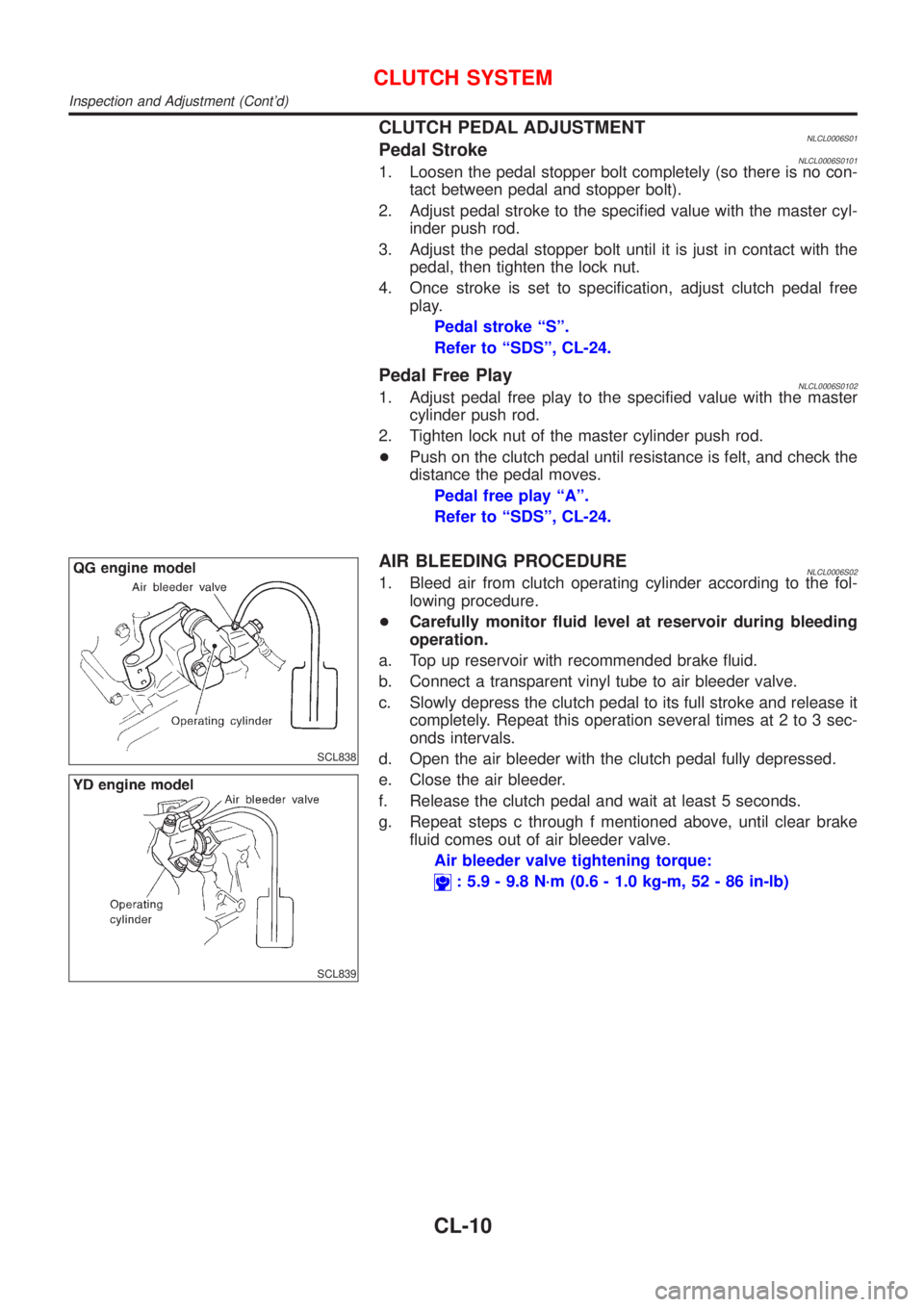
SCL838
SCL839
AIR BLEEDING PROCEDURENLCL0006S021. Bleed air from clutch operating cylinder according to the fol-
lowing procedure.
+Carefully monitor fluid level at reservoir during bleeding
operation.
a. Top up reservoir with recommended brake fluid.
b. Connect a transparent vinyl tube to air bleeder valve.
c. Slowly depress the clutch pedal to its full stroke and release it
completely. Repeat this operation several times at 2 to 3 sec-
onds intervals.
d. Open the air bleeder with the clutch pedal fully depressed.
e. Close the air bleeder.
f. Release the clutch pedal and wait at least 5 seconds.
g. Repeat steps c through f mentioned above, until clear brake
fluid comes out of air bleeder valve.
Air bleeder valve tightening torque:
: 5.9 - 9.8 N´m (0.6 - 1.0 kg-m, 52 - 86 in-lb)
CLUTCH SYSTEM
Inspection and Adjustment (Cont'd)
CL-10
Page 413 of 3051

RemovalNLCL00081. Drain brake fluid.
CAUTION:
Be careful not to splash brake fluid on painted areas; it may
cause paint damage. If brake fluid is splashed on painted
areas, wash it away with water immediately.
2. Remove clutch tube using a flare nut wrench.
3. Remove snap pin between clutch pedal and push rod, and
remove clevis pin.
4. Unscrew master cylinder assembly mounting nuts and remove
master cylinder assembly from vehicle.
InstallationNLCL00091. Connect clutch tube to master cylinder assembly, and hand-
tighten flare nut.
2. Install master cylinder assembly to vehicle, and tighten mount-
ing nuts to the specified torque.
: 13 - 16 N´m (1.3 - 1.6 kg-m, 10 - 12 ft-lb)
3. Tighten clutch tube flare nut using a flare nut torque wrench.
: 15 - 18 N´m (1.5 - 1.8 kg-m, 11 - 13 ft-lb)
4. After installing clevis pin, install snap pin to connect clutch
pedal to push rod.
5. After finishing the operation, bleed air from clutch piping con-
nector and operating cylinder. (Refer to ªAir Bleeding
Procedureº, CL-10.)
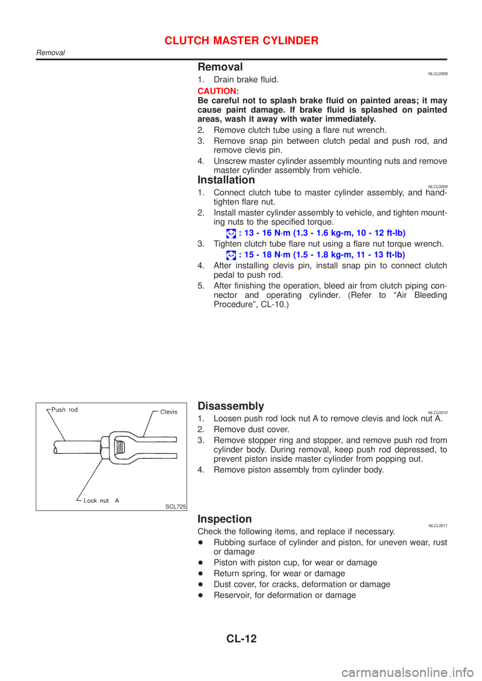
SCL725
DisassemblyNLCL00101. Loosen push rod lock nut A to remove clevis and lock nut A.
2. Remove dust cover.
3. Remove stopper ring and stopper, and remove push rod from
cylinder body. During removal, keep push rod depressed, to
prevent piston inside master cylinder from popping out.
4. Remove piston assembly from cylinder body.
InspectionNLCL0011Check the following items, and replace if necessary.
+Rubbing surface of cylinder and piston, for uneven wear, rust
or damage
+Piston with piston cup, for wear or damage
+Return spring, for wear or damage
+Dust cover, for cracks, deformation or damage
+Reservoir, for deformation or damage
CLUTCH MASTER CYLINDER
Removal
CL-12
Page 415 of 3051
ComponentsNLCL0019
YCL001
RemovalNLCL00201. Drain brake fluid.
CAUTION:
Be careful not to splash brake fluid on painted areas; it may
cause paint damage. If brake fluid is splashed on painted
areas, wash it away with water immediately.
2. Remove union bolt and clutch hose from operating cylinder.
3. Remove operating cylinder mounting bolts, and remove cylin-
der from vehicle.
DisassemblyNLCL0021Remove dust cover, and remove piston assembly from cylinder
body.
InspectionNLCL0022Inspect for following, and replace parts if necessary.
+Damage, foreign material, wear, rust, and pinholes on the cyl-
inder inner surface, piston, and sliding part of piston cup
+Weak spring
+Crack and deformation of dust cover
OPERATING CYLINDER
Components
CL-14
Page 417 of 3051

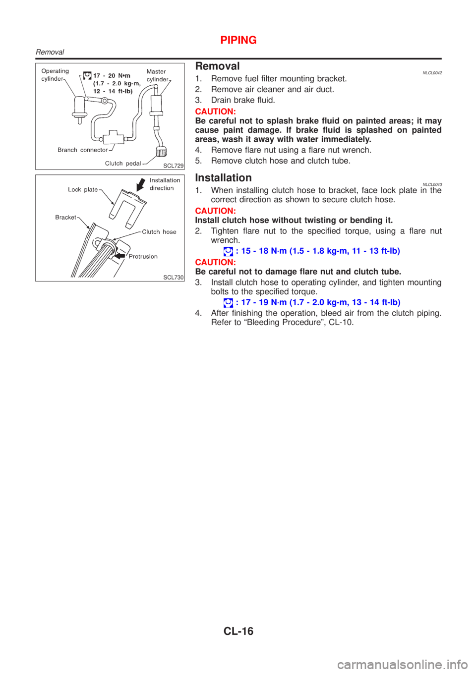
SCL729
RemovalNLCL00421. Remove fuel filter mounting bracket.
2. Remove air cleaner and air duct.
3. Drain brake fluid.
CAUTION:
Be careful not to splash brake fluid on painted areas; it may
cause paint damage. If brake fluid is splashed on painted
areas, wash it away with water immediately.
4. Remove flare nut using a flare nut wrench.
5. Remove clutch hose and clutch tube.
SCL730
InstallationNLCL00431. When installing clutch hose to bracket, face lock plate in the
correct direction as shown to secure clutch hose.
CAUTION:
Install clutch hose without twisting or bending it.
2. Tighten flare nut to the specified torque, using a flare nut
wrench.
: 15 - 18 N´m (1.5 - 1.8 kg-m, 11 - 13 ft-lb)
CAUTION:
Be careful not to damage flare nut and clutch tube.
3. Install clutch hose to operating cylinder, and tighten mounting
bolts to the specified torque.
: 17 - 19 N´m (1.7 - 2.0 kg-m, 13 - 14 ft-lb)
4. After finishing the operation, bleed air from the clutch piping.
Refer to ªBleeding Procedureº, CL-10.
PIPING
Removal
CL-16