2001 NISSAN ALMERA TINO door lock
[x] Cancel search: door lockPage 332 of 3051
BODY & TRIM
SECTION
BT
CONTENTS
PRECAUTIONS...............................................................3
Service Notice..............................................................3
Supplemental Restraint System (SRS)²AIR
BAG²and²SEAT BELT PRE-TENSIONER²...............3
CLIP AND FASTENER....................................................4
Description ...................................................................4
CHASSIS AND BODY MAINTENANCE.........................6
Checking Body Corrosion ............................................6
BODY FRONT END.........................................................7
Removal and Installation .............................................7
FRONT BUMPER ASSEMBLY....................................7
BODY REAR END AND OPENER................................10
Removal and Installation ...........................................10
REAR BUMPER ASSEMBLY....................................10
DOOR.............................................................................13
Adjustment .................................................................13
STRIKER ADJUSTMENT..........................................13
Front Door Glass .......................................................14
FRONT DOOR GLASS AND REGULATOR................14
Front Door Limit Switch Reset (Driver side only)......15
RESET CONDITIONS..............................................15
RESET PROCEDURES............................................15
Rear Door Glass ........................................................16
REAR DOOR GLASS AND REGULATOR..................16
Front Door Lock .........................................................18
OUTSIDE HANDLE ROD ADJUSTMENT...................18
REMOVAL...............................................................18
Rear Door Lock .........................................................20
OUTSIDE HANDLE ROD ADJUSTMENT...................20
REMOVAL...............................................................21
INSTRUMENT PANEL ASSEMBLY.............................22
Removal and Installation ...........................................22
SIDE AND FLOOR TRIM...............................................28
Removal and Installation ...........................................28
LUGGAGE ROOM TRIM...............................................31
Removal and Installation ...........................................31
DOOR TRIM...................................................................32
Removal and Installation ...........................................32ROOF TRIM...................................................................35
Removal and Installation ...........................................35
BACK DOOR TRIM.......................................................37
Removal and Installation ...........................................37
EXTERIOR.....................................................................38
Removal and Installation ...........................................38
FRONT SEAT................................................................46
Removal and Installation ...........................................46
MANUAL SEAT........................................................47
Heated Seat ...............................................................48
Active Head Restraint ................................................48
OPERATION OUTLINE............................................48
REAR SEAT...................................................................49
Removal and Installation ...........................................49
REAR OUTSIDE SEAT.............................................49
REAR CENTER SEAT..............................................50
SUNROOF......................................................................51
Adjustment .................................................................51
Removal .....................................................................51
Trouble Diagnoses.....................................................55
DIAGNOSTIC TABLE................................................55
WIND DEFLECTOR (WHERE FITTED)......................55
ADJUSTMENT.........................................................56
DRAIN HOSES........................................................57
WEATHERSTRIP.....................................................57
LINK AND WIRE ASSEMBLY....................................58
WINDSHIELD AND WINDOWS....................................59
Removal and Installation ...........................................59
REMOVAL...............................................................59
INSTALLATION........................................................59
WINDSHIELD..........................................................60
SIDE WINDOW........................................................61
BACK DOOR WINDOW............................................62
DOOR MIRROR.............................................................63
Removal and Installation ...........................................63
REAR VIEW MIRROR...................................................64
Removal and Installation ...........................................64
REMOVAL...............................................................64
Page 341 of 3051
Removal and InstallationNLBT0034+When removing or installing back door, place a cloth or other padding on back door. This prevents vehicle
body from being scratched.
+Bumper fascia is made of plastic. Do not use excessive force and be sure to keep oil away from it.
+Back door adjustment: Adjust at hinge-back door portion for proper back door fit.
+Back door lock system adjustment: Adjust striker so that it is in the center of the lock. After adjustment,
check back door lock operation.
+After installation, make sure that back door and fuel filler lid open smoothly.
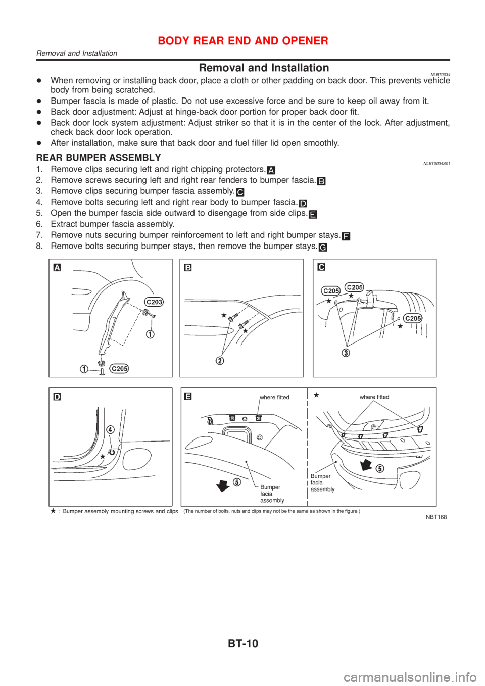
REAR BUMPER ASSEMBLYNLBT0034S011. Remove clips securing left and right chipping protectors.
2. Remove screws securing left and right rear fenders to bumper fascia.
3. Remove clips securing bumper fascia assembly.
4. Remove bolts securing left and right rear body to bumper fascia.
5. Open the bumper fascia side outward to disengage from side clips.
6. Extract bumper fascia assembly.
7. Remove nuts securing bumper reinforcement to left and right bumper stays.
8. Remove bolts securing bumper stays, then remove the bumper stays.
NBT168
BODY REAR END AND OPENER
Removal and Installation
BT-10
Page 344 of 3051
AdjustmentNLBT0006
NBT085
SBT772-B
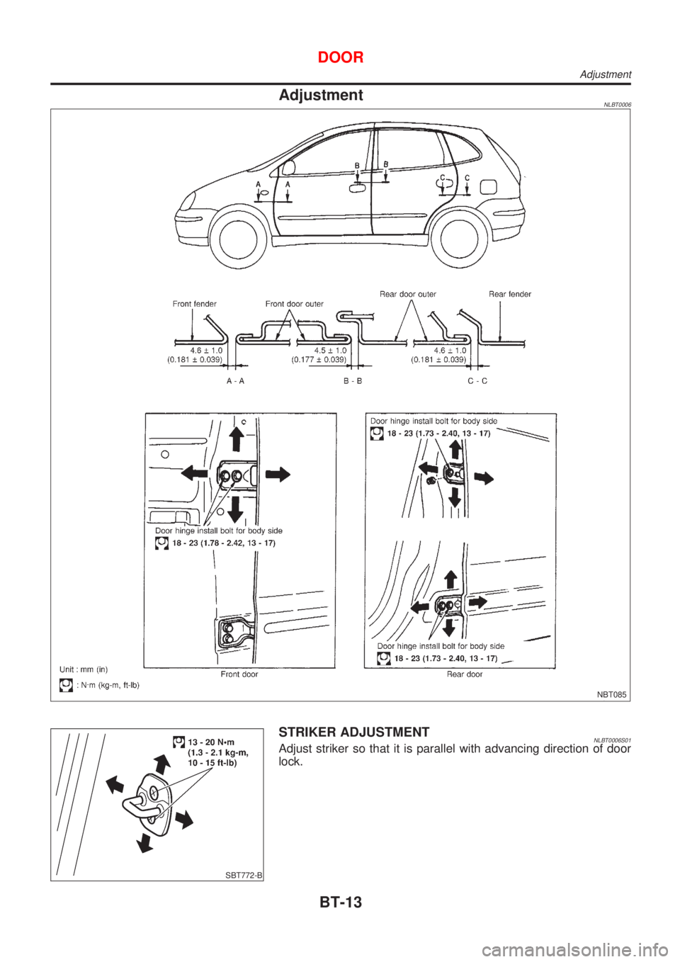
STRIKER ADJUSTMENTNLBT0006S01Adjust striker so that it is parallel with advancing direction of door
lock.
DOOR
Adjustment
BT-13
Page 349 of 3051
Front Door LockNLBT0010
NBT098
+For removal of front door finisher, refer to ªDOOR TRIMº,
BT-32.
+Remove sealing screen.
SBT978
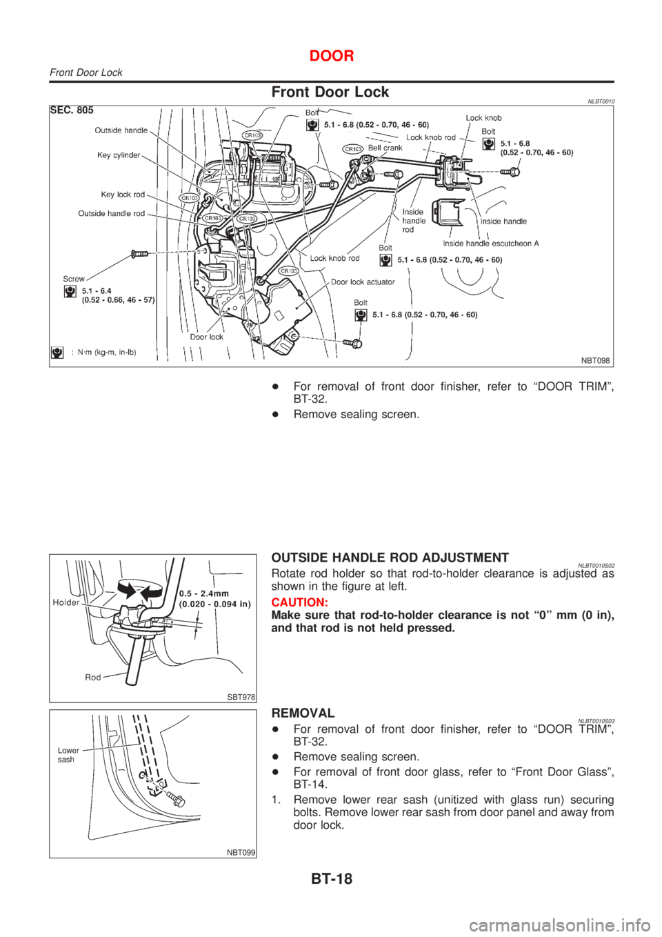
OUTSIDE HANDLE ROD ADJUSTMENTNLBT0010S02Rotate rod holder so that rod-to-holder clearance is adjusted as
shown in the figure at left.
CAUTION:
Make sure that rod-to-holder clearance is not ª0º mm (0 in),
and that rod is not held pressed.
NBT099
REMOVALNLBT0010S03+For removal of front door finisher, refer to ªDOOR TRIMº,
BT-32.
+Remove sealing screen.
+For removal of front door glass, refer to ªFront Door Glassº,
BT-14.
1. Remove lower rear sash (unitized with glass run) securing
bolts. Remove lower rear sash from door panel and away from
door lock.
DOOR
Front Door Lock
BT-18
Page 350 of 3051
NBT100
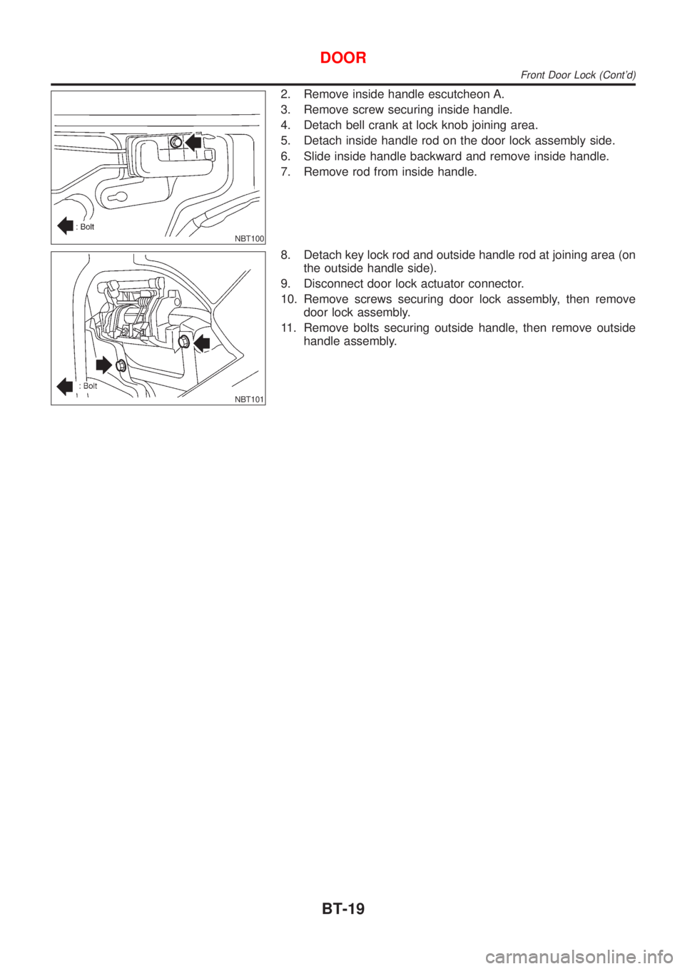
2. Remove inside handle escutcheon A.
3. Remove screw securing inside handle.
4. Detach bell crank at lock knob joining area.
5. Detach inside handle rod on the door lock assembly side.
6. Slide inside handle backward and remove inside handle.
7. Remove rod from inside handle.
NBT101
8. Detach key lock rod and outside handle rod at joining area (on
the outside handle side).
9. Disconnect door lock actuator connector.
10. Remove screws securing door lock assembly, then remove
door lock assembly.
11. Remove bolts securing outside handle, then remove outside
handle assembly.
DOOR
Front Door Lock (Cont'd)
BT-19
Page 351 of 3051
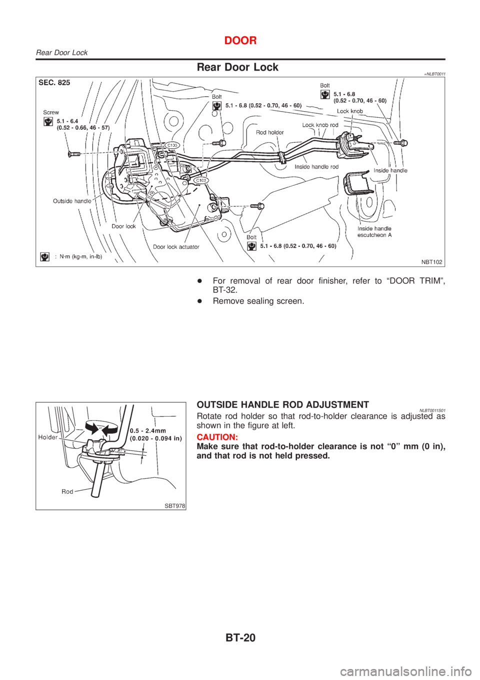
Rear Door Lock=NLBT0011
NBT102
+For removal of rear door finisher, refer to ªDOOR TRIMº,
BT-32.
+Remove sealing screen.
SBT978
OUTSIDE HANDLE ROD ADJUSTMENTNLBT0011S01Rotate rod holder so that rod-to-holder clearance is adjusted as
shown in the figure at left.
CAUTION:
Make sure that rod-to-holder clearance is not ª0º mm (0 in),
and that rod is not held pressed.
DOOR
Rear Door Lock
BT-20
Page 352 of 3051
SBT983
REMOVAL=NLBT0011S02+For removal of rear door finisher, refer to ªDOOR TRIMº,
BT-32.
+Remove sealing screen.
+Set the door glass in the full-close position.
1. Remove inside handle escutcheon A.
2. Remove screw securing inside handle.
3. Detach inside handle rod on the door lock assembly side.
NBT103
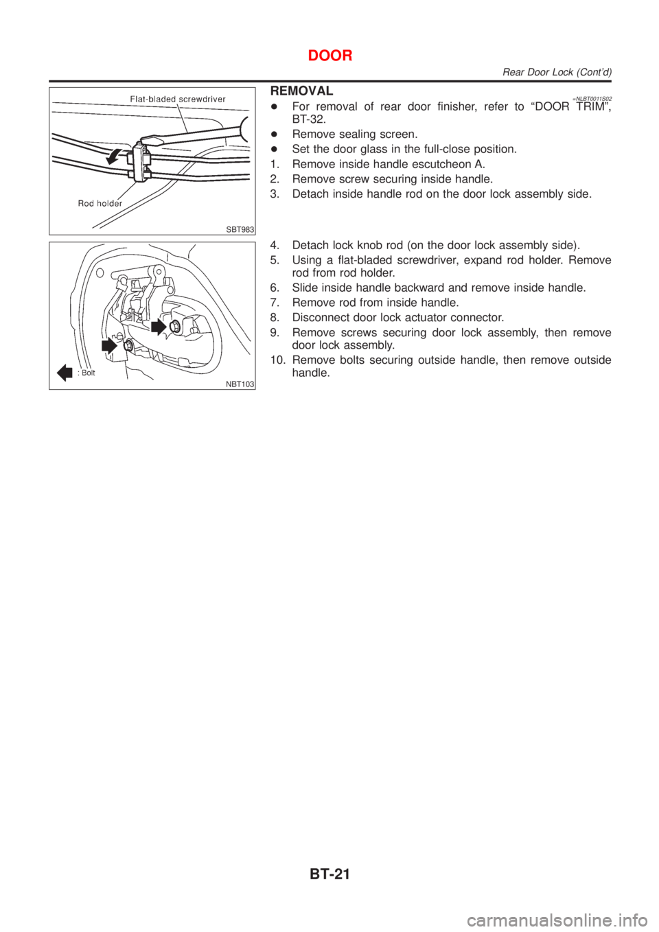
4. Detach lock knob rod (on the door lock assembly side).
5. Using a flat-bladed screwdriver, expand rod holder. Remove
rod from rod holder.
6. Slide inside handle backward and remove inside handle.
7. Remove rod from inside handle.
8. Disconnect door lock actuator connector.
9. Remove screws securing door lock assembly, then remove
door lock assembly.
10. Remove bolts securing outside handle, then remove outside
handle.
DOOR
Rear Door Lock (Cont'd)
BT-21
Page 1733 of 3051
Electrical Components Inspection ...........................164
WARNING CHIME.......................................................165
Component Parts and Harness Connector
Location ...................................................................165
System Description ..................................................165
Wiring Diagram - CHIME - ......................................166
Trouble Diagnoses...................................................170
FRONT WIPER AND WASHER..................................176
System Description ..................................................176
Wiring Diagram - WIPER - ......................................178
Removal and Installation .........................................182
Washer Nozzle Adjustment .....................................183
Washer Tube Layout ...............................................183
REAR WIPER AND WASHER....................................184
Wiring Diagram - WIP/R -........................................184
Removal and Installation .........................................188
Washer Nozzle Adjustment .....................................188
Washer Tube Layout ...............................................189
HEADLAMP WASHER................................................190
Wiring Diagram - HLC - ...........................................190
Washer Tube Layout ...............................................192
HORN...........................................................................193
Wiring Diagram - HORN - .......................................193
CIGARETTE LIGHTER................................................195
Wiring Diagram - CIGAR -.......................................195
CLOCK.........................................................................196
Wiring Diagram - CLOCK -......................................196
REAR WINDOW DEFOGGER.....................................198
System Description ..................................................198
Wiring Diagram - DEF - ...........................................199
Trouble Diagnoses...................................................203
Electrical Components Inspection ...........................205
Filament Check ........................................................206
Filament Repair .......................................................207
AUDIO..........................................................................208
System Description ..................................................208
Schematic ................................................................210
Wiring Diagram - AUDIO - .......................................212
Trouble Diagnoses...................................................230
Inspection.................................................................232
AUDIO ANTENNA.......................................................233
Location of Antenna .................................................233
Antenna Rod Replacement .....................................233
HEATED SEAT............................................................234
Wiring Diagram - H/SEAT - .....................................234
POWER SUNROOF.....................................................238
Wiring Diagram - SROOF - .....................................238
Trouble Diagnoses...................................................240
DOOR MIRROR...........................................................241
Wiring Diagram - MIRROR - ...................................241
POWER WINDOW.......................................................245
System Description ..................................................245Schematic ................................................................247
Wiring Diagram - WINDOW - ..................................248
Trouble Diagnoses...................................................256
POWER DOOR LOCK.................................................257
Component Parts and Harness Connector
Location/LHD Models ..............................................257
System Description/LHD Models .............................257
Schematic/LHD Models ...........................................258
Wiring Diagram - D/LOCK -/LHD Models................260
Trouble Diagnoses/LHD Models..............................272
POWER DOOR LOCK - SUPER LOCK -...................281
System Description/RHD Models ............................281
Schematic/RHD Models...........................................284
Wiring Diagram - S/LOCK -/RHD Models ...............286
Trouble Diagnoses/RHD Models .............................300
MULTI-REMOTE CONTROL SYSTEM.......................314
System Description ..................................................314
Wiring Diagram - MULTI - .......................................315
Trouble Diagnoses...................................................319
ID Code Entry Procedure ........................................324
Remote Controller Battery Replacement.................325
TIME CONTROL UNIT................................................326
Description ...............................................................326
Trouble Diagnoses...................................................327
Schematic ................................................................330
NATS (NISSAN ANTI-THEFT SYSTEM).....................334
Component Parts and Harness Connector
Location ...................................................................334
System Description ..................................................334
System Composition ................................................335
Schematic ................................................................336
Wiring Diagram - NATS -.........................................338
CONSULT-II .............................................................346
Trouble Diagnoses...................................................349
How to Replace NATS IMMU ..................................369
NAVIGATION SYSTEM...............................................370
Precautions ..............................................................370
Component Parts Location ......................................370
System Description ..................................................370
Schematic ................................................................379
Wiring Diagram - NAVI - ..........................................381
Self-diagnosis Mode ................................................401
Confirmation/Adjustment Mode ...............................404
Control Panel Mode .................................................416
Guide Volume Setting ..............................................423
Anti-theft System .....................................................424
CONSULT-II .............................................................425
Trouble Diagnoses...................................................426
This Condition Is Not Abnormal...............................432
Program Loading .....................................................441
ELECTRICAL UNITS LOCATION...............................442
Engine Compartment ...............................................442
CONTENTS(Cont'd)
EL-2