2001 NISSAN ALMERA TINO clutch
[x] Cancel search: clutchPage 1 of 3051

Release:April 2001 01)GENERALINFORMATIONGIMAINTENANCEMAENGINEMECHANICALEMENGINELUBRICATION&
COOLINGSYSTEMSLCENGINECONTROLSYSTEMECACCELERATORCONTROL,
FUEL&EXHAUSTSYSTEMSFECLUTCHCLMANUALTRANSAXLEMTAUTOMATICTRANSAXLEATFRONT&REARAXLEAXFRONT&REARSUSPENSIONSUBRAKESYSTEMBRSTEERINGSYSTEMSTRESTRAINTSYSTEMRSBODY&TRIMBTHEATER&AIRCONDITIONERHASTARTING&CHARGINGSYSTEMSSCELECTRICALSYSTEMELALPHABETICALINDEXIDXALMERATINOMODELV10SERIESQUICKREFERENCEINDEX
Page 3 of 3051

Wiring Diagram - AT - FTS ........................................75
Diagnostic Procedure ................................................77
DTC P0715 PRIMARY SPEED SENSOR.....................79
Description .................................................................79
Wiring Diagram - AT - PSSA/T ..................................80
Diagnostic Procedure ................................................82
Component Inspection ...............................................83
DTC P0720 VEHICLE SPEED SENSOR
(SECONDARY SPEED SENSOR)................................84
Description .................................................................84
Wiring Diagram - AT - VSSA/T ..................................86
Diagnostic Procedure ................................................88
Component Inspection ...............................................89
DTC P0725 ENGINE SPEED SIGNAL.........................90
Description .................................................................90
Wiring Diagram - AT - ENGSS ..................................91
Diagnostic Procedure ................................................92
DTC P0740 TORQUE CONVERTER CLUTCH
SOLENOID VALVE........................................................94
Description .................................................................94
Wiring Diagram - AT - TCV........................................96
Diagnostic Procedure ................................................97
Component Inspection ...............................................98
DTC P0745 LINE PRESSURE SOLENOID VALVE.....99
Description .................................................................99
Wiring Diagram - AT - LPSV....................................101
Diagnostic Procedure ..............................................102
Component Inspection .............................................103
DTC P1705 THROTTLE POSITION SENSOR...........104
Description ...............................................................104
Wiring Diagram - AT - TPS ......................................106
Diagnostic Procedure ..............................................108
Component Inspection ............................................. 111
DTC P1777 STEP MOTOR - CIRCUIT....................... 112
Description ............................................................... 112
Wiring Diagram - AT - STM ..................................... 114
Diagnostic Procedure .............................................. 115
Component Inspection ............................................. 116
DTC P1778 STEP MOTOR - FUNCTION................... 117
Description ............................................................... 117
Diagnostic Procedure .............................................. 118
DTC P1791 LINE PRESSURE SENSOR.................... 119
Description ............................................................... 119
Wiring Diagram - AT - LPS ......................................121
Diagnostic Procedure ..............................................123
Component Inspection .............................................124
CVT SAFE FUNCTION................................................125
Description ...............................................................125
Diagnostic Procedure ..............................................125EXCEPT FOR EURO-OBD
VEHICLE SPEED SENSOR CVT (SECONDARY
SPEED SENSOR)........................................................126
Description ...............................................................126
Wiring Diagram - AT - VSSA/T ................................128
Diagnostic Procedure ..............................................130
PRIMARY SPEED SENSOR.......................................132
Description ...............................................................132
Wiring Diagram - AT - VSSMTR ..............................134
Diagnostic Procedure ..............................................136
THROTTLE POSITION SENSOR................................137
Description ...............................................................137
Wiring Diagram - AT - TPS ......................................139
Diagnostic Procedure ..............................................141
Component Inspection .............................................145
STEPPING MOTOR - CIRCUIT...................................146
Description ...............................................................146
Wiring Diagram - AT - STM .....................................147
Diagnostic Procedure ..............................................148
Component Inspection .............................................149
STEP MOTOR - FUNCTION.......................................150
Description ...............................................................150
Diagnostic Procedure ..............................................150
LINE PRESSURE SENSOR........................................151
Description ...............................................................151
Wiring Diagram - AT - LPS ......................................153
Diagnostic Procedure ..............................................155
Component Inspection .............................................156
LINE PRESSURE SOLENOID VALVE.......................157
Description ...............................................................157
Wiring Diagram - AT - LPSV....................................159
Diagnostic Procedure ..............................................160
Component Inspection .............................................163
TORQUE CONVERTER CLUTCH SOLENOID
VALVE..........................................................................164
Description ...............................................................164
Wiring Diagram - AT - TCV......................................166
Diagnostic Procedure ..............................................167
Component Inspection .............................................169
CVT FLUID TEMPERATURE SENSOR CIRCUIT......170
Description ...............................................................170
Wiring Diagram - AT - FTS ......................................172
Diagnostic Procedure ..............................................174
ENGINE SPEED SIGNAL............................................176
Description ...............................................................176
Wiring Diagram - AT - ENGSS ................................177
Diagnostic Procedure ..............................................178
CONTROL UNIT (RAM), CONTROL UNIT (ROM).....180
Description ...............................................................180
Diagnostic Procedure ..............................................181
CONTENTS(Cont'd)
AT-2
Page 16 of 3051
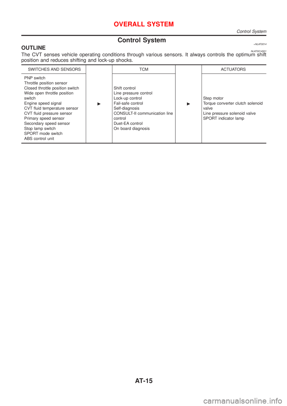
Control System=NLAT0014OUTLINENLAT0014S01The CVT senses vehicle operating conditions through various sensors. It always controls the optimum shift
position and reduces shifting and lock-up shocks.
SWITCHES AND SENSORS
cTCM
cACTUATORS
PNP switch
Throttle position sensor
Closed throttle position switch
Wide open throttle position
switch
Engine speed signal
CVT fluid temperature sensor
CVT fluid pressure sensor
Primary speed sensor
Secondary speed sensor
Stop lamp switch
SPORT mode switch
ABS control unitShift control
Line pressure control
Lock-up control
Fail-safe control
Self-diagnosis
CONSULT-II communication line
control
Duet-EA control
On board diagnosisStep motor
Torque converter clutch solenoid
valve
Line pressure solenoid valve
SPORT indicator lamp
OVERALL SYSTEM
Control System
AT-15
Page 18 of 3051
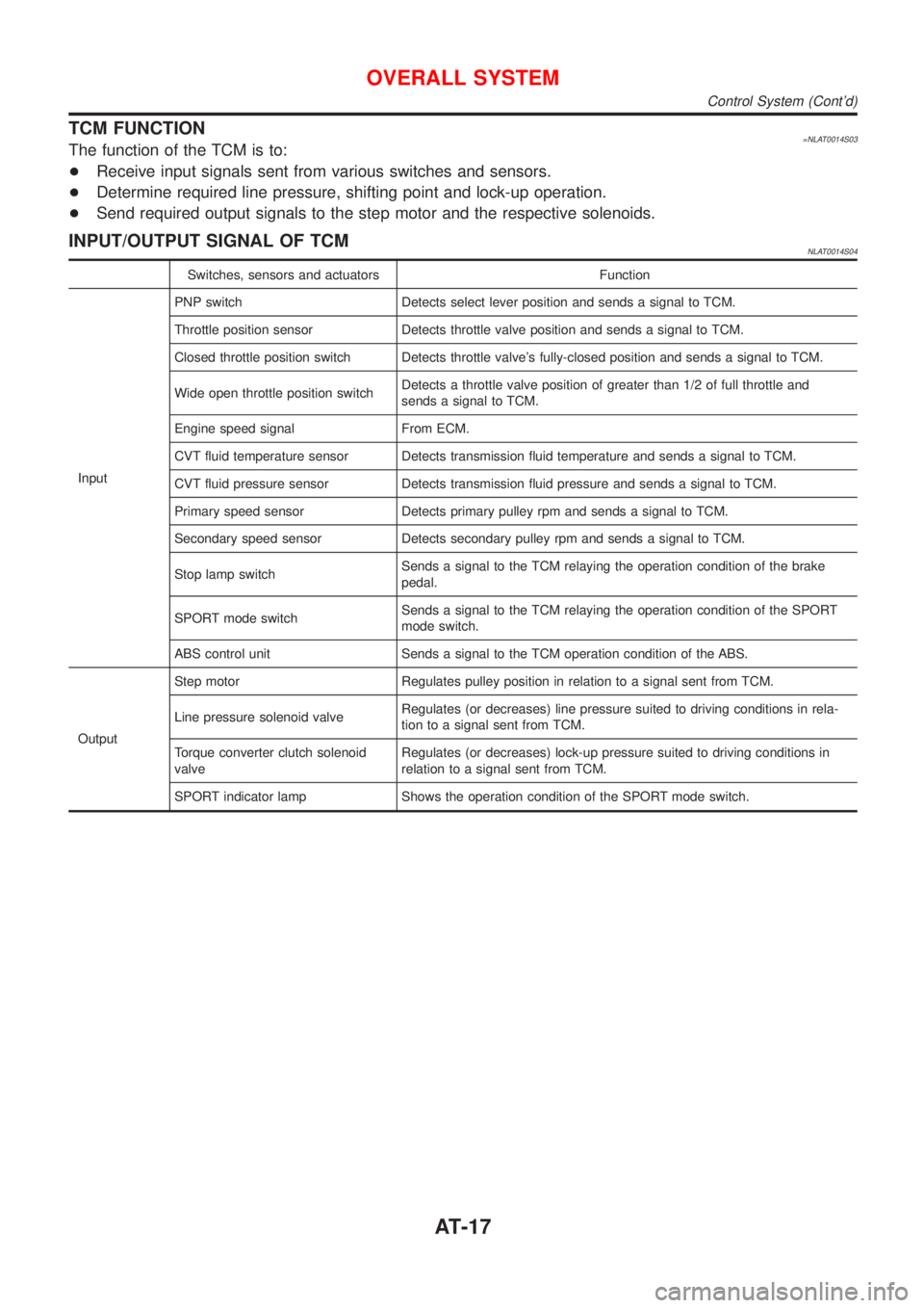
TCM FUNCTION=NLAT0014S03The function of the TCM is to:
+Receive input signals sent from various switches and sensors.
+Determine required line pressure, shifting point and lock-up operation.
+Send required output signals to the step motor and the respective solenoids.
INPUT/OUTPUT SIGNAL OF TCMNLAT0014S04
Switches, sensors and actuators Function
InputPNP switch Detects select lever position and sends a signal to TCM.
Throttle position sensor Detects throttle valve position and sends a signal to TCM.
Closed throttle position switch Detects throttle valve's fully-closed position and sends a signal to TCM.
Wide open throttle position switchDetects a throttle valve position of greater than 1/2 of full throttle and
sends a signal to TCM.
Engine speed signal From ECM.
CVT fluid temperature sensor Detects transmission fluid temperature and sends a signal to TCM.
CVT fluid pressure sensor Detects transmission fluid pressure and sends a signal to TCM.
Primary speed sensor Detects primary pulley rpm and sends a signal to TCM.
Secondary speed sensor Detects secondary pulley rpm and sends a signal to TCM.
Stop lamp switchSends a signal to the TCM relaying the operation condition of the brake
pedal.
SPORT mode switchSends a signal to the TCM relaying the operation condition of the SPORT
mode switch.
ABS control unit Sends a signal to the TCM operation condition of the ABS.
OutputStep motor Regulates pulley position in relation to a signal sent from TCM.
Line pressure solenoid valveRegulates (or decreases) line pressure suited to driving conditions in rela-
tion to a signal sent from TCM.
Torque converter clutch solenoid
valveRegulates (or decreases) lock-up pressure suited to driving conditions in
relation to a signal sent from TCM.
SPORT indicator lamp Shows the operation condition of the SPORT mode switch.
OVERALL SYSTEM
Control System (Cont'd)
AT-17
Page 23 of 3051
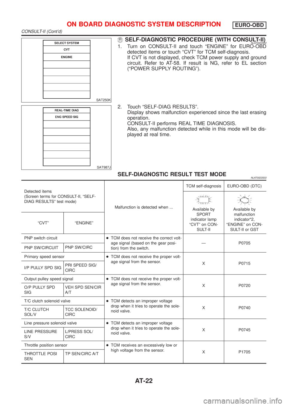
SAT250K
SELF-DIAGNOSTIC PROCEDURE (WITH CONSULT-II)NLAT0022S021. Turn on CONSULT-II and touch ªENGINEº for EURO-OBD
detected items or touch ªCVTº for TCM self-diagnosis.
If CVT is not displayed, check TCM power supply and ground
circuit. Refer to AT-58. If result is NG, refer to EL section
(ªPOWER SUPPLY ROUTINGº).
SAT987J
2. Touch ªSELF-DIAG RESULTSº.
Display shows malfunction experienced since the last erasing
operation.
CONSULT-II performs REAL TIME DIAGNOSIS.
Also, any malfunction detected while in this mode will be dis-
played at real time.
SELF-DIAGNOSTIC RESULT TEST MODENLAT0022S03
Detected items
(Screen terms for CONSULT-II, ªSELF-
DIAG RESULTSº test mode)
Malfunction is detected when ...TCM self-diagnosis EURO-OBD (DTC)
Available by
SPORT
indicator lamp
ªCVTº on CON-
SULT-IIAvailable by
malfunction
indicator*2,
ªENGINEº on CON-
SULT-II or GST ªCVTº ªENGINEº
PNP switch circuit+TCM does not receive the correct volt-
age signal (based on the gear posi-
tion) from the switch.Ð P0705
PNP SW/CIRCUITPNP SW/CIRC
Primary speed sensor+TCM does not receive the proper volt-
age signal from the sensor.
X P0715
I/P PULLY SPD SIGPRI SPEED SIG/
CIRC
Output pulley speed signal+TCM does not receive the proper volt-
age signal from the sensor.
X P0720
O/P PULLY SPD
SIGVEH SPD SEN/CIR
A/T
T/C clutch solenoid valve+TCM detects an improper voltage
drop when it tries to operate the sole-
noid valve.X P0740
T/C CLUTCH
SOL/VTCC SOLENOID/
CIRC
Line pressure solenoid valve+TCM detects an improper voltage
drop when it tries to operate the sole-
noid valve.X P0745
LINE PRESSURE
S/VL/PRESS SOL/
CIRC
Throttle position sensor+TCM receives an excessively low or
high voltage from the sensor.
X P1705
THROTTLE POSI
SENTP SEN/CIRC A/T
ON BOARD DIAGNOSTIC SYSTEM DESCRIPTIONEURO-OBD
CONSULT-II (Cont'd)
AT-22
Page 26 of 3051
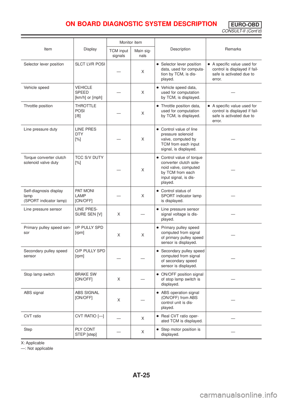
Item DisplayMonitor item
Description Remarks
TCM input
signalsMain sig-
nals
Selector lever position SLCT LVR POSI
ÐX+Selector lever position
data, used for computa-
tion by TCM, is dis-
played.+A specific value used for
control is displayed if fail-
safe is activated due to
error.
Vehicle speed VEHICLE
SPEED
[km/h] or [mph]ÐX+Vehicle speed data,
used for computation
by TCM, is displayed.Ð
Throttle position THROTTLE
POSI
[/8]ÐX+Throttle position data,
used for computation
by TCM, is displayed.+A specific value used for
control is displayed if fail-
safe is activated due to
error.
Line pressure duty LINE PRES
DTY
[%] Ð X+Control value of line
pressure solenoid
valve, computed by
TCM from each input
signal, is displayed.Ð
Torque converter clutch
solenoid valve dutyTCC S/V DUTY
[%]
ÐX+Control value of torque
converter clutch sole-
noid valve, computed
by TCM from each
input signal, is dis-
played.Ð
Self-diagnosis display
lamp
(SPORT indicator lamp)PAT MONI
LAMP
[ON/OFF]ÐX+Control status of
SPORT indicator lamp
is displayed.Ð
Line pressure sensor LINE PRES-
SURE SEN [V] X Ð+Line pressure sensor
signal voltage is dis-
played.Ð
Primary pulley speed sen-
sorI/P PULLY SPD
[rpm]
XX+Primary pulley speed
computed from signal
of primary pulley speed
sensor is displayed.Ð
Secondary pulley speed
sensorO/P PULLY SPD
[rpm]
ÐÐ+Secondary pulley speed
computed from signal
of secondary speed
sensor is displayed.Ð
Stop lamp switch BRAKE SW
[ON/OFF] X Ð+ON/OFF position signal
of stop lamp switch is
displayed.Ð
ABS signal ABS SIGNAL
[ON/OFF]
XÐ+ABS operation signal
(ON/OFF) from ABS
control unit is dis-
played.Ð
CVT ratio CVT RATIO [Ð]
ÐX+Real CVT ratio oper-
ated TCM is displayed.Ð
Step PLY CONT
STEP [step]ÐX+Step motor position is
displayed.Ð
X: Applicable
Ð: Not applicable
ON BOARD DIAGNOSTIC SYSTEM DESCRIPTIONEURO-OBD
CONSULT-II (Cont'd)
AT-25
Page 30 of 3051
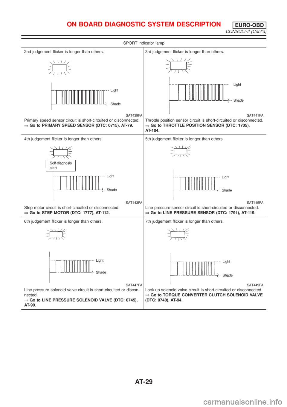
SPORT indicator lamp
2nd judgement flicker is longer than others.
SAT439FA
Primary speed sensor circuit is short-circuited or disconnected.
ÞGo to PRIMARY SPEED SENSOR (DTC: 0715), AT-79.3rd judgement flicker is longer than others.
SAT441FA
Throttle position sensor circuit is short-circuited or disconnected.
ÞGo to THROTTLE POSITION SENSOR (DTC: 1705),
AT-104.
4th judgement flicker is longer than others.
SAT443FA
Step motor circuit is short-circuited or disconnected.
ÞGo to STEP MOTOR (DTC: 1777), AT-112.5th judgement flicker is longer than others.
SAT445FA
Line pressure sensor circuit is short-circuited or disconnected.
ÞGo to LINE PRESSURE SENSOR (DTC: 1791), AT-119.
6th judgement flicker is longer than others.
SAT447FA
Line pressure solenoid valve circuit is short-circuited or discon-
nected.
ÞGo to LINE PRESSURE SOLENOID VALVE (DTC: 0745),
AT-99.7th judgement flicker is longer than others.
SAT449FA
Lock up solenoid valve circuit is short-circuited or disconnected.
ÞGo to TORQUE CONVERTER CLUTCH SOLENOID VALVE
(DTC: 0740), AT-94.
ON BOARD DIAGNOSTIC SYSTEM DESCRIPTIONEURO-OBD
CONSULT-II (Cont'd)
AT-29
Page 33 of 3051
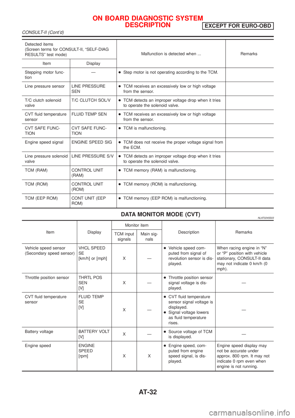
Detected items
(Screen terms for CONSULT-II, ªSELF-DIAG
RESULTSº test mode)Malfunction is detected when ... Remarks
Item Display
Stepping motor func-
tionÐ+Step motor is not operating according to the TCM.
Line pressure sensor LINE PRESSURE
SEN+TCM receives an excessively low or high voltage
from the sensor.
T/C clutch solenoid
valveT/C CLUTCH SOL/V+TCM detects an improper voltage drop when it tries
to operate the solenoid valve.
CVT fluid temperature
sensorFLUID TEMP SEN+TCM receives an excessively low or high voltage
from the sensor.
CVT SAFE FUNC-
TIONCVT SAFE FUNC-
TION+TCM is malfunctioning.
Engine speed signal ENGINE SPEED SIG+TCM does not receive the proper voltage signal from
the ECM.
Line pressure solenoid
valveLINE PRESSURE S/V+TCM detects an improper voltage drop when it tries
to operate the solenoid valve.
TCM (RAM) CONTROL UNIT
(RAM)+TCM memory (RAM) is malfunctioning.
TCM (ROM) CONTROL UNIT
(ROM)+TCM memory (ROM) is malfunctioning.
TCM (EEP ROM) CONT UNIT (EEP
ROM)+TCM memory (EEP ROM) is malfunctioning.
DATA MONITOR MODE (CVT)NLAT0245S03
Item DisplayMonitor item
Description Remarks
TCM input
signalsMain sig-
nals
Vehicle speed sensor
(Secondary speed sensor)VHCL SPEED
SE
[km/h] or [mph] X Ð+Vehicle speed com-
puted from signal of
revolution sensor is dis-
played.When racing engine in ªNº
or ªPº position with vehicle
stationary, CONSULT-II data
may not indicate 0 km/h (0
mph).
Throttle position sensor THRTL POS
SEN
[V]XÐ+Throttle position sensor
signal voltage is dis-
played.Ð
CVT fluid temperature
sensorFLUID TEMP
SE
[V]
XÐ+CVT fluid temperature
sensor signal voltage is
displayed.
+Signal voltage lowers
as fluid temperature
rises.Ð
Battery voltage BATTERY VOLT
[V]XÐ+Source voltage of TCM
is displayed.Ð
Engine speed ENGINE
SPEED
[rpm] X X+Engine speed, com-
puted from engine
speed signal, is dis-
played.Engine speed display may
not be accurate under
approx. 800 rpm. It may not
indicate 0 rpm even when
engine is not running.
ON BOARD DIAGNOSTIC SYSTEM
DESCRIPTION
EXCEPT FOR EURO-OBD
CONSULT-II (Cont'd)
AT-32