2001 NISSAN ALMERA TINO check engine light
[x] Cancel search: check engine lightPage 22 of 3051
HOW TO ERASE DTC (WITH GST)=NLAT0020S041. If the ignition switch stays ªONº after repair work, be sure to turn ignition switch ªOFFº once. Wait at least
5 seconds and then turn it ªONº (engine stopped) again.
2. Perform ªEURO-OBD SELF-DIAGNOSTIC PROCEDURE (No Tools)º. Refer to AT-28. (The engine
warm-up step can be skipped when performing the diagnosis only to erase the DTC.)
3. Select Mode 4 with Generic Scan Tool (GST). For details, refer to EC section ªGeneric Scan Tool (GST)º.
HOW TO ERASE DTC (NO TOOLS)NLAT0020S051. If the ignition switch stays ªONº after repair work, be sure to turn ignition switch ªOFFº once. Wait at least
5 seconds and then turn it ªONº (engine stopped) again.
2. Perform ªTCM SELF-DIAGNOSTIC PROCEDURE (No Tools)º. Refer to AT-28. (The engine warm-up step
can be skipped when performing the diagnosis only to erase the DTC.)
3. Change the diagnostic test mode from Mode II to Mode I by turning the mode selector on the ECM.
Refer to EC section ªHOW TO SWITCH DIAGNOSTIC TEST MODESº.
SAT652J
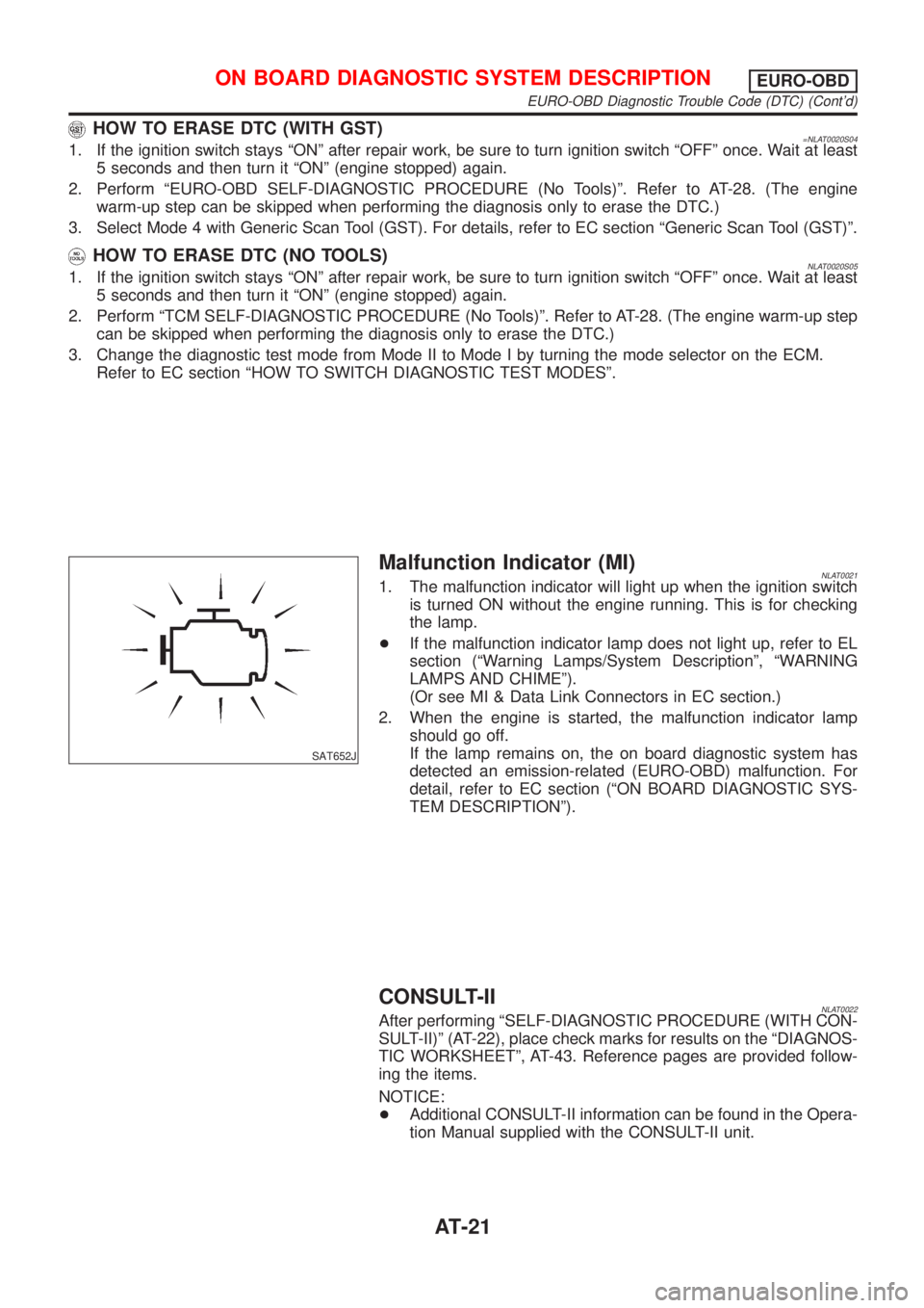
Malfunction Indicator (MI)NLAT00211. The malfunction indicator will light up when the ignition switch
is turned ON without the engine running. This is for checking
the lamp.
+If the malfunction indicator lamp does not light up, refer to EL
section (ªWarning Lamps/System Descriptionº, ªWARNING
LAMPS AND CHIMEº).
(Or see MI & Data Link Connectors in EC section.)
2. When the engine is started, the malfunction indicator lamp
should go off.
If the lamp remains on, the on board diagnostic system has
detected an emission-related (EURO-OBD) malfunction. For
detail, refer to EC section (ªON BOARD DIAGNOSTIC SYS-
TEM DESCRIPTIONº).
CONSULT-IINLAT0022After performing ªSELF-DIAGNOSTIC PROCEDURE (WITH CON-
SULT-II)º (AT-22), place check marks for results on the ªDIAGNOS-
TIC WORKSHEETº, AT-43. Reference pages are provided follow-
ing the items.
NOTICE:
+Additional CONSULT-II information can be found in the Opera-
tion Manual supplied with the CONSULT-II unit.
ON BOARD DIAGNOSTIC SYSTEM DESCRIPTIONEURO-OBD
EURO-OBD Diagnostic Trouble Code (DTC) (Cont'd)
AT-21
Page 52 of 3051
SAT767B
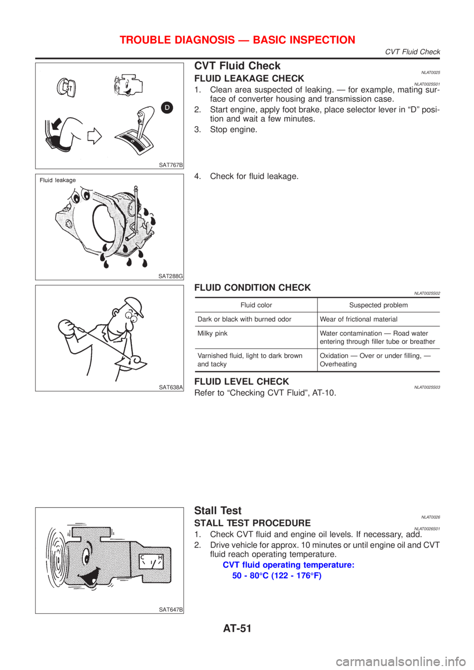
CVT Fluid CheckNLAT0025FLUID LEAKAGE CHECKNLAT0025S011. Clean area suspected of leaking. Ð for example, mating sur-
face of converter housing and transmission case.
2. Start engine, apply foot brake, place selector lever in ªDº posi-
tion and wait a few minutes.
3. Stop engine.
SAT288G
4. Check for fluid leakage.
SAT638A
FLUID CONDITION CHECKNLAT0025S02
Fluid color Suspected problem
Dark or black with burned odor Wear of frictional material
Milky pink Water contamination Ð Road water
entering through filler tube or breather
Varnished fluid, light to dark brown
and tackyOxidation Ð Over or under filling, Ð
Overheating
FLUID LEVEL CHECKNLAT0025S03Refer to ªChecking CVT Fluidº, AT-10.
SAT647B
Stall TestNLAT0026STALL TEST PROCEDURENLAT0026S011. Check CVT fluid and engine oil levels. If necessary, add.
2. Drive vehicle for approx. 10 minutes or until engine oil and CVT
fluid reach operating temperature.
CVT fluid operating temperature:
50 - 80ÉC (122 - 176ÉF)
TROUBLE DIAGNOSIS Ð BASIC INSPECTION
CVT Fluid Check
AT-51
Page 208 of 3051
SAT266K
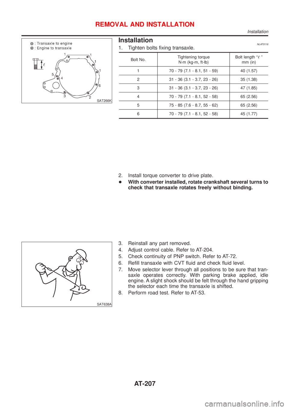
InstallationNLAT01161. Tighten bolts fixing transaxle.
Bolt No.Tightening torque
N´m (kg-m, ft-lb)Bolt length ª!º
mm (in)
1 70 - 79 (7.1 - 8.1, 51 - 59) 40 (1.57)
2 31 - 36 (3.1 - 3.7, 23 - 26) 35 (1.38)
3 31 - 36 (3.1 - 3.7, 23 - 26) 47 (1.85)
4 70 - 79 (7.1 - 8.1, 52 - 58) 65 (2.56)
5 75 - 85 (7.6 - 8.7, 55 - 62) 65 (2.56)
6 70 - 79 (7.1 - 8.1, 52 - 58) 45 (1.77)
2. Install torque converter to drive plate.
+With converter installed, rotate crankshaft several turns to
check that transaxle rotates freely without binding.
SAT638A
3. Reinstall any part removed.
4. Adjust control cable. Refer to AT-204.
5. Check continuity of PNP switch. Refer to AT-72.
6. Refill transaxle with CVT fluid and check fluid level.
7. Move selector lever through all positions to be sure that tran-
saxle operates correctly. With parking brake applied, idle
engine. A slight shock should be felt through the hand gripping
the selector each time the transaxle is shifted.
8. Perform road test. Refer to AT-53.
REMOVAL AND INSTALLATION
Installation
AT-207
Page 253 of 3051
SBR002A
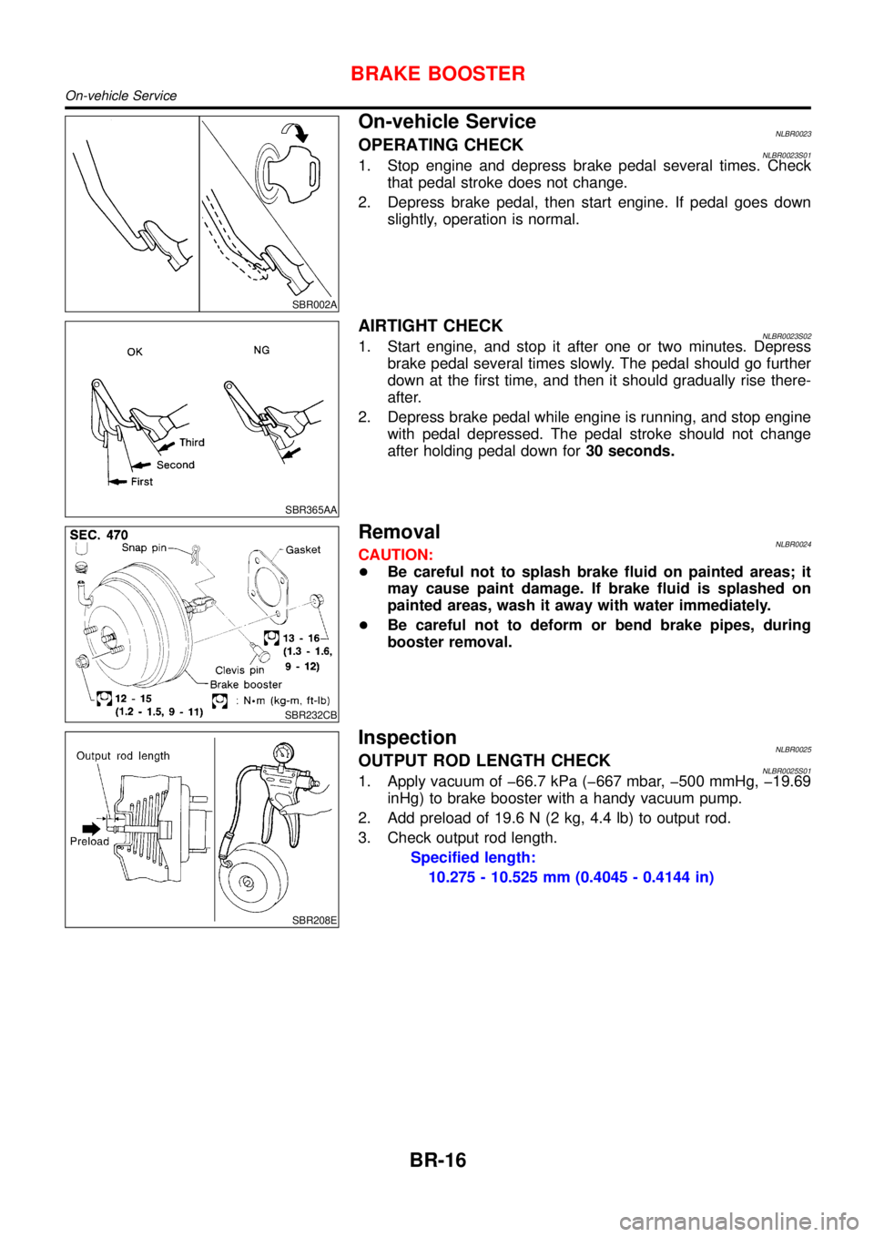
On-vehicle ServiceNLBR0023OPERATING CHECKNLBR0023S011. Stop engine and depress brake pedal several times. Check
that pedal stroke does not change.
2. Depress brake pedal, then start engine. If pedal goes down
slightly, operation is normal.
SBR365AA
AIRTIGHT CHECKNLBR0023S021. Start engine, and stop it after one or two minutes. Depress
brake pedal several times slowly. The pedal should go further
down at the first time, and then it should gradually rise there-
after.
2. Depress brake pedal while engine is running, and stop engine
with pedal depressed. The pedal stroke should not change
after holding pedal down for30 seconds.
SBR232CB
RemovalNLBR0024CAUTION:
+Be careful not to splash brake fluid on painted areas; it
may cause paint damage. If brake fluid is splashed on
painted areas, wash it away with water immediately.
+Be careful not to deform or bend brake pipes, during
booster removal.
SBR208E
InspectionNLBR0025OUTPUT ROD LENGTH CHECKNLBR0025S011. Apply vacuum of �66.7 kPa (�667 mbar, �500 mmHg, �19.69
inHg) to brake booster with a handy vacuum pump.
2. Add preload of 19.6 N (2 kg, 4.4 lb) to output rod.
3. Check output rod length.
Specified length:
10.275 - 10.525 mm (0.4045 - 0.4144 in)
BRAKE BOOSTER
On-vehicle Service
BR-16
Page 448 of 3051
MEF040D
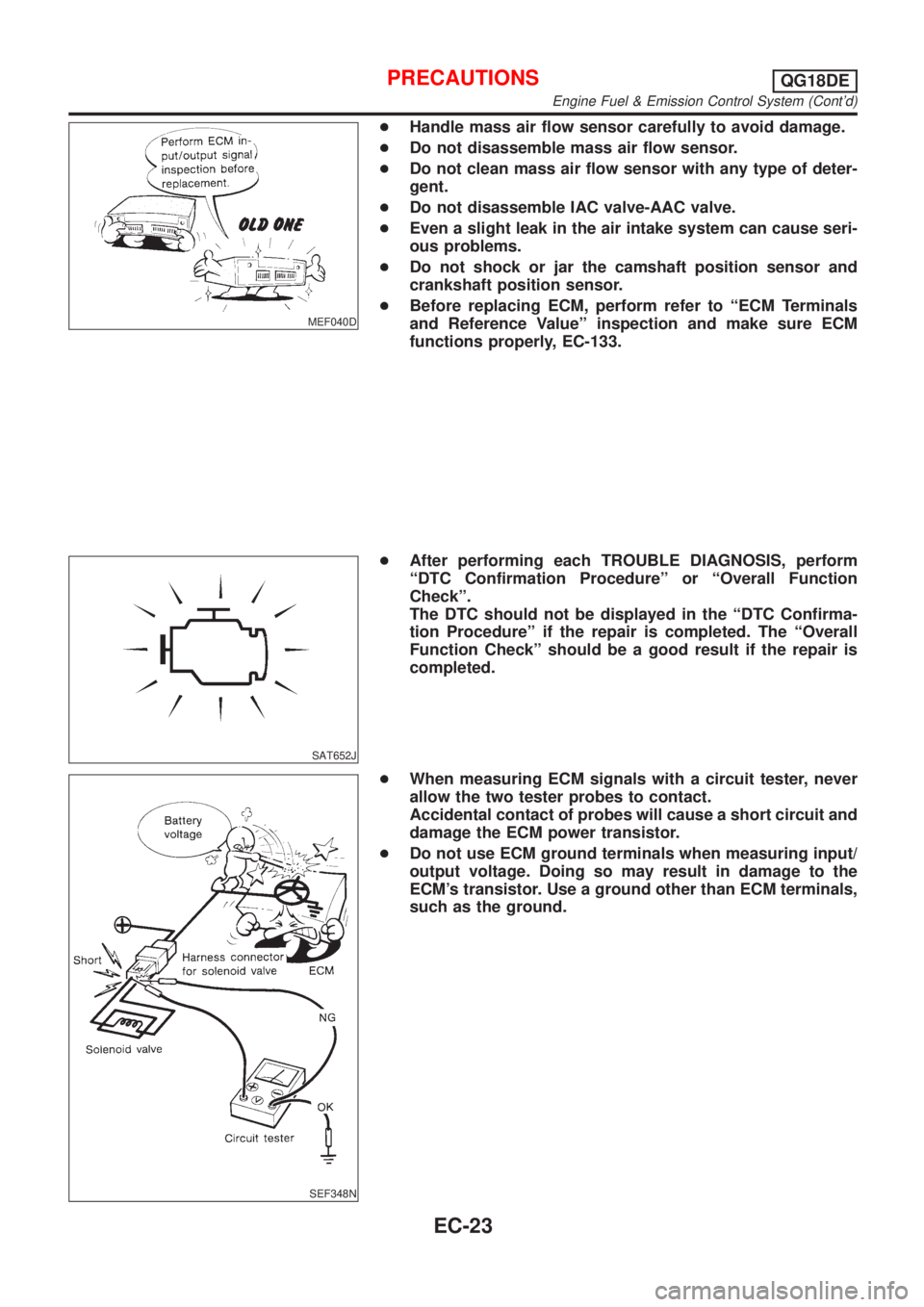
+Handle mass air flow sensor carefully to avoid damage.
+Do not disassemble mass air flow sensor.
+Do not clean mass air flow sensor with any type of deter-
gent.
+Do not disassemble IAC valve-AAC valve.
+Even a slight leak in the air intake system can cause seri-
ous problems.
+Do not shock or jar the camshaft position sensor and
crankshaft position sensor.
+Before replacing ECM, perform refer to ªECM Terminals
and Reference Valueº inspection and make sure ECM
functions properly, EC-133.
SAT652J
+After performing each TROUBLE DIAGNOSIS, perform
ªDTC Confirmation Procedureº or ªOverall Function
Checkº.
The DTC should not be displayed in the ªDTC Confirma-
tion Procedureº if the repair is completed. The ªOverall
Function Checkº should be a good result if the repair is
completed.
SEF348N
+When measuring ECM signals with a circuit tester, never
allow the two tester probes to contact.
Accidental contact of probes will cause a short circuit and
damage the ECM power transistor.
+Do not use ECM ground terminals when measuring input/
output voltage. Doing so may result in damage to the
ECM's transistor. Use a ground other than ECM terminals,
such as the ground.
PRECAUTIONSQG18DE
Engine Fuel & Emission Control System (Cont'd)
EC-23
Page 472 of 3051
SEF166Y
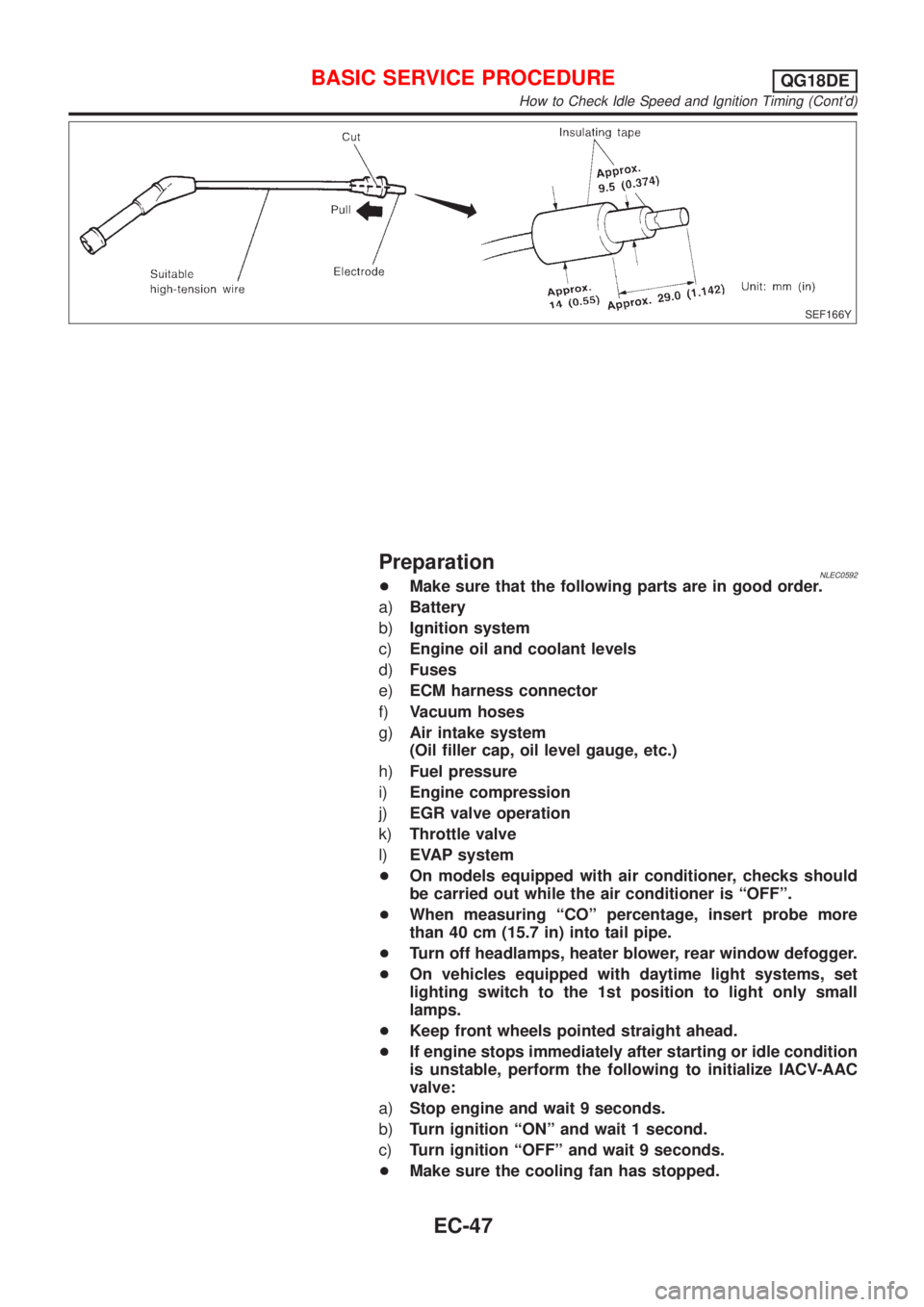
PreparationNLEC0592+Make sure that the following parts are in good order.
a)Battery
b)Ignition system
c)Engine oil and coolant levels
d)Fuses
e)ECM harness connector
f)Vacuum hoses
g)Air intake system
(Oil filler cap, oil level gauge, etc.)
h)Fuel pressure
i)Engine compression
j)EGR valve operation
k)Throttle valve
l)EVAP system
+On models equipped with air conditioner, checks should
be carried out while the air conditioner is ªOFFº.
+When measuring ªCOº percentage, insert probe more
than 40 cm (15.7 in) into tail pipe.
+Turn off headlamps, heater blower, rear window defogger.
+On vehicles equipped with daytime light systems, set
lighting switch to the 1st position to light only small
lamps.
+Keep front wheels pointed straight ahead.
+If engine stops immediately after starting or idle condition
is unstable, perform the following to initialize IACV-AAC
valve:
a)Stop engine and wait 9 seconds.
b)Turn ignition ªONº and wait 1 second.
c)Turn ignition ªOFFº and wait 9 seconds.
+Make sure the cooling fan has stopped.
BASIC SERVICE PROCEDUREQG18DE
How to Check Idle Speed and Ignition Timing (Cont'd)
EC-47
Page 475 of 3051
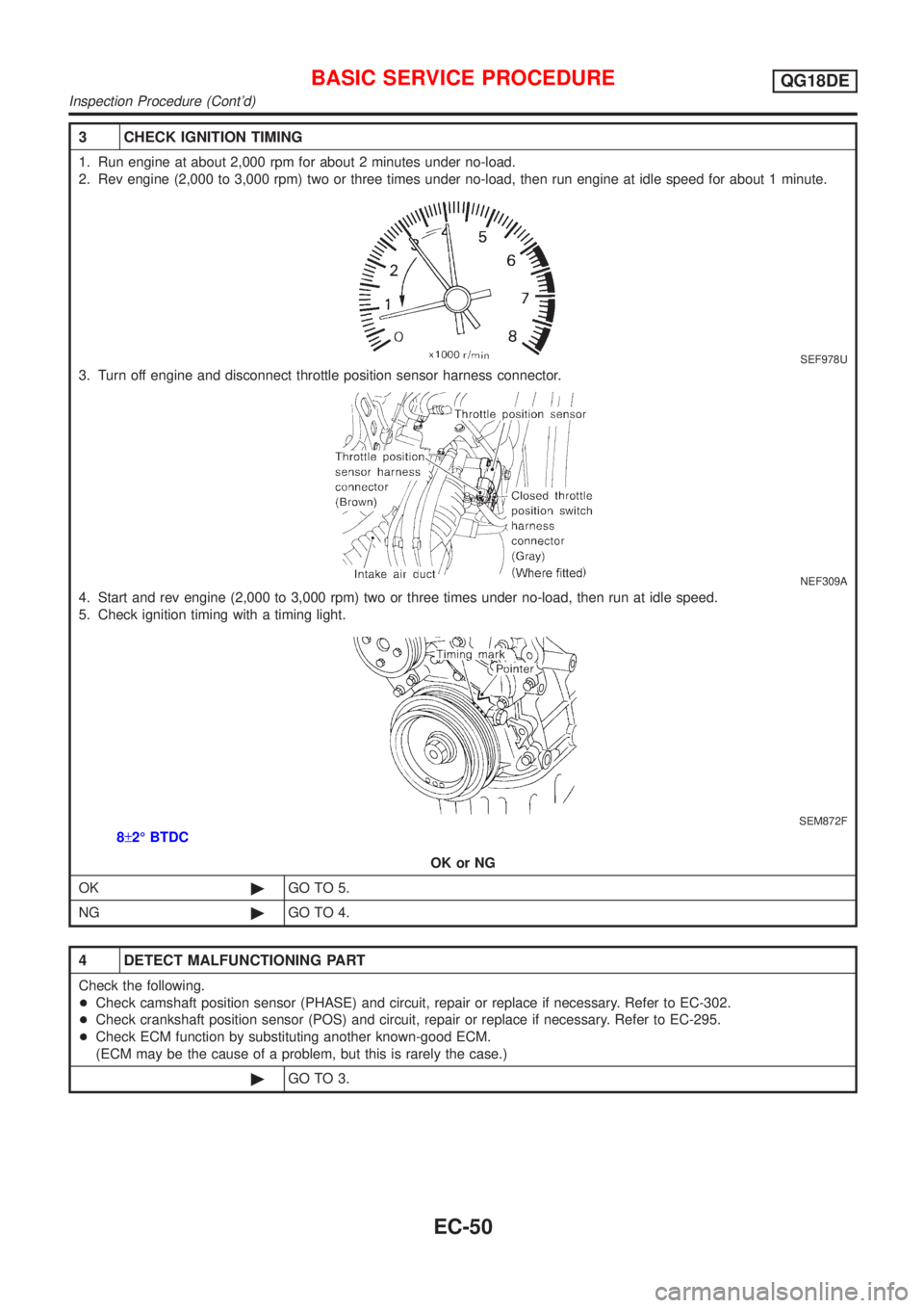
3 CHECK IGNITION TIMING
1. Run engine at about 2,000 rpm for about 2 minutes under no-load.
2. Rev engine (2,000 to 3,000 rpm) two or three times under no-load, then run engine at idle speed for about 1 minute.
SEF978U
3. Turn off engine and disconnect throttle position sensor harness connector.
NEF309A
4. Start and rev engine (2,000 to 3,000 rpm) two or three times under no-load, then run at idle speed.
5. Check ignition timing with a timing light.
SEM872F
8±2É BTDC
OK or NG
OK©GO TO 5.
NG©GO TO 4.
4 DETECT MALFUNCTIONING PART
Check the following.
+Check camshaft position sensor (PHASE) and circuit, repair or replace if necessary. Refer to EC-302.
+Check crankshaft position sensor (POS) and circuit, repair or replace if necessary. Refer to EC-295.
+Check ECM function by substituting another known-good ECM.
(ECM may be the cause of a problem, but this is rarely the case.)
©GO TO 3.
BASIC SERVICE PROCEDUREQG18DE
Inspection Procedure (Cont'd)
EC-50
Page 482 of 3051
SEF217Z
SEF454Y
SEF455Y
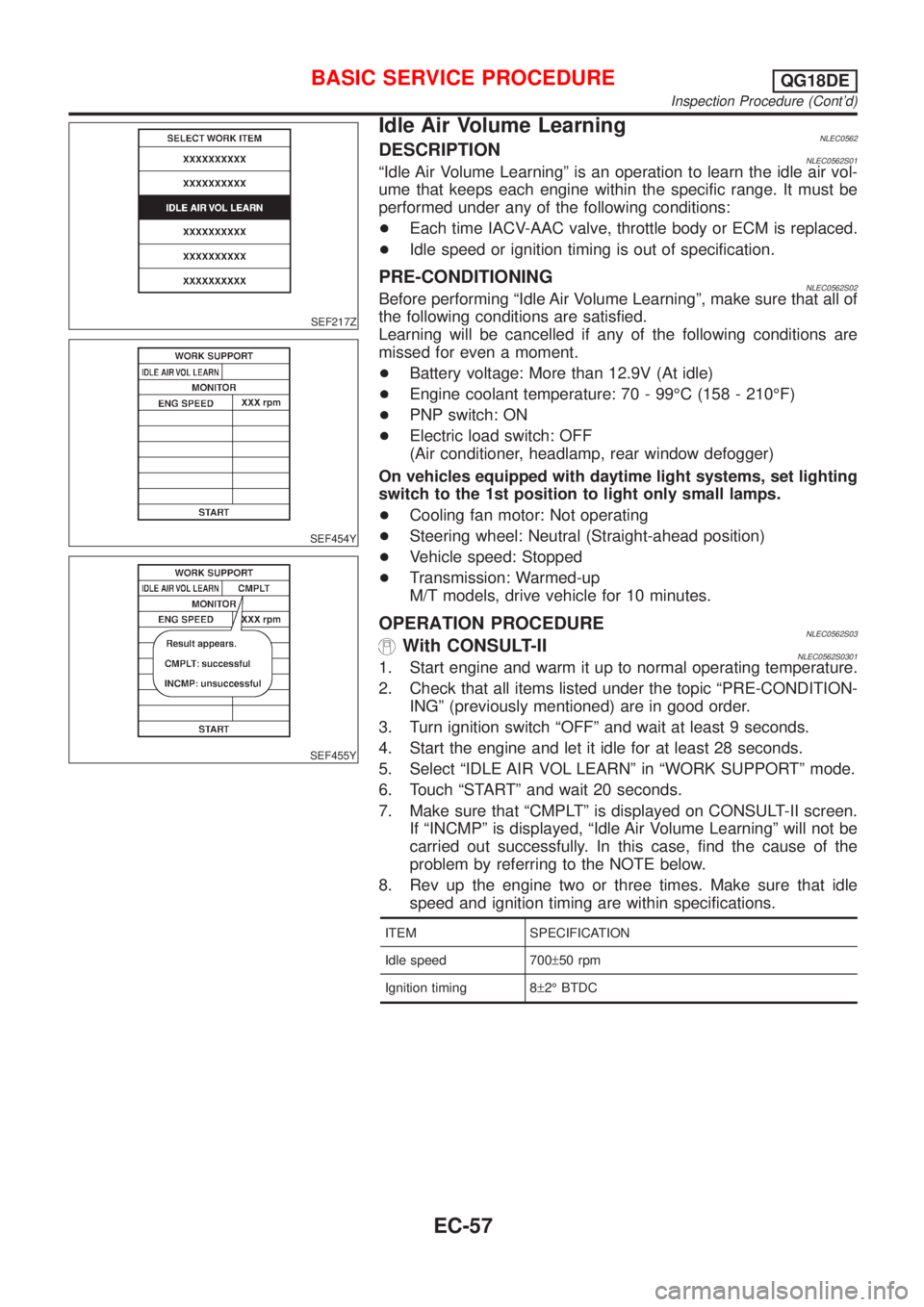
Idle Air Volume LearningNLEC0562DESCRIPTIONNLEC0562S01ªIdle Air Volume Learningº is an operation to learn the idle air vol-
ume that keeps each engine within the specific range. It must be
performed under any of the following conditions:
+Each time IACV-AAC valve, throttle body or ECM is replaced.
+Idle speed or ignition timing is out of specification.
PRE-CONDITIONINGNLEC0562S02Before performing ªIdle Air Volume Learningº, make sure that all of
the following conditions are satisfied.
Learning will be cancelled if any of the following conditions are
missed for even a moment.
+Battery voltage: More than 12.9V (At idle)
+Engine coolant temperature: 70 - 99ÉC (158 - 210ÉF)
+PNP switch: ON
+Electric load switch: OFF
(Air conditioner, headlamp, rear window defogger)
On vehicles equipped with daytime light systems, set lighting
switch to the 1st position to light only small lamps.
+Cooling fan motor: Not operating
+Steering wheel: Neutral (Straight-ahead position)
+Vehicle speed: Stopped
+Transmission: Warmed-up
M/T models, drive vehicle for 10 minutes.
OPERATION PROCEDURENLEC0562S03With CONSULT-IINLEC0562S03011. Start engine and warm it up to normal operating temperature.
2. Check that all items listed under the topic ªPRE-CONDITION-
INGº (previously mentioned) are in good order.
3. Turn ignition switch ªOFFº and wait at least 9 seconds.
4. Start the engine and let it idle for at least 28 seconds.
5. Select ªIDLE AIR VOL LEARNº in ªWORK SUPPORTº mode.
6. Touch ªSTARTº and wait 20 seconds.
7. Make sure that ªCMPLTº is displayed on CONSULT-II screen.
If ªINCMPº is displayed, ªIdle Air Volume Learningº will not be
carried out successfully. In this case, find the cause of the
problem by referring to the NOTE below.
8. Rev up the engine two or three times. Make sure that idle
speed and ignition timing are within specifications.
ITEM SPECIFICATION
Idle speed 700±50 rpm
Ignition timing 8±2É BTDC
BASIC SERVICE PROCEDUREQG18DE
Inspection Procedure (Cont'd)
EC-57