2001 NISSAN ALMERA TINO wiper
[x] Cancel search: wiperPage 1733 of 3051
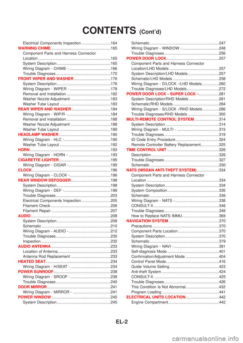
Electrical Components Inspection ...........................164
WARNING CHIME.......................................................165
Component Parts and Harness Connector
Location ...................................................................165
System Description ..................................................165
Wiring Diagram - CHIME - ......................................166
Trouble Diagnoses...................................................170
FRONT WIPER AND WASHER..................................176
System Description ..................................................176
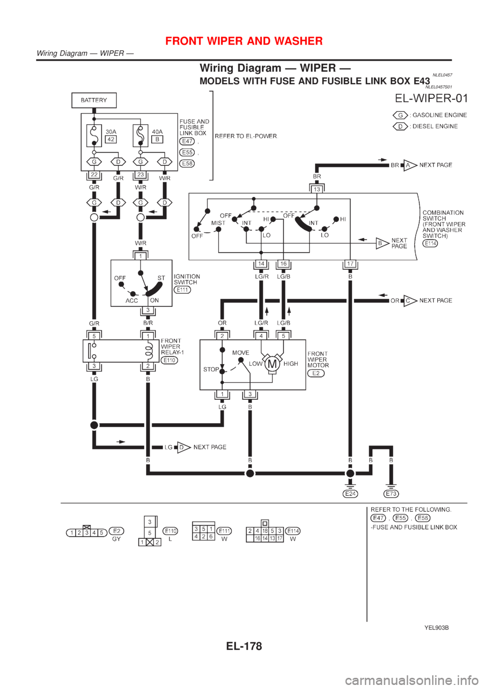
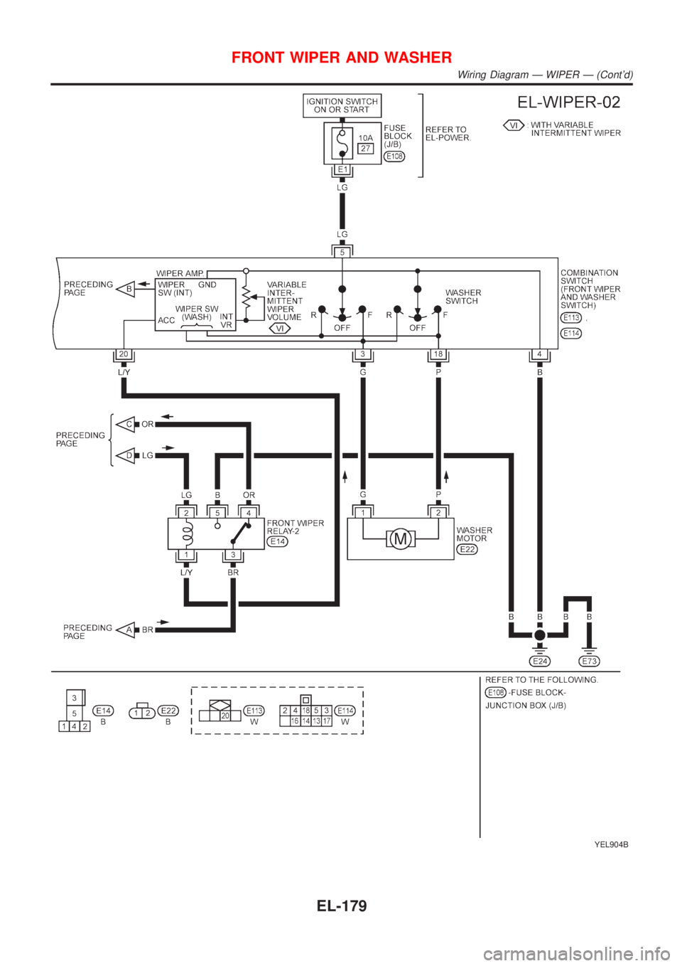
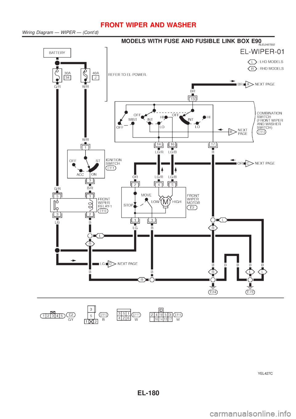
Wiring Diagram - WIPER - ......................................178
Removal and Installation .........................................182
Washer Nozzle Adjustment .....................................183
Washer Tube Layout ...............................................183
REAR WIPER AND WASHER....................................184
Wiring Diagram - WIP/R -........................................184
Removal and Installation .........................................188
Washer Nozzle Adjustment .....................................188
Washer Tube Layout ...............................................189
HEADLAMP WASHER................................................190
Wiring Diagram - HLC - ...........................................190
Washer Tube Layout ...............................................192
HORN...........................................................................193
Wiring Diagram - HORN - .......................................193
CIGARETTE LIGHTER................................................195
Wiring Diagram - CIGAR -.......................................195
CLOCK.........................................................................196
Wiring Diagram - CLOCK -......................................196
REAR WINDOW DEFOGGER.....................................198
System Description ..................................................198
Wiring Diagram - DEF - ...........................................199
Trouble Diagnoses...................................................203
Electrical Components Inspection ...........................205
Filament Check ........................................................206
Filament Repair .......................................................207
AUDIO..........................................................................208
System Description ..................................................208
Schematic ................................................................210
Wiring Diagram - AUDIO - .......................................212
Trouble Diagnoses...................................................230
Inspection.................................................................232
AUDIO ANTENNA.......................................................233
Location of Antenna .................................................233
Antenna Rod Replacement .....................................233
HEATED SEAT............................................................234
Wiring Diagram - H/SEAT - .....................................234
POWER SUNROOF.....................................................238
Wiring Diagram - SROOF - .....................................238
Trouble Diagnoses...................................................240
DOOR MIRROR...........................................................241
Wiring Diagram - MIRROR - ...................................241
POWER WINDOW.......................................................245
System Description ..................................................245Schematic ................................................................247
Wiring Diagram - WINDOW - ..................................248
Trouble Diagnoses...................................................256
POWER DOOR LOCK.................................................257
Component Parts and Harness Connector
Location/LHD Models ..............................................257
System Description/LHD Models .............................257
Schematic/LHD Models ...........................................258
Wiring Diagram - D/LOCK -/LHD Models................260
Trouble Diagnoses/LHD Models..............................272
POWER DOOR LOCK - SUPER LOCK -...................281
System Description/RHD Models ............................281
Schematic/RHD Models...........................................284
Wiring Diagram - S/LOCK -/RHD Models ...............286
Trouble Diagnoses/RHD Models .............................300
MULTI-REMOTE CONTROL SYSTEM.......................314
System Description ..................................................314
Wiring Diagram - MULTI - .......................................315
Trouble Diagnoses...................................................319
ID Code Entry Procedure ........................................324
Remote Controller Battery Replacement.................325
TIME CONTROL UNIT................................................326
Description ...............................................................326
Trouble Diagnoses...................................................327
Schematic ................................................................330
NATS (NISSAN ANTI-THEFT SYSTEM).....................334
Component Parts and Harness Connector
Location ...................................................................334
System Description ..................................................334
System Composition ................................................335
Schematic ................................................................336
Wiring Diagram - NATS -.........................................338
CONSULT-II .............................................................346
Trouble Diagnoses...................................................349
How to Replace NATS IMMU ..................................369
NAVIGATION SYSTEM...............................................370
Precautions ..............................................................370
Component Parts Location ......................................370
System Description ..................................................370
Schematic ................................................................379
Wiring Diagram - NAVI - ..........................................381
Self-diagnosis Mode ................................................401
Confirmation/Adjustment Mode ...............................404
Control Panel Mode .................................................416
Guide Volume Setting ..............................................423
Anti-theft System .....................................................424
CONSULT-II .............................................................425
Trouble Diagnoses...................................................426
This Condition Is Not Abnormal...............................432
Program Loading .....................................................441
ELECTRICAL UNITS LOCATION...............................442
Engine Compartment ...............................................442
CONTENTS(Cont'd)
EL-2
Page 1795 of 3051
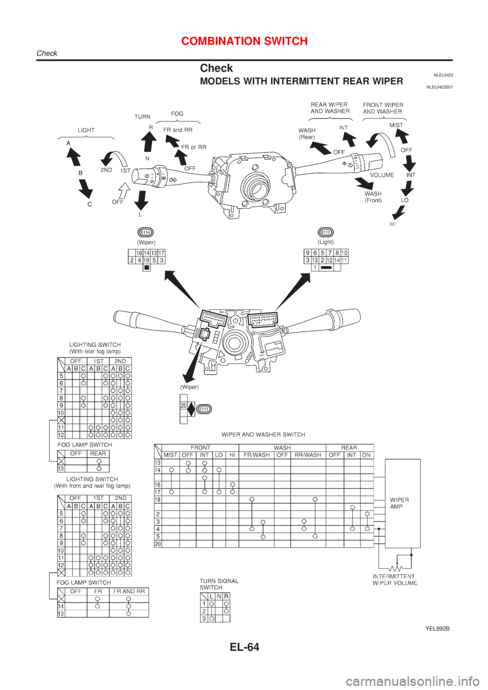
CheckNLEL0423MODELS WITH INTERMITTENT REAR WIPERNLEL0423S01
YEL992B
COMBINATION SWITCH
Check
EL-64
Page 1796 of 3051
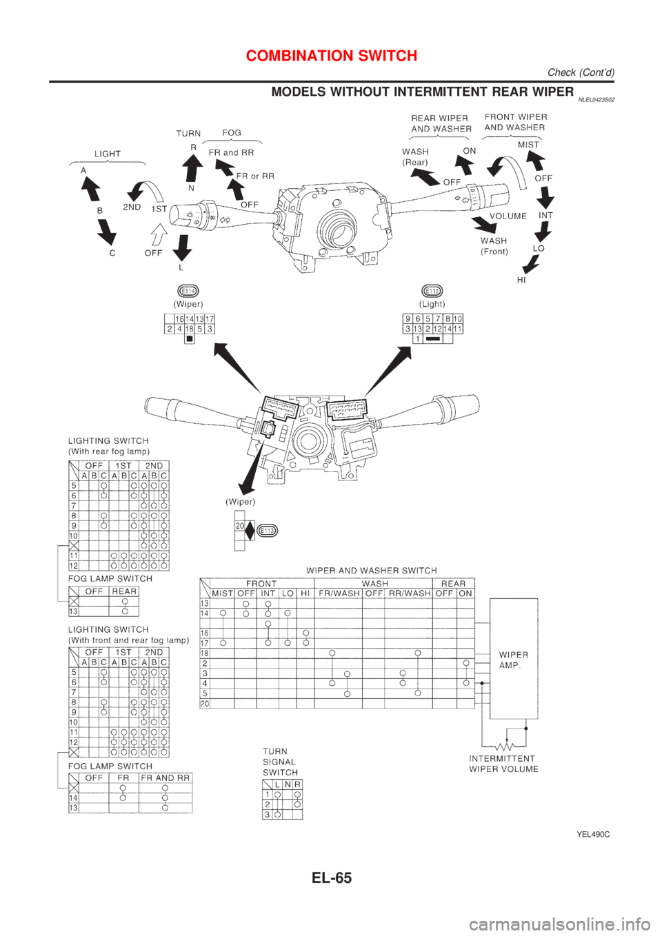
MODELS WITHOUT INTERMITTENT REAR WIPERNLEL0423S02
YEL490C
COMBINATION SWITCH
Check (Cont'd)
EL-65
Page 1907 of 3051
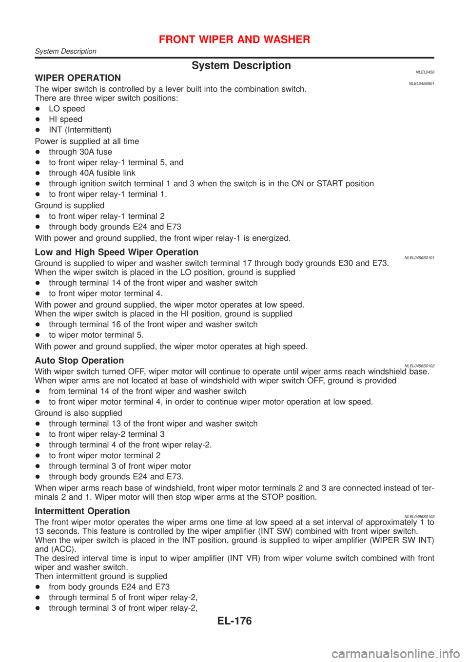
System DescriptionNLEL0456WIPER OPERATIONNLEL0456S01The wiper switch is controlled by a lever built into the combination switch.
There are three wiper switch positions:
+LO speed
+HI speed
+INT (Intermittent)
Power is supplied at all time
+through 30A fuse
+to front wiper relay-1 terminal 5, and
+through 40A fusible link
+through ignition switch terminal 1 and 3 when the switch is in the ON or START position
+to front wiper relay-1 terminal 1.
Ground is supplied
+to front wiper relay-1 terminal 2
+through body grounds E24 and E73
With power and ground supplied, the front wiper relay-1 is energized.
Low and High Speed Wiper OperationNLEL0456S0101Ground is supplied to wiper and washer switch terminal 17 through body grounds E30 and E73.
When the wiper switch is placed in the LO position, ground is supplied
+through terminal 14 of the front wiper and washer switch
+to front wiper motor terminal 4.
With power and ground supplied, the wiper motor operates at low speed.
When the wiper switch is placed in the HI position, ground is supplied
+through terminal 16 of the front wiper and washer switch
+to wiper motor terminal 5.
With power and ground supplied, the wiper motor operates at high speed.
Auto Stop OperationNLEL0456S0102With wiper switch turned OFF, wiper motor will continue to operate until wiper arms reach windshield base.
When wiper arms are not located at base of windshield with wiper switch OFF, ground is provided
+from terminal 14 of the front wiper and washer switch
+to front wiper motor terminal 4, in order to continue wiper motor operation at low speed.
Ground is also supplied
+through terminal 13 of the front wiper and washer switch
+to front wiper relay-2 terminal 3
+through terminal 4 of the front wiper relay-2.
+to front wiper motor terminal 2
+through terminal 3 of front wiper motor
+through body grounds E24 and E73.
When wiper arms reach base of windshield, front wiper motor terminals 2 and 3 are connected instead of ter-
minals 2 and 1. Wiper motor will then stop wiper arms at the STOP position.
Intermittent OperationNLEL0456S0103The front wiper motor operates the wiper arms one time at low speed at a set interval of approximately 1 to
13 seconds. This feature is controlled by the wiper amplifier (INT SW) combined with front wiper switch.
When the wiper switch is placed in the INT position, ground is supplied to wiper amplifier (WIPER SW INT)
and (ACC).
The desired interval time is input to wiper amplifier (INT VR) from wiper volume switch combined with front
wiper and washer switch.
Then intermittent ground is supplied
+from body grounds E24 and E73
+through terminal 5 of front wiper relay-2,
+through terminal 3 of front wiper relay-2,
FRONT WIPER AND WASHER
System Description
EL-176
Page 1908 of 3051
+through terminal 13 of front wiper switch and,
+through terminal 14 of front wiper switch
+to terminal 4 of front wiper motor.
The desired interval time is input
+to front wiper relay-2 terminal 1
+from terminal 20 of front wiper switch
WASHER OPERATIONNLEL0456S02With the ignition switch in the ON or START position and the lever is pulled to the WASH/F position, power
is supplied
+through 10A fuse [No. 27, located in the fuse block (J/B)]
+to front wiper switch terminal 5.
+through front wiper switch terminal 3
+to front washer motor terminal 1.
When the lever is pulled to the WASH/F position, ground is supplied
+from body grounds E24 and E73
+through terminal 4 of the front wiper switch
+through terminal 18 of the front wiper switch
+to front washer motor terminal 2.
With power and ground supplied, the washer motor operates.
When the lever is pulled to the WASH position for one second or more, the wiper motor operates at low speed
for approximately 3 seconds to clean windshield. This feature is controlled by the wiper amplifier in the same
manner as the intermittent operation.
FRONT WIPER AND WASHER
System Description (Cont'd)
EL-177
Page 1909 of 3051
Wiring Diagram Ð WIPER ÐNLEL0457MODELS WITH FUSE AND FUSIBLE LINK BOX E43NLEL0457S01
YEL903B
FRONT WIPER AND WASHER
Wiring Diagram Ð WIPER Ð
EL-178
Page 1910 of 3051
YEL904B
FRONT WIPER AND WASHER
Wiring Diagram Ð WIPER Ð (Cont'd)
EL-179
Page 1911 of 3051
MODELS WITH FUSE AND FUSIBLE LINK BOX E90NLEL0457S02
YEL427C
FRONT WIPER AND WASHER
Wiring Diagram Ð WIPER Ð (Cont'd)
EL-180