2001 NISSAN ALMERA TINO flat tire
[x] Cancel search: flat tirePage 309 of 3051

3 CHECK WHEEL SENSOR CIRCUIT
1. Disconnect control unit connector.
2. Check resistance between control unit connector terminals.
Code No. 21 or 22 (Front RH wheel)
Terminals 4 and 5
Code No. 25 or 26 (Front LH wheel)
Terminals 6 and 7
Resistance: 1.44 - 1.76 kΩ
Code No. 31 or 32 (Rear RH wheel)
Terminals 1 and 3
Code No. 35 or 36 (Rear LH wheel)
Terminals 8 and 9
Resistance: 1.05 - 1.35 kΩ
SBR477EC
Is resistance 1.44 - 1.76 kΩ(FR) or 1.05 - 1.35 kΩ(RR)?
Ye s©GO TO 5.
No©GO TO 4.
4 CHECK WHEEL SENSOR
Check resistance of each sensor. (See NOTE.)
Resistance: 1.44 - 1.76 kΩ(FR)
Resistance: 1.05 - 1.35 kΩ(RR)
NBR378
Is resistance 1.44 - 1.76 kΩ(FR) or 1.05 - 1.35 kΩ(RR)?
Ye s©Repair harness and connectors between control unit connector and wheel sensor con-
nector.
No©Replace wheel sensor.
5 CHECK TIRE
Check for inflation pressure, wear and size of each tire.
Are tire pressure and size correct and is tire wear within specifications?
Ye s©GO TO 6.
No©Adjust tire pressure or replace tire(s).
TROUBLE DIAGNOSES FOR SELF-DIAGNOSTIC ITEMSABS
Wheel Sensor or Rotor (Cont’d)
BR-72
Page 1803 of 3051
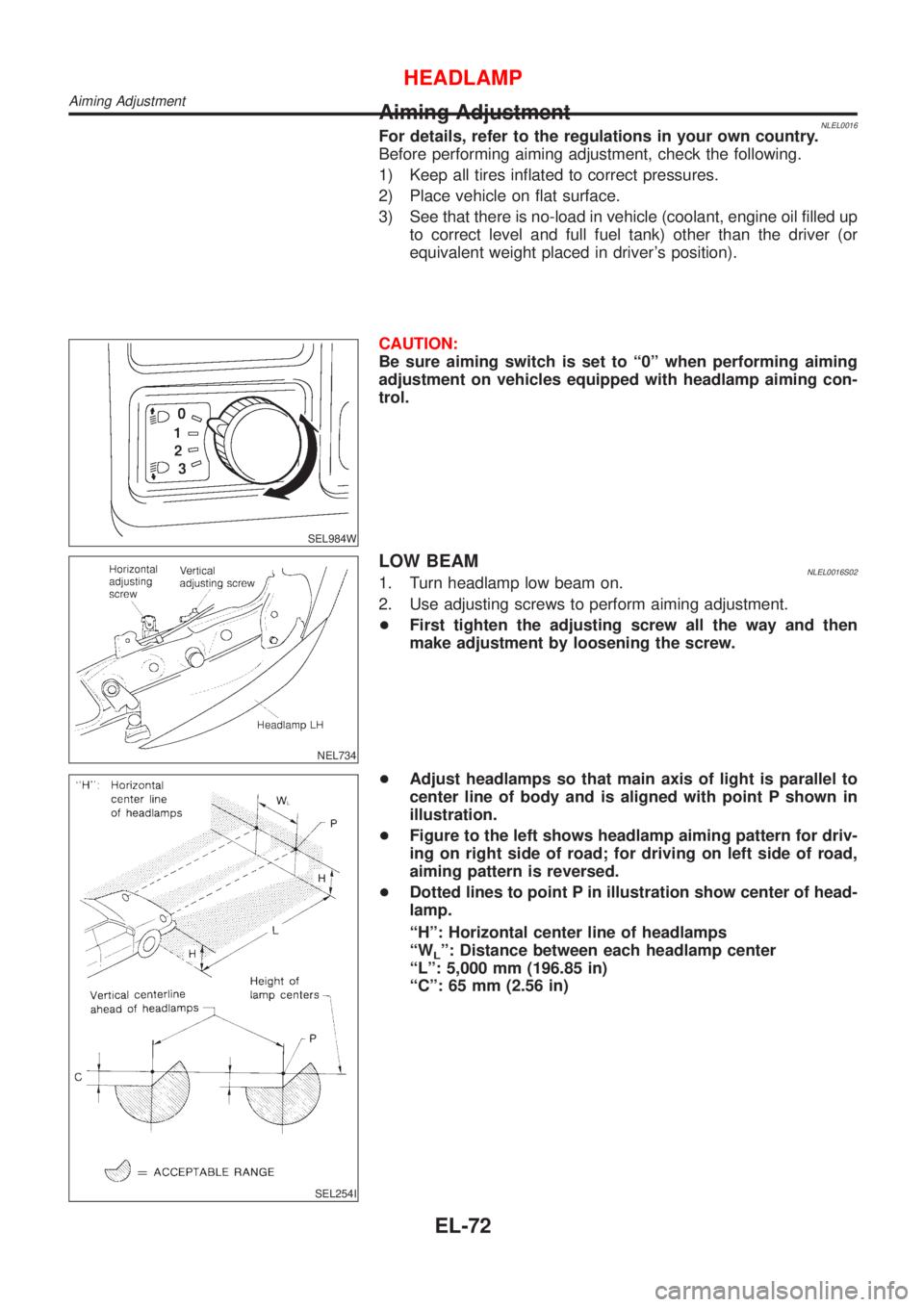
Aiming AdjustmentNLEL0016For details, refer to the regulations in your own country.
Before performing aiming adjustment, check the following.
1) Keep all tires inflated to correct pressures.
2) Place vehicle on flat surface.
3) See that there is no-load in vehicle (coolant, engine oil filled up
to correct level and full fuel tank) other than the driver (or
equivalent weight placed in driver's position).
SEL984W
CAUTION:
Be sure aiming switch is set to ª0º when performing aiming
adjustment on vehicles equipped with headlamp aiming con-
trol.
NEL734
LOW BEAMNLEL0016S021. Turn headlamp low beam on.
2. Use adjusting screws to perform aiming adjustment.
+First tighten the adjusting screw all the way and then
make adjustment by loosening the screw.
SEL254I
+Adjust headlamps so that main axis of light is parallel to
center line of body and is aligned with point P shown in
illustration.
+Figure to the left shows headlamp aiming pattern for driv-
ing on right side of road; for driving on left side of road,
aiming pattern is reversed.
+Dotted lines to point P in illustration show center of head-
lamp.
ªHº: Horizontal center line of headlamps
ªW
Lº: Distance between each headlamp center
ªLº: 5,000 mm (196.85 in)
ªCº: 65 mm (2.56 in)
HEADLAMP
Aiming Adjustment
EL-72
Page 1829 of 3051
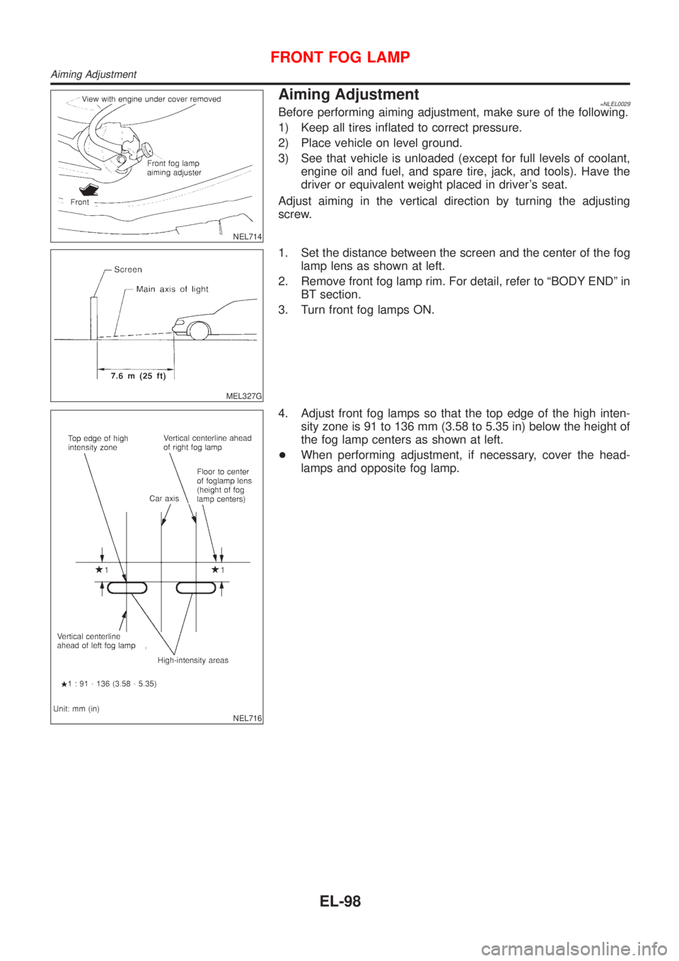
NEL714
Aiming Adjustment=NLEL0029Before performing aiming adjustment, make sure of the following.
1) Keep all tires inflated to correct pressure.
2) Place vehicle on level ground.
3) See that vehicle is unloaded (except for full levels of coolant,
engine oil and fuel, and spare tire, jack, and tools). Have the
driver or equivalent weight placed in driver's seat.
Adjust aiming in the vertical direction by turning the adjusting
screw.
MEL327G
1. Set the distance between the screen and the center of the fog
lamp lens as shown at left.
2. Remove front fog lamp rim. For detail, refer to ªBODY ENDº in
BT section.
3. Turn front fog lamps ON.
NEL716
4. Adjust front fog lamps so that the top edge of the high inten-
sity zone is 91 to 136 mm (3.58 to 5.35 in) below the height of
the fog lamp centers as shown at left.
+When performing adjustment, if necessary, cover the head-
lamps and opposite fog lamp.
FRONT FOG LAMP
Aiming Adjustment
EL-98
Page 2907 of 3051

Precautions
SUPPLEMENTAL RESTRAINT SYSTEM (SRS)“AIR BAG”AND“SEAT BELT
PRE-TENSIONER”
NLRS0006The Supplemental Restraint System such as“AIR BAG”and“SEAT BELT PRE-TENSIONER”used along with
a seat belt, helps to reduce the risk or severity of injury to the driver and front passenger for certain types of
collision. The SRS composition which is available to NISSAN MODEL V10 is as follows (The composition var-
ies according to the destination and optional equipment.):
+For a frontal collision
The Supplemental Restraint System consists of driver air bag module (located in the center of the steer-
ing wheel), front passenger air bag module (located on the instrument panel on passenger side), front seat
belt pre-tensioners, a diagnosis sensor unit, warning lamp, wiring harness and spiral cable.
+For a side collision
The Supplemental Restraint System consists of front side air bag module (located in the outer side of front
seat), side air bag (satellite) sensor, diagnosis sensor unit (one of components of air bags for a frontal
collision), wiring harness, warning lamp (one of components of air bags for a frontal collision).
WARNING:
+To avoid rendering the SRS inoperative, which could increase the risk of personal injury or death
in the event of a collision which would result in air bag inflation, all maintenance should be per-
formed by an authorized NISSAN dealer.
+Improper maintenance, including incorrect removal and installation of the SRS, can lead to per-
sonal injury caused by unintentional activation of the system.
+Do not use electrical test equipment on any circuit related to the SRS unless instructed to in this
Service Manual. Spiral cable and wiring harnesses covered with yellow insulation tape either just
before the harness connectors or for the complete harness are related to the SRS.
PRECAUTIONS FOR SRS“AIR BAG”AND“SEAT BELT PRE-TENSIONER”SERVICENLRS0007+Do not use electrical test equipment to check SRS circuits unless instructed to in this Service Manual.
+Before servicing the SRS, turn ignition switch“OFF”, disconnect both battery cables and wait at least 3
minutes.
For approximately 3 minutes after the cables are removed, it is still possible for the air bag and seat belt
pre-tensioner to deploy. Therefore, do not work on any SRS connectors or wires until at least 3 minutes
have passed.
+Diagnosis sensor unit must always be installed with their arrow marks“⇐”pointing towards the front of
the vehicle for proper operation. Also check diagnosis sensor unit for cracks, deformities or rust before
installation and replace as required.
+The spiral cable must be aligned with the neutral position since its rotations are limited. Do not attempt to
turn steering wheel or column after removal of steering gear.
+Handle air bag module carefully. Always place driver and front passenger air bag modules with the pad
side facing upward and place front side air bag module (built-in type) standing with stud bolt side setting
bottom.
+Conduct self-diagnosis to check entire SRS for proper function after replacing any components.
+After air bag inflates, the front instrument panel assembly should be replaced if damaged.
WIRING DIAGRAMS AND TROUBLE DIAGNOSISNLRS0008When you read wiring diagrams, refer to the following:
+GI-11,“HOW TO READ WIRING DIAGRAMS”
+EL-10,“POWER SUPPLY ROUTING”for power distribution circuit
When you perform trouble diagnosis, refer to the following:
+GI-32,“HOW TO FOLLOW TEST GROUPS IN TROUBLE DIAGNOSIS”
+GI-21,“HOW TO PERFORM EFFICIENT DIAGNOSES FOR AN ELECTRICAL INCIDENT”
SUPPLEMENTAL RESTRAINT SYSTEM (SRS)
Precautions
RS-16
Page 2919 of 3051

SBF814E
+Replace front passenger air bag module if it has been
dropped or sustained an impact.
+Do not expose the front passenger air bag module to tem-
peratures exceeding 90°C (194°F).
+Do not allow oil, grease or water to come in contact with
the front passenger air bag module.
+After front passenger air bag inflates, the front instrument
panel assembly should be replaced if damaged.
NRS109
INSTALLATIONNLRS0019CAUTION:
+Always work from the side of or under front passenger air
bag module.
1. Install front passenger air bag module on the steering member
and secure with new special bolts.
+Ensure harness is not caught between rear of front passenger
air bag module and steering member.
NRS107
2. Put the front passenger air bag module connector and air bag
harness connector through the opening of the glove box cover.
3. Install glove box cover.
4. Attach the front passenger air bag module connector to the
connector cover lid.
5. Install glove box assembly. (Glove box is open.)
Refer to BT-22,“INSTRUMENT PANEL ASSEMBLY”for
details.
NRS111
6. Connect front passenger air bag module connector to air bag
harness connector.
7. Close the connector cover lid.
8. Close glove box.
9. Connect both battery cable.
10. Conduct self diagnosis to ensure entire SRS operates properly.
(use CONSULT-II or warning lamp check.)
SRS866
Front Side Air Bag Module
REMOVALNLRS0059CAUTION:
+Before servicing SRS, turn the ignition switch OFF, dis-
connect both battery cables and wait at least 3 minutes.
+Always work from the rear of the front side air bag mod-
ule.
1. Open the seatback zipper.
2. Disconnect front side air bag module connector.
SUPPLEMENTAL RESTRAINT SYSTEM (SRS)
Front Passenger Air Bag Module (Cont’d)
RS-28
Page 3003 of 3051
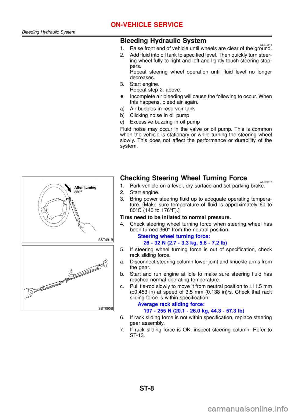
Bleeding Hydraulic SystemNLST00141. Raise front end of vehicle until wheels are clear of the ground.
2. Add fluid into oil tank to specified level. Then quickly turn steer-
ing wheel fully to right and left and lightly touch steering stop-
pers.
Repeat steering wheel operation until fluid level no longer
decreases.
3. Start engine.
Repeat step 2. above.
+Incomplete air bleeding will cause the following to occur. When
this happens, bleed air again.
a) Air bubbles in reservoir tank
b) Clicking noise in oil pump
c) Excessive buzzing in oil pump
Fluid noise may occur in the valve or oil pump. This is common
when the vehicle is stationary or while turning the steering wheel
slowly. This does not affect the performance or durability of the
system.
SST491B
SST090B
Checking Steering Wheel Turning ForceNLST00151. Park vehicle on a level, dry surface and set parking brake.
2. Start engine.
3. Bring power steering fluid up to adequate operating tempera-
ture. [Make sure temperature of fluid is approximately 60 to
80°C (140 to 176°F).]
Tires need to be inflated to normal pressure.
4. Check steering wheel turning force when steering wheel has
been turned 360°from the neutral position.
Steering wheel turning force:
26 - 32 N (2.7 - 3.3 kg, 5.8 - 7.2 lb)
5. If steering wheel turning force is out of specification, check
rack sliding force.
a. Disconnect steering column lower joint and knuckle arms from
the gear.
b. Start and run engine at idle to make sure steering fluid has
reached normal operating temperature.
c. Pull tie-rod slowly to move it from neutral position to±11.5 mm
(±0.453 in) at speed of 3.5 mm (0.138 in)/s. Check that rack
sliding force is within specification.
Average rack sliding force:
197 - 255 N (20.1 - 26.0 kg, 44.3 - 57.3 lb)
6. If rack sliding force is not within specification, replace steering
gear assembly.
7. If rack sliding force is OK, inspect steering column. Refer to
ST-13.
ON-VEHICLE SERVICE
Bleeding Hydraulic System
ST-8
Page 3029 of 3051
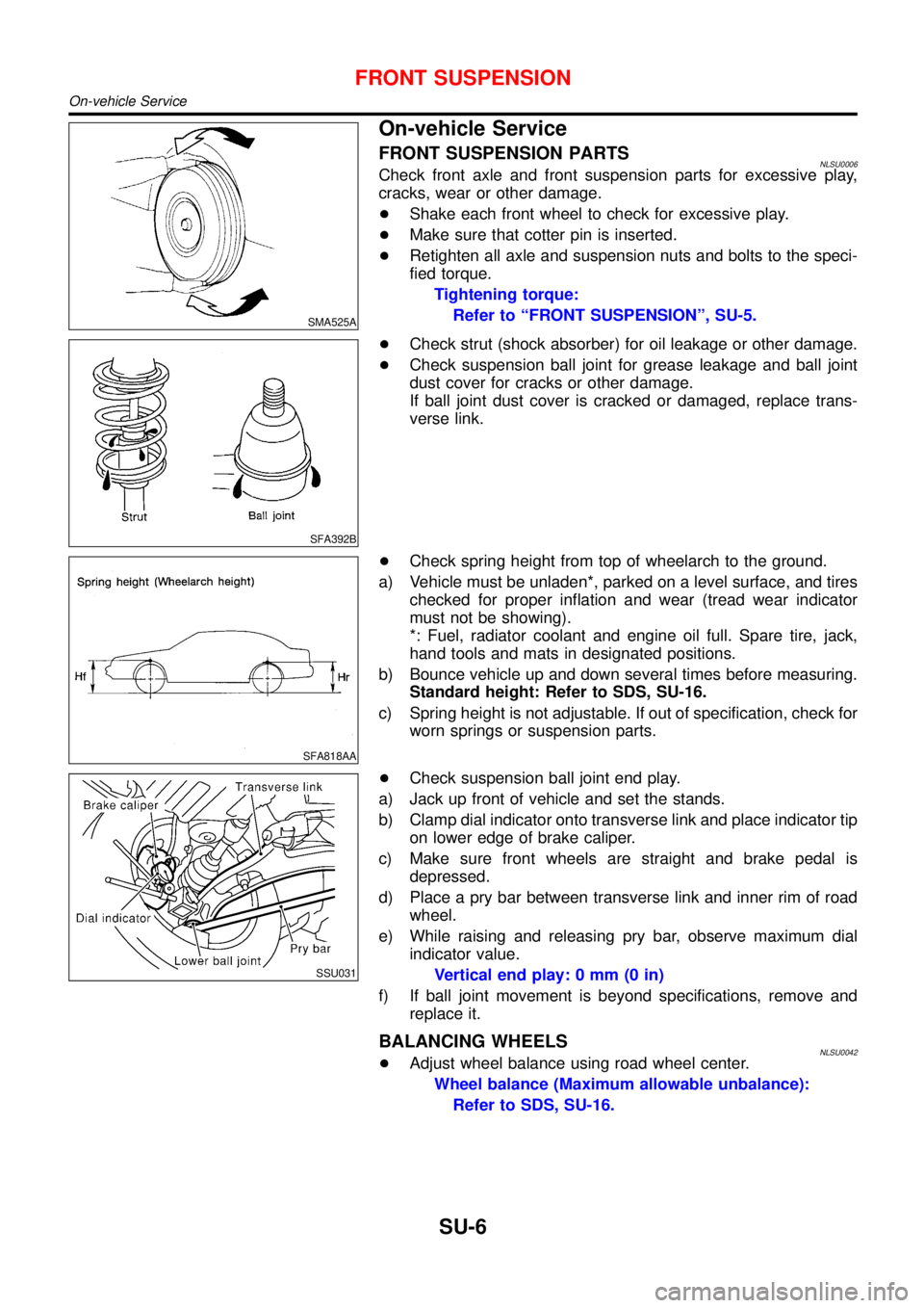
SMA525A
On-vehicle Service
FRONT SUSPENSION PARTSNLSU0006Check front axle and front suspension parts for excessive play,
cracks, wear or other damage.
+Shake each front wheel to check for excessive play.
+Make sure that cotter pin is inserted.
+Retighten all axle and suspension nuts and bolts to the speci-
fied torque.
Tightening torque:
Refer to “FRONT SUSPENSION”, SU-5.
SFA392B
+Check strut (shock absorber) for oil leakage or other damage.
+Check suspension ball joint for grease leakage and ball joint
dust cover for cracks or other damage.
If ball joint dust cover is cracked or damaged, replace trans-
verse link.
SFA818AA
+Check spring height from top of wheelarch to the ground.
a) Vehicle must be unladen*, parked on a level surface, and tires
checked for proper inflation and wear (tread wear indicator
must not be showing).
*: Fuel, radiator coolant and engine oil full. Spare tire, jack,
hand tools and mats in designated positions.
b) Bounce vehicle up and down several times before measuring.
Standard height: Refer to SDS, SU-16.
c) Spring height is not adjustable. If out of specification, check for
worn springs or suspension parts.
SSU031
+Check suspension ball joint end play.
a) Jack up front of vehicle and set the stands.
b) Clamp dial indicator onto transverse link and place indicator tip
on lower edge of brake caliper.
c) Make sure front wheels are straight and brake pedal is
depressed.
d) Place a pry bar between transverse link and inner rim of road
wheel.
e) While raising and releasing pry bar, observe maximum dial
indicator value.
Vertical end play: 0 mm (0 in)
f) If ball joint movement is beyond specifications, remove and
replace it.
BALANCING WHEELSNLSU0042+Adjust wheel balance using road wheel center.
Wheel balance (Maximum allowable unbalance):
Refer to SDS, SU-16.
FRONT SUSPENSION
On-vehicle Service
SU-6
Page 3030 of 3051
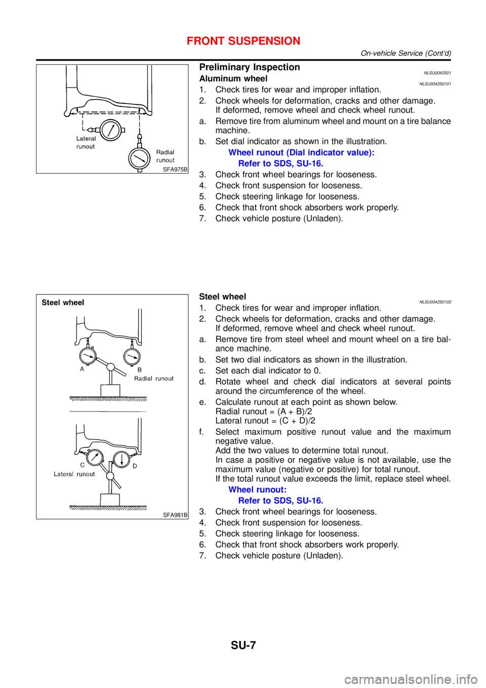
SFA975B
Preliminary InspectionNLSU0042S01Aluminum wheelNLSU0042S01011. Check tires for wear and improper inflation.
2. Check wheels for deformation, cracks and other damage.
If deformed, remove wheel and check wheel runout.
a. Remove tire from aluminum wheel and mount on a tire balance
machine.
b. Set dial indicator as shown in the illustration.
Wheel runout (Dial indicator value):
Refer to SDS, SU-16.
3. Check front wheel bearings for looseness.
4. Check front suspension for looseness.
5. Check steering linkage for looseness.
6. Check that front shock absorbers work properly.
7. Check vehicle posture (Unladen).
SFA981B
Steel wheelNLSU0042S01021. Check tires for wear and improper inflation.
2. Check wheels for deformation, cracks and other damage.
If deformed, remove wheel and check wheel runout.
a. Remove tire from steel wheel and mount wheel on a tire bal-
ance machine.
b. Set two dial indicators as shown in the illustration.
c. Set each dial indicator to 0.
d. Rotate wheel and check dial indicators at several points
around the circumference of the wheel.
e. Calculate runout at each point as shown below.
Radial runout = (A + B)/2
Lateral runout = (C + D)/2
f. Select maximum positive runout value and the maximum
negative value.
Add the two values to determine total runout.
In case a positive or negative value is not available, use the
maximum value (negative or positive) for total runout.
If the total runout value exceeds the limit, replace steel wheel.
Wheel runout:
Refer to SDS, SU-16.
3. Check front wheel bearings for looseness.
4. Check front suspension for looseness.
5. Check steering linkage for looseness.
6. Check that front shock absorbers work properly.
7. Check vehicle posture (Unladen).
FRONT SUSPENSION
On-vehicle Service (Cont’d)
SU-7