2001 NISSAN ALMERA TINO mirror
[x] Cancel search: mirrorPage 332 of 3051
BODY & TRIM
SECTION
BT
CONTENTS
PRECAUTIONS...............................................................3
Service Notice..............................................................3
Supplemental Restraint System (SRS)²AIR
BAG²and²SEAT BELT PRE-TENSIONER²...............3
CLIP AND FASTENER....................................................4
Description ...................................................................4
CHASSIS AND BODY MAINTENANCE.........................6
Checking Body Corrosion ............................................6
BODY FRONT END.........................................................7
Removal and Installation .............................................7
FRONT BUMPER ASSEMBLY....................................7
BODY REAR END AND OPENER................................10
Removal and Installation ...........................................10
REAR BUMPER ASSEMBLY....................................10
DOOR.............................................................................13
Adjustment .................................................................13
STRIKER ADJUSTMENT..........................................13
Front Door Glass .......................................................14
FRONT DOOR GLASS AND REGULATOR................14
Front Door Limit Switch Reset (Driver side only)......15
RESET CONDITIONS..............................................15
RESET PROCEDURES............................................15
Rear Door Glass ........................................................16
REAR DOOR GLASS AND REGULATOR..................16
Front Door Lock .........................................................18
OUTSIDE HANDLE ROD ADJUSTMENT...................18
REMOVAL...............................................................18
Rear Door Lock .........................................................20
OUTSIDE HANDLE ROD ADJUSTMENT...................20
REMOVAL...............................................................21
INSTRUMENT PANEL ASSEMBLY.............................22
Removal and Installation ...........................................22
SIDE AND FLOOR TRIM...............................................28
Removal and Installation ...........................................28
LUGGAGE ROOM TRIM...............................................31
Removal and Installation ...........................................31
DOOR TRIM...................................................................32
Removal and Installation ...........................................32ROOF TRIM...................................................................35
Removal and Installation ...........................................35
BACK DOOR TRIM.......................................................37
Removal and Installation ...........................................37
EXTERIOR.....................................................................38
Removal and Installation ...........................................38
FRONT SEAT................................................................46
Removal and Installation ...........................................46
MANUAL SEAT........................................................47
Heated Seat ...............................................................48
Active Head Restraint ................................................48
OPERATION OUTLINE............................................48
REAR SEAT...................................................................49
Removal and Installation ...........................................49
REAR OUTSIDE SEAT.............................................49
REAR CENTER SEAT..............................................50
SUNROOF......................................................................51
Adjustment .................................................................51
Removal .....................................................................51
Trouble Diagnoses.....................................................55
DIAGNOSTIC TABLE................................................55
WIND DEFLECTOR (WHERE FITTED)......................55
ADJUSTMENT.........................................................56
DRAIN HOSES........................................................57
WEATHERSTRIP.....................................................57
LINK AND WIRE ASSEMBLY....................................58
WINDSHIELD AND WINDOWS....................................59
Removal and Installation ...........................................59
REMOVAL...............................................................59
INSTALLATION........................................................59
WINDSHIELD..........................................................60
SIDE WINDOW........................................................61
BACK DOOR WINDOW............................................62
DOOR MIRROR.............................................................63
Removal and Installation ...........................................63
REAR VIEW MIRROR...................................................64
Removal and Installation ...........................................64
REMOVAL...............................................................64
Page 394 of 3051
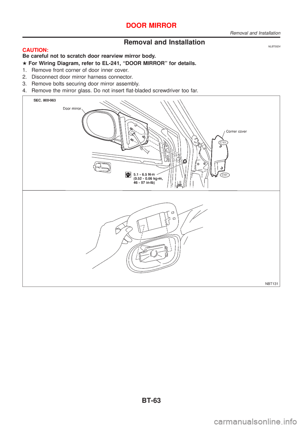
Removal and InstallationNLBT0024CAUTION:
Be careful not to scratch door rearview mirror body.
HFor Wiring Diagram, refer to EL-241, ªDOOR MIRRORº for details.
1. Remove front corner of door inner cover.
2. Disconnect door mirror harness connector.
3. Remove bolts securing door mirror assembly.
4. Remove the mirror glass. Do not insert flat-bladed screwdriver too far.
NBT131
DOOR MIRROR
Removal and Installation
BT-63
Page 395 of 3051
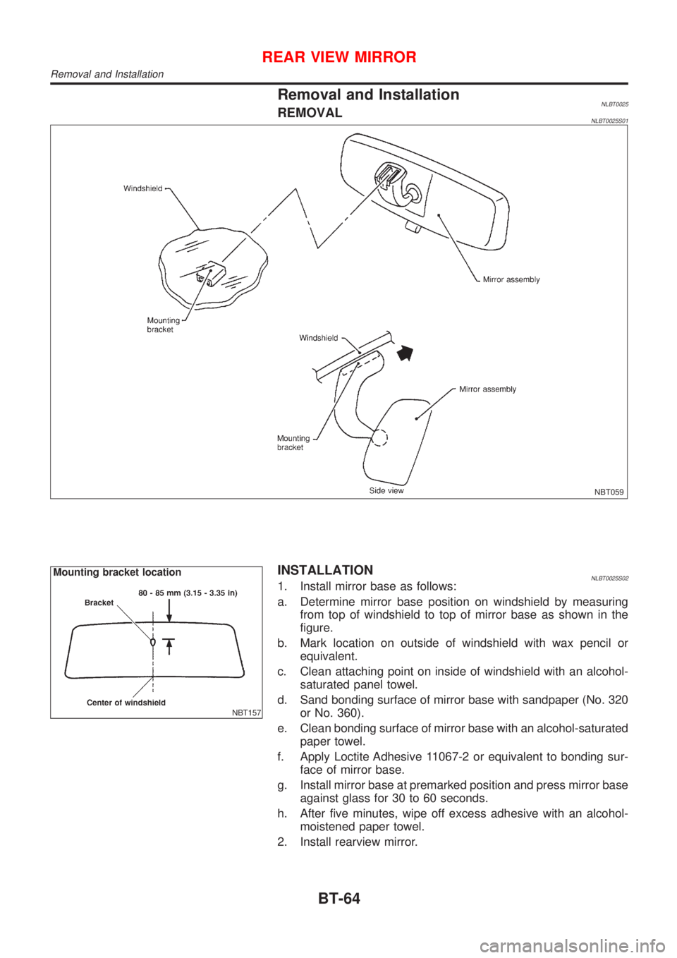
Removal and InstallationNLBT0025REMOVALNLBT0025S01
NBT059
NBT157
INSTALLATIONNLBT0025S021. Install mirror base as follows:
a. Determine mirror base position on windshield by measuring
from top of windshield to top of mirror base as shown in the
figure.
b. Mark location on outside of windshield with wax pencil or
equivalent.
c. Clean attaching point on inside of windshield with an alcohol-
saturated panel towel.
d. Sand bonding surface of mirror base with sandpaper (No. 320
or No. 360).
e. Clean bonding surface of mirror base with an alcohol-saturated
paper towel.
f. Apply Loctite Adhesive 11067-2 or equivalent to bonding sur-
face of mirror base.
g. Install mirror base at premarked position and press mirror base
against glass for 30 to 60 seconds.
h. After five minutes, wipe off excess adhesive with an alcohol-
moistened paper towel.
2. Install rearview mirror.
REAR VIEW MIRROR
Removal and Installation
BT-64
Page 1732 of 3051
ELECTRICAL SYSTEM
SECTION
EL
CONTENTS
PRECAUTIONS...............................................................4
Supplemental Restraint System (SRS)²AIR
BAG²and²SEAT BELT PRE-TENSIONER²...............4
Wiring Diagrams and Trouble Diagnosis .....................4
HARNESS CONNECTOR................................................5
Description ...................................................................5
STANDARDIZED RELAY................................................7
Description ...................................................................7
POWER SUPPLY ROUTING...........................................9
Schematic ..................................................................10
Wiring Diagram - POWER - (Models with fuse
and fusible link box E43) ...........................................14
Wiring Diagram - POWER - (Models with fuse
and fusible link box E90) ...........................................24
Inspection...................................................................32
GROUND........................................................................33
Ground Distribution (Models with fuse and fusible
link box E43) ..............................................................33
Ground Distribution (Models with fuse and fusible
link box E90) ..............................................................48
COMBINATION SWITCH..............................................64
Check .........................................................................64
Replacement ..............................................................66
STEERING SWITCH......................................................67
Check .........................................................................67
HEADLAMP...................................................................69
Wiring Diagram - H/LAMP -.......................................69
Trouble Diagnoses.....................................................71
Bulb Replacement .....................................................71
Aiming Adjustment .....................................................72
HEADLAMP - DAYTIME LIGHT SYSTEM -.................73
System Description ....................................................73
Schematic ..................................................................74
Wiring Diagram - DTRL - ...........................................75
Trouble Diagnoses.....................................................81
Bulb Replacement .....................................................81
Aiming Adjustment .....................................................82
HEADLAMP - HEADLAMP AIMING CONTROL -........83
Wiring Diagram - H/AIM - ..........................................83PARKING, LICENSE AND TAIL LAMPS.....................87
Wiring Diagram - TAIL/L - ..........................................87
STOP LAMP..................................................................91
Wiring Diagram - STOP/L - .......................................91
BACK-UP LAMP............................................................93
Wiring Diagram - BACK/L - .......................................93
FRONT FOG LAMP.......................................................95
Wiring Diagram - F/FOG - .........................................95
Bulb Replacement .....................................................97
Aiming Adjustment .....................................................98
REAR FOG LAMP.........................................................99
Wiring Diagram - R/FOG -.........................................99
TURN SIGNAL AND HAZARD WARNING LAMPS...101
System Description ..................................................101
Wiring Diagram - TURN - ........................................102
Trouble Diagnoses...................................................106
ILLUMINATION............................................................107
Schematic ................................................................107
Wiring Diagram - ILL - .............................................109
INTERIOR ROOM LAMP............................................. 116
System Description .................................................. 116
Wiring Diagram - ROOM/L - .................................... 118
Trouble Diagnoses...................................................122
VANITY MIRROR AND LUGGAGE ROOM LAMPS..129
Wiring Diagram - INT/L - .........................................129
METERS AND GAUGES.............................................130
Component Parts and Harness Connector
Location ...................................................................130
System Description ..................................................130
Combination Meter ..................................................132
Schematic ................................................................134
Construction .............................................................136
Wiring Diagram - METER - .....................................137
Combination Meter Self-Diagnosis ..........................141
Trouble Diagnoses...................................................144
Electrical Components Inspection ...........................153
WARNING LAMPS......................................................155
Schematic ................................................................155
Wiring Diagram - WARN - .......................................156
Page 1733 of 3051
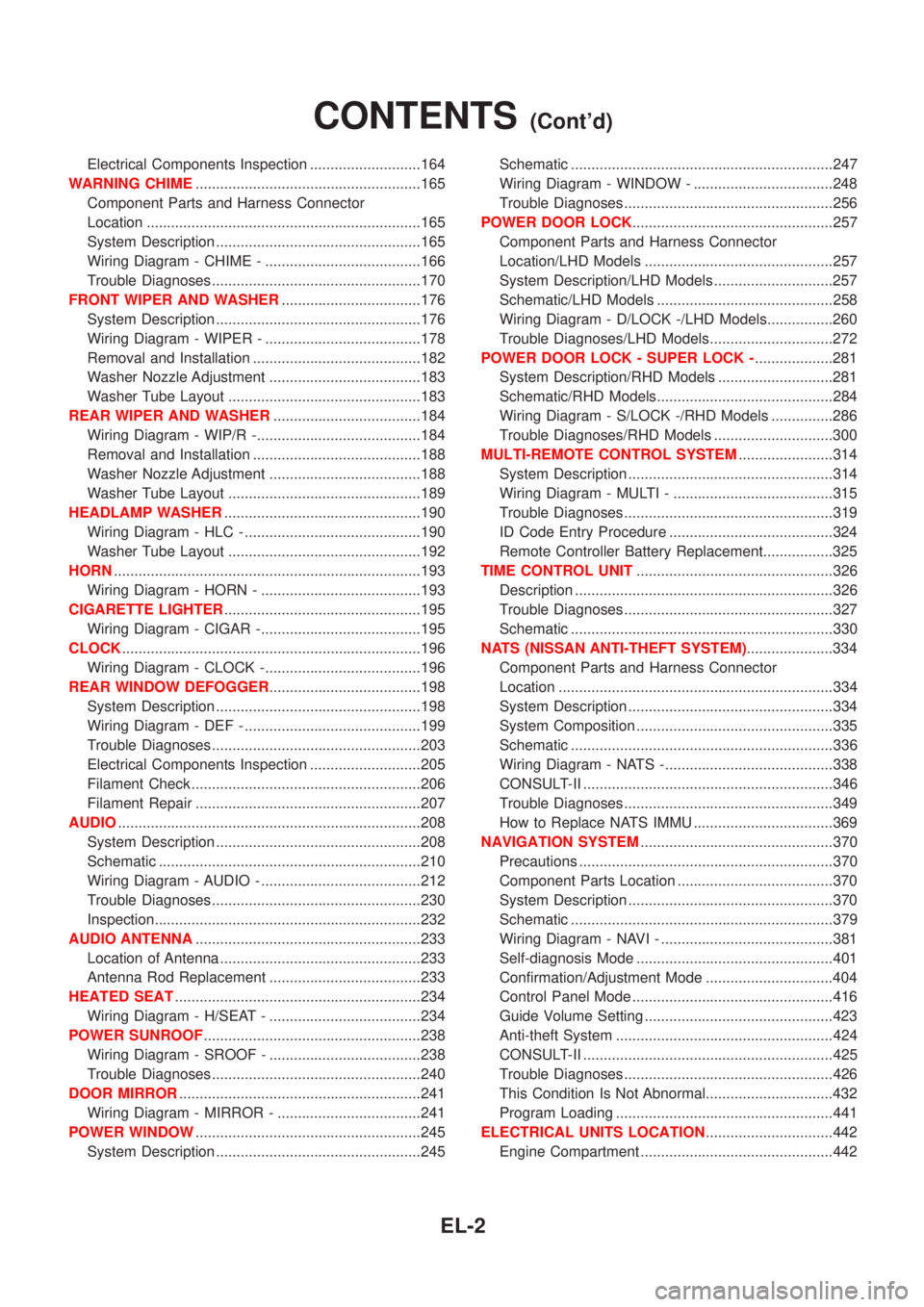
Electrical Components Inspection ...........................164
WARNING CHIME.......................................................165
Component Parts and Harness Connector
Location ...................................................................165
System Description ..................................................165
Wiring Diagram - CHIME - ......................................166
Trouble Diagnoses...................................................170
FRONT WIPER AND WASHER..................................176
System Description ..................................................176
Wiring Diagram - WIPER - ......................................178
Removal and Installation .........................................182
Washer Nozzle Adjustment .....................................183
Washer Tube Layout ...............................................183
REAR WIPER AND WASHER....................................184
Wiring Diagram - WIP/R -........................................184
Removal and Installation .........................................188
Washer Nozzle Adjustment .....................................188
Washer Tube Layout ...............................................189
HEADLAMP WASHER................................................190
Wiring Diagram - HLC - ...........................................190
Washer Tube Layout ...............................................192
HORN...........................................................................193
Wiring Diagram - HORN - .......................................193
CIGARETTE LIGHTER................................................195
Wiring Diagram - CIGAR -.......................................195
CLOCK.........................................................................196
Wiring Diagram - CLOCK -......................................196
REAR WINDOW DEFOGGER.....................................198
System Description ..................................................198
Wiring Diagram - DEF - ...........................................199
Trouble Diagnoses...................................................203
Electrical Components Inspection ...........................205
Filament Check ........................................................206
Filament Repair .......................................................207
AUDIO..........................................................................208
System Description ..................................................208
Schematic ................................................................210
Wiring Diagram - AUDIO - .......................................212
Trouble Diagnoses...................................................230
Inspection.................................................................232
AUDIO ANTENNA.......................................................233
Location of Antenna .................................................233
Antenna Rod Replacement .....................................233
HEATED SEAT............................................................234
Wiring Diagram - H/SEAT - .....................................234
POWER SUNROOF.....................................................238
Wiring Diagram - SROOF - .....................................238
Trouble Diagnoses...................................................240
DOOR MIRROR...........................................................241
Wiring Diagram - MIRROR - ...................................241
POWER WINDOW.......................................................245
System Description ..................................................245Schematic ................................................................247
Wiring Diagram - WINDOW - ..................................248
Trouble Diagnoses...................................................256
POWER DOOR LOCK.................................................257
Component Parts and Harness Connector
Location/LHD Models ..............................................257
System Description/LHD Models .............................257
Schematic/LHD Models ...........................................258
Wiring Diagram - D/LOCK -/LHD Models................260
Trouble Diagnoses/LHD Models..............................272
POWER DOOR LOCK - SUPER LOCK -...................281
System Description/RHD Models ............................281
Schematic/RHD Models...........................................284
Wiring Diagram - S/LOCK -/RHD Models ...............286
Trouble Diagnoses/RHD Models .............................300
MULTI-REMOTE CONTROL SYSTEM.......................314
System Description ..................................................314
Wiring Diagram - MULTI - .......................................315
Trouble Diagnoses...................................................319
ID Code Entry Procedure ........................................324
Remote Controller Battery Replacement.................325
TIME CONTROL UNIT................................................326
Description ...............................................................326
Trouble Diagnoses...................................................327
Schematic ................................................................330
NATS (NISSAN ANTI-THEFT SYSTEM).....................334
Component Parts and Harness Connector
Location ...................................................................334
System Description ..................................................334
System Composition ................................................335
Schematic ................................................................336
Wiring Diagram - NATS -.........................................338
CONSULT-II .............................................................346
Trouble Diagnoses...................................................349
How to Replace NATS IMMU ..................................369
NAVIGATION SYSTEM...............................................370
Precautions ..............................................................370
Component Parts Location ......................................370
System Description ..................................................370
Schematic ................................................................379
Wiring Diagram - NAVI - ..........................................381
Self-diagnosis Mode ................................................401
Confirmation/Adjustment Mode ...............................404
Control Panel Mode .................................................416
Guide Volume Setting ..............................................423
Anti-theft System .....................................................424
CONSULT-II .............................................................425
Trouble Diagnoses...................................................426
This Condition Is Not Abnormal...............................432
Program Loading .....................................................441
ELECTRICAL UNITS LOCATION...............................442
Engine Compartment ...............................................442
CONTENTS(Cont'd)
EL-2
Page 1860 of 3051
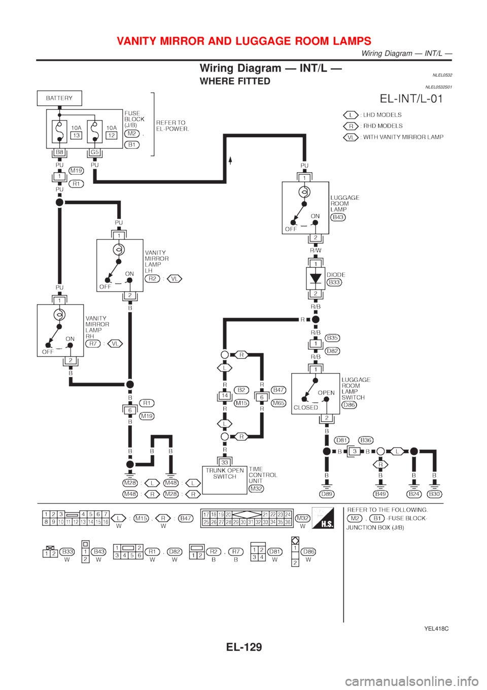
Wiring Diagram Ð INT/L ÐNLEL0532WHERE FITTEDNLEL0532S01
YEL418C
VANITY MIRROR AND LUGGAGE ROOM LAMPS
Wiring Diagram Ð INT/L Ð
EL-129
Page 1929 of 3051
System Description=NLEL0463The rear window defogger system is controlled by the time control unit. The rear window defogger operates
only for approximately 15 minutes.
Power is supplied at all times
+through 15A fuse [No. 7, located in the fuse block (J/B)]
+to rear window defogger relay terminal 5 (B8 relay models) or 3 (B7 relay models)
+through 10A fuse [No. 13, located in the fuse block (J/B)]
+to rear window defogger relay terminal 6 (B6 relay models).
+through 15A fuse [No. 5, located in the fuse block (J/B)]
+to time control unit terminal 9.
With the ignition switch in the ON or START position, power is supplied
+through 10A fuse [No. 10, located in the fuse block (J/B)]
+to the rear window defogger relay terminal 1 and
+to time control unit terminal 1.
Ground is supplied to terminal 5 of the rear window defogger switch through body grounds M28 and M48.
When the rear defogger switch is turned ON, ground is supplied
+through terminal 3 of the rear defogger switch
+to time control unit terminal 3.
Terminal 13 of time control unit then supplies ground to the rear window defogger relay terminal 2.
With power and ground supplied, the rear window defogger relay is energized.
Power is supplied
+through terminals 5 and 7 of the rear window defogger relay (B7 relay models) or
+through terminal 3 of the rear window defogger relay (B8 relay models)
+to the rear window defogger (and door mirror defogger).
The rear window defogger has an independent ground.
With power and ground supplied, the rear window defogger filaments heat and defog the rear window.
When the system is activated, the rear window defogger indicator illuminates in the rear window defogger
switch.
REAR WINDOW DEFOGGER
System Description
EL-198
Page 1972 of 3051
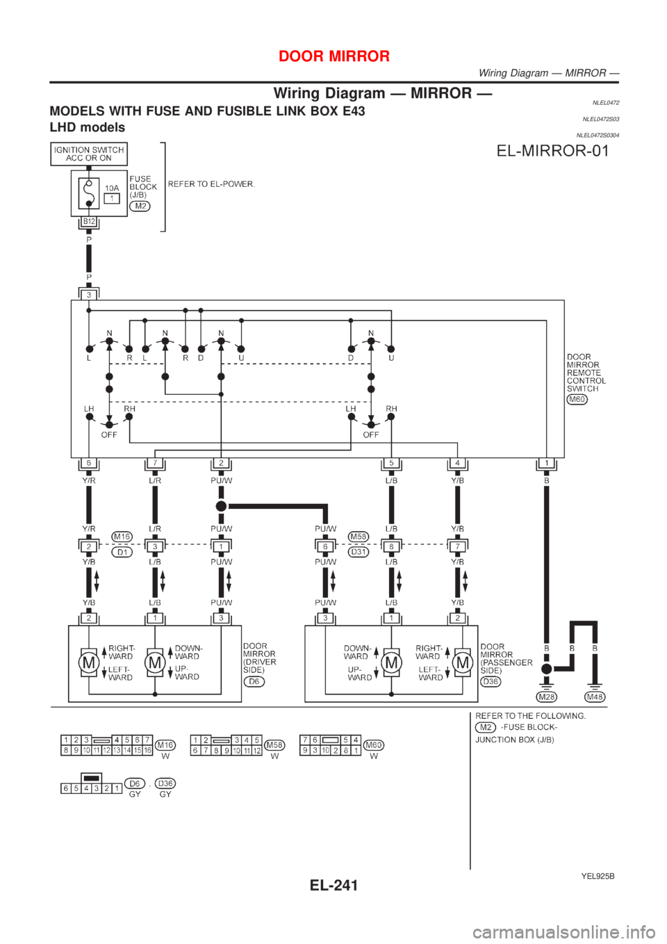
Wiring Diagram Ð MIRROR ÐNLEL0472MODELS WITH FUSE AND FUSIBLE LINK BOX E43NLEL0472S03LHD modelsNLEL0472S0304
YEL925B
DOOR MIRROR
Wiring Diagram Ð MIRROR Ð
EL-241