2001 NISSAN ALMERA TINO jack points
[x] Cancel search: jack pointsPage 2387 of 3051

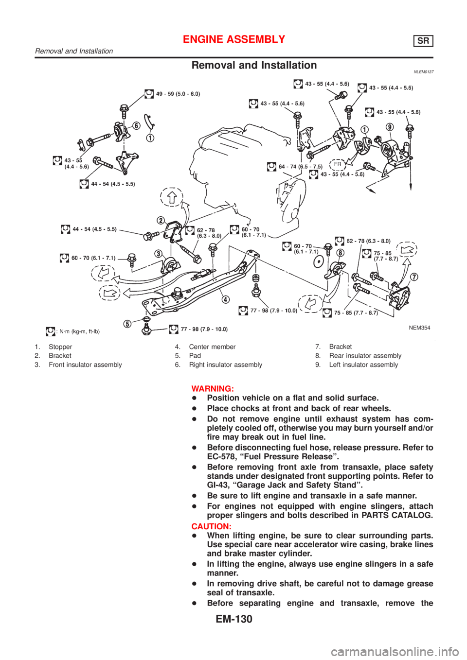
Removal and InstallationNLEM0137
NEM354
1. Stopper
2. Bracket
3. Front insulator assembly4. Center member
5. Pad
6. Right insulator assembly7. Bracket
8. Rear insulator assembly
9. Left insulator assembly
WARNING:
+Position vehicle on a flat and solid surface.
+Place chocks at front and back of rear wheels.
+Do not remove engine until exhaust system has com-
pletely cooled off, otherwise you may burn yourself and/or
fire may break out in fuel line.
+Before disconnecting fuel hose, release pressure. Refer to
EC-578, ªFuel Pressure Releaseº.
+Before removing front axle from transaxle, place safety
stands under designated front supporting points. Refer to
GI-43, ªGarage Jack and Safety Standº.
+Be sure to lift engine and transaxle in a safe manner.
+For engines not equipped with engine slingers, attach
proper slingers and bolts described in PARTS CATALOG.
CAUTION:
+When lifting engine, be sure to clear surrounding parts.
Use special care near accelerator wire casing, brake lines
and brake master cylinder.
+In lifting the engine, always use engine slingers in a safe
manner.
+In removing drive shaft, be careful not to damage grease
seal of transaxle.
+Before separating engine and transaxle, remove the
ENGINE ASSEMBLYSR
Removal and Installation
EM-130
Page 2475 of 3051

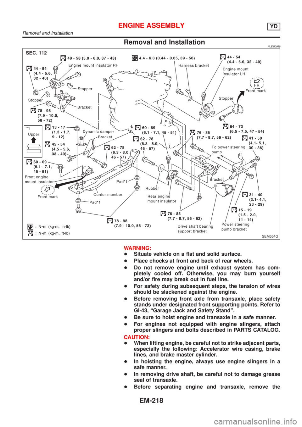
Removal and InstallationNLEM0069
SEM554G
WARNING:
+Situate vehicle on a flat and solid surface.
+Place chocks at front and back of rear wheels.
+Do not remove engine until exhaust system has com-
pletely cooled off. Otherwise, you may burn yourself
and/or fire may break out in fuel line.
+For safety during subsequent steps, the tension of wires
should be slackened against the engine.
+Before removing front axle from transaxle, place safety
stands under designated front supporting points. Refer to
GI-43, ªGarage Jack and Safety Standº.
+Be sure to hoist engine and transaxle in a safe manner.
+For engines not equipped with engine slingers, attach
proper slingers and bolts described in PARTS CATALOG.
CAUTION:
+When lifting engine, be careful not to strike adjacent parts,
especially the following: Accelerator wire casing, brake
lines, and brake master cylinder.
+In hoisting the engine, always use engine slingers in a
safe manner.
+In removing drive shaft, be careful not to damage grease
seal of transaxle.
+Before separating engine and transaxle, remove the
ENGINE ASSEMBLYYD
Removal and Installation
EM-218
Page 2540 of 3051

GENERAL INFORMATION
SECTION
GI
CONTENTS
PRECAUTIONS...............................................................3
Precautions ..................................................................3
PRECAUTIONS FOR SUPPLEMENTAL
RESTRAINT SYSTEM (SRS)″AIR BAG″AND
″SEAT BELT PRE-TENSIONER″
.................................3
PRECAUTIONS FOR NATS (NISSAN ANTI-THEFT
SYSTEM)
..................................................................3
GENERAL PRECAUTIONS.........................................4
PRECAUTIONS FOR MULTIPORT FUEL
INJECTION SYSTEM OR ENGINE CONTROL
SYSTEM
...................................................................6
PRECAUTIONS FOR THREE WAY CATALYST...........6
PRECAUTIONS FOR HOSES.....................................6
PRECAUTIONS FOR ENGINE OILS...........................7
PRECAUTIONS FOR FUEL........................................8
PRECAUTIONS FOR AIR CONDITIONING..................8
HOW TO USE THIS MANUAL........................................9
HOW TO READ WIRING DIAGRAMS.......................... 11
Sample/Wiring Diagram - EXAMPL - ........................ 11
OPTIONAL SPLICE..................................................12
Description .................................................................13
CONNECTOR SYMBOLS.........................................15
HARNESS INDICATION...........................................16
COMPONENT INDICATION......................................16
SWITCH POSITIONS...............................................16
DETECTABLE LINES AND NON-DETECTABLE
LINES
.....................................................................17
MULTIPLE SWITCH.................................................18
REFERENCE AREA.................................................19
HOW TO PERFORM EFFICIENT DIAGNOSES
FOR AN ELECTRICAL INCIDENT...............................21
Work Flow ..................................................................21
Incident Simulation Tests ...........................................22
INTRODUCTION......................................................22
VEHICLE VIBRATION..............................................22
HEAT SENSITIVE....................................................23
FREEZING..............................................................23
WATER INTRUSION................................................24
ELECTRICAL LOAD.................................................24
COLD OR HOT START UP.......................................24
Circuit Inspection .......................................................24
INTRODUCTION......................................................24
TESTING FOR″OPENS″IN THE CIRCUIT................25
TESTING FOR″SHORTS″IN THE CIRCUIT..............26
GROUND INSPECTION...........................................27
VOLTAGE DROP TESTS..........................................27
CONTROL UNIT CIRCUIT TEST...............................29
HOW TO FOLLOW TROUBLE DIAGNOSES...............31
How to Follow Test Groups in Trouble Diagnoses ....32
Key to Symbols Signifying Measurements or
Procedures.................................................................33
CONSULT-II CHECKING SYSTEM...............................35
Function and System Application ..............................35
Nickel Metal Hydride Battery Replacement...............35
Checking Equipment..................................................36
CONSULT-II Data Link Connector (DLC) Circuit ......36
INSPECTION PROCEDURE.....................................36
IDENTIFICATION INFORMATION................................37
Model Variation ..........................................................37
PREFIX AND SUFFIX DESIGNATIONS.....................37
Identification Number .................................................38
VEHICLE IDENTIFICATION NUMBER
ARRANGEMENT
.....................................................38
IDENTIFICATION PLATE..........................................39
ENGINE SERIAL NUMBER.......................................39
H.CVT NUMBER......................................................40
MANUAL TRANSAXLE NUMBER..............................40
Dimensions ................................................................41
Wheels and Tires .......................................................41
LIFTING POINTS AND TOW TRUCK TOWING...........42
Preparation ................................................................42
SPECIAL SERVICE TOOLS......................................42
Board-on Lift ..............................................................42
Garage Jack and Safety Stand .................................43
2-pole Lift ...................................................................44
Tow Truck Towing ......................................................45
TOWING A H.CVT MODEL WITH FOUR WHEELS
ON GROUND
..........................................................45
TOWING A H.CVT MODEL WITH REAR WHEELS
RAISED (WITH FRONT WHEELS ON GROUND)
.......45
TOWING POINT.......................................................46
Page 2543 of 3051

The security indicator is located on the instrument panel. The indi-
cator blinks when the ignition switch is in“OFF”or“ACC”position.
Therefore, NATS warns outsiders that the vehicle is equipped with
the anti-theft system.
+When NATS detects trouble, the security indicator lamp lights
up while ignition switch is in“ON”position.
This lighting up indicates that the anti-theft is not functioning,
so prompt service is required.
+When servicing NATS (trouble diagnoses, system initialization
and additional registration of other NATS ignition key IDs),
CONSULT-II hardware and CONSULT-II NATS software is
necessary.
Regarding the procedures of NATS initialization and NATS
ignition key ID registration, refer to CONSULT-II operation
manual, NATS.
Therefore, CONSULT-II NATS software (program card and
operation manual) must be kept strictly confidential to main-
tain the integrity of the anti-theft function.
+When servicing NATS (trouble diagnoses, system initialization
and additional registration of other NATS ignition key IDs), it
may be necessary to re-register original key identification.
Therefore, be sure to receive all keys from vehicle owner. A
maximum of five key IDs can be registered into NATS.
+When failing to start the engine first time using the key of
NATS, start as follows.
a) Leave the ignition key in“ON”position for approximately 5
seconds.
b) Turn ignition key to“OFF”or“LOCK”position and wait approxi-
mately 5 seconds.
c) Repeat step 1 and 2 again.
d) Restart the engine while keeping the key separate from any
others on key-chain.
SGI285
GENERAL PRECAUTIONSNLGI0001S03+Do not operate the engine for an extended period of time
without proper exhaust ventilation.
Keep the work area well ventilated and free of any inflammable
materials. Special care should be taken when handling any
inflammable or poisonous materials, such as gasoline, refrig-
erant gas, etc. When working in a pit or other enclosed area,
be sure to properly ventilate the area before working with haz-
ardous materials.
Do not smoke while working on the vehicle.
SGI231
+Before jacking up the vehicle, apply wheel chocks or other tire
blocks to the wheels to prevent the vehicle from moving. After
jacking up the vehicle, support the vehicle weight with safety
stands at the points designated for proper lifting before work-
ing on the vehicle.
These operations should be done on a level surface.
+When removing a heavy component such as the engine or
transaxle, be careful not to lose your balance and drop them.
Also, do not allow them to strike adjacent parts, especially the
brake tubes and master cylinder.
PRECAUTIONS
Precautions (Cont’d)
GI-4
Page 2582 of 3051

Garage Jack and Safety Stand=NLGI0009S03WARNING:
+Never get under the vehicle while it is supported only by
the jack. Always use safety stands when you have to get
under the vehicle.
+Place wheel chocks at both front and back of the wheels
on the ground.
SGI110A
LIFTING POINTS AND TOW TRUCK TOWING
Garage Jack and Safety Stand
GI-43
Page 2700 of 3051

Headlamp .................................................. EL-69
Headlining - See Roof trim ........................ BT-35
Heated oxygen sensor (HO2S)
(front) . EC-184, 192, 198, 204, 214, 414, 709,
717, 723, 729, 739, 944
Heated oxygen sensor (HO2S) heater
(front) .......................... EC-221, 421, 746, 951
Heated oxygen sensor (HO2S) heater
(rear) ........................... EC-263, 433, 786, 963
Heated oxygen sensor (rear) . EC-227, 237, 246,
256, 426, 752, 761, 770, 779, 956
Heated seat ............................................. EL-234
Height (Dimensions) ................................... GI-41
Hood ............................................................ BT-7
Horn ......................................................... EL-193
How to erase DTC for OBD system .. EC-69, 71,
594, 596, 1096
I
IACV-AAC valve ............. EC-343, 466, 863, 995
IATS - Wiring diagram .... EC-163, 409, 689, 939
IGN/SG - Wiring diagram ................ EC-501, 903
ILL - Wiring diagram ................................ EL-109
INJECT - Wiring diagram .............. EC-495, 1022
IVC - Wiring diagram ...................... EC-362, 476
Identification plate ...................................... GI-39
Idle air control (IAC) system .......... EC-343, 466,
863, 995
Idle air control valve (IACV) ........... EC-343, 466,
863, 995
Idle speed ........................................ EC-46,1111
Ignition coil .................................... EC-907, 1010
Ignition control system ............................ EC-500
Ignition timing ............................................ EC-46
Ignition wire inspection ........................... EC-814
Illumination ............................................... EL-107
Injection nozzle ..................................... EC-1083
Injector removal and installation ....... EC-44, 578
Input shaft (FF M/T) ..................... MT-34, 63, 68
Instrument panel ........................................ BT-22
Intake air temperature sensor ........ EC-161, 407,
687, 937
Intake valve timing control solenoid
valve ............................................ EC-360, 475
Interior lamp on-off control ....................... EL-117
Interior lamp ............................................. EL-116
Interior ........................................................ BT-28
J
Jacking points ............................................ GI-43
Joint connector (J/C) ............................... EL-531
Junction box (J/B) .................................... EL-527
K
KS - Wiring diagram ............................... EC-292
Keyless entry system - See Multi-re-
mote control system ............................. EL-314
Knock sensor (KS) ................. EC-291, 815, 816
Knuckle spindle ........................................... AX-5
L
LOAD - Wiring diagram ................ EC-536, 1051
Length (Dimensions) .................................. GI-41
License lamp ............................................. EL-87
Lifting points ............................................... GI-44
Line pressure test (A/T) ............................. AT-52
Liquid gasket application .............. EM-5, 76, 158
Location of electrical units ....................... EL-442
Lock, door .................................................. BT-18
Lubricant (R134a) A/C .............................. HA-87
Lubricants ................................................. MA-20
Lubrication circuit (engine) .............. LC-4, 24, 43
M
M/T major overhaul ............................. MT-24, 62
M/T removal and installation ..................... MT-18
MAFS - Wiring diagram ........ EC-156, 682, 1143
MAIN - Wiring diagram ......... EC-146, 671, 1136
MIL & Data link connectors circuit ......... EC-545,
1060
MIL/DL - Wiring diagram .... EC-545, 1060, 1303
MIRROR - Wiring diagram ...................... EL-241
Magnet clutch ............................................ HA-90
Mainshaft (M/T) ............................ MT-39, 63, 73
Malfunction indicator lamp (MIL) .............. EC-73,
598, 1097
Manual air conditioner - Wiring
diagram .................................................. HA-27
Manual transaxle number .......................... GI-40
Mass air flow sensor (MAFS) ................ EC-154,
679, 1143
Master cylinder (clutch) ............................. CL-11
Meter ........................................................ EL-130
Mirror defogger ........................................ EL-198
Mirror, door ................................................ BT-63
Misfire ............................................. EC-285, 808
Mode door control linkage
adjustment ............................................. HA-48
Model variation ........................................... GI-37
Molding - See Exterior ............................... BT-38
Multi-remote control system .................... EL-314
Multiport fuel injection (MFI) system . EC-35, 569
Multiport fuel injection precautions ............... GI-6
ALPHABETICAL INDEX
IDX-5
Page 3031 of 3051

SMA829C
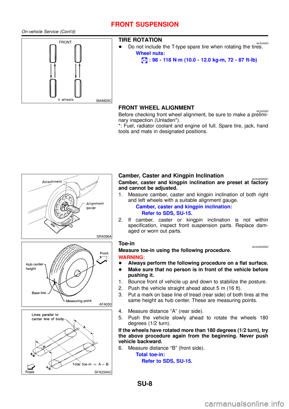
TIRE ROTATIONNLSU0043+Do not include the T-type spare tire when rotating the tires.
Wheel nuts:
:98-118N·m (10.0 - 12.0 kg-m, 72 - 87 ft-lb)
FRONT WHEEL ALIGNMENTNLSU0045Before checking front wheel alignment, be sure to make a prelimi-
nary inspection (Unladen*).
*: Fuel, radiator coolant and engine oil full. Spare tire, jack, hand
tools and mats in designated positions.
SRA096A
Camber, Caster and Kingpin InclinationNLSU0045S01Camber, caster and kingpin inclination are preset at factory
and cannot be adjusted.
1. Measure camber, caster and kingpin inclination of both right
and left wheels with a suitable alignment gauge.
Camber, caster and kingpin inclination:
Refer to SDS, SU-15.
2. If camber, caster or kingpin inclination is not within
specification, inspect front suspension parts. Replace dam-
aged or worn out parts.
AFA050
Toe-inNLSU0045S02Measure toe-in using the following procedure.
WARNING:
+Always perform the following procedure on a flat surface.
+Make sure that no person is in front of the vehicle before
pushing it.
1. Bounce front of vehicle up and down to stabilize the posture.
2. Push the vehicle straight ahead about 5 m (16 ft).
3. Put a mark on base line of tread (rear side) of both tires at the
same height as hub center. These are measuring points.
SFA234AC
4. Measure distance“A”(rear side).
5. Push the vehicle slowly ahead to rotate the wheels 180
degrees (1/2 turn).
If the wheels have rotated more than 180 degrees (1/2 turn), try
the above procedure again from the beginning. Never push
vehicle backward.
6. Measure distance“B”(front side).
Total toe-in:
Refer to SDS, SU-15.
FRONT SUSPENSION
On-vehicle Service (Cont’d)
SU-8