2001 NISSAN ALMERA TINO alternator belt
[x] Cancel search: alternator beltPage 2260 of 3051
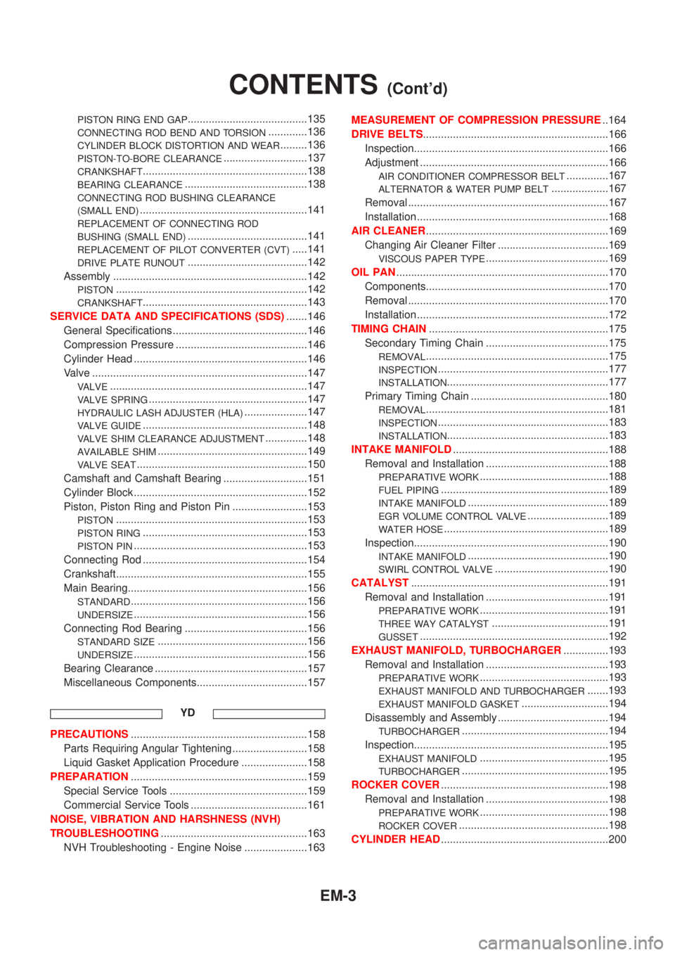
PISTON RING END GAP........................................135
CONNECTING ROD BEND AND TORSION.............136
CYLINDER BLOCK DISTORTION AND WEAR.........136
PISTON-TO-BORE CLEARANCE............................137
CRANKSHAFT.......................................................138
BEARING CLEARANCE.........................................138
CONNECTING ROD BUSHING CLEARANCE
(SMALL END)
........................................................141
REPLACEMENT OF CONNECTING ROD
BUSHING (SMALL END)
........................................141
REPLACEMENT OF PILOT CONVERTER (CVT).....141
DRIVE PLATE RUNOUT........................................142
Assembly .................................................................142
PISTON................................................................142
CRANKSHAFT.......................................................143
SERVICE DATA AND SPECIFICATIONS (SDS).......146
General Specifications .............................................146
Compression Pressure ............................................146
Cylinder Head ..........................................................146
Valve ........................................................................147
VALVE..................................................................147
VALVE SPRING.....................................................147
HYDRAULIC LASH ADJUSTER (HLA).....................147
VALVE GUIDE.......................................................148
VALVE SHIM CLEARANCE ADJUSTMENT..............148
AVAILABLE SHIM..................................................149
VALVE SEAT.........................................................150
Camshaft and Camshaft Bearing ............................151
Cylinder Block ..........................................................152
Piston, Piston Ring and Piston Pin .........................153
PISTON................................................................153
PISTON RING.......................................................153
PISTON PIN..........................................................153
Connecting Rod .......................................................154
Crankshaft................................................................155
Main Bearing............................................................156
STANDARD...........................................................156
UNDERSIZE..........................................................156
Connecting Rod Bearing .........................................156
STANDARD SIZE..................................................156
UNDERSIZE..........................................................156
Bearing Clearance ...................................................157
Miscellaneous Components.....................................157
YD
PRECAUTIONS...........................................................158
Parts Requiring Angular Tightening .........................158
Liquid Gasket Application Procedure ......................158
PREPARATION...........................................................159
Special Service Tools ..............................................159
Commercial Service Tools .......................................161
NOISE, VIBRATION AND HARSHNESS (NVH)
TROUBLESHOOTING.................................................163
NVH Troubleshooting - Engine Noise .....................163MEASUREMENT OF COMPRESSION PRESSURE..164
DRIVE BELTS..............................................................166
Inspection.................................................................166
Adjustment ...............................................................166
AIR CONDITIONER COMPRESSOR BELT..............167
ALTERNATOR & WATER PUMP BELT...................167
Removal ...................................................................167
Installation ................................................................168
AIR CLEANER.............................................................169
Changing Air Cleaner Filter .....................................169
VISCOUS PAPER TYPE.........................................169
OIL PAN.......................................................................170
Components.............................................................170
Removal ...................................................................170
Installation ................................................................172
TIMING CHAIN............................................................175
Secondary Timing Chain .........................................175
REMOVAL.............................................................175
INSPECTION.........................................................177
INSTALLATION......................................................177
Primary Timing Chain ..............................................180
REMOVAL.............................................................181
INSPECTION.........................................................183
INSTALLATION......................................................183
INTAKE MANIFOLD....................................................188
Removal and Installation .........................................188
PREPARATIVE WORK...........................................188
FUEL PIPING........................................................189
INTAKE MANIFOLD...............................................189
EGR VOLUME CONTROL VALVE...........................189
WATER HOSE.......................................................189
Inspection.................................................................190
INTAKE MANIFOLD...............................................190
SWIRL CONTROL VALVE......................................190
CATALYST..................................................................191
Removal and Installation .........................................191
PREPARATIVE WORK...........................................191
THREE WAY CATALYST.......................................191
GUSSET...............................................................192
EXHAUST MANIFOLD, TURBOCHARGER...............193
Removal and Installation .........................................193
PREPARATIVE WORK...........................................193
EXHAUST MANIFOLD AND TURBOCHARGER.......193
EXHAUST MANIFOLD GASKET.............................194
Disassembly and Assembly .....................................194
TURBOCHARGER.................................................194
Inspection.................................................................195
EXHAUST MANIFOLD...........................................195
TURBOCHARGER.................................................195
ROCKER COVER........................................................198
Removal and Installation .........................................198
PREPARATIVE WORK...........................................198
ROCKER COVER..................................................198
CYLINDER HEAD........................................................200
CONTENTS(Cont'd)
EM-3
Page 2274 of 3051
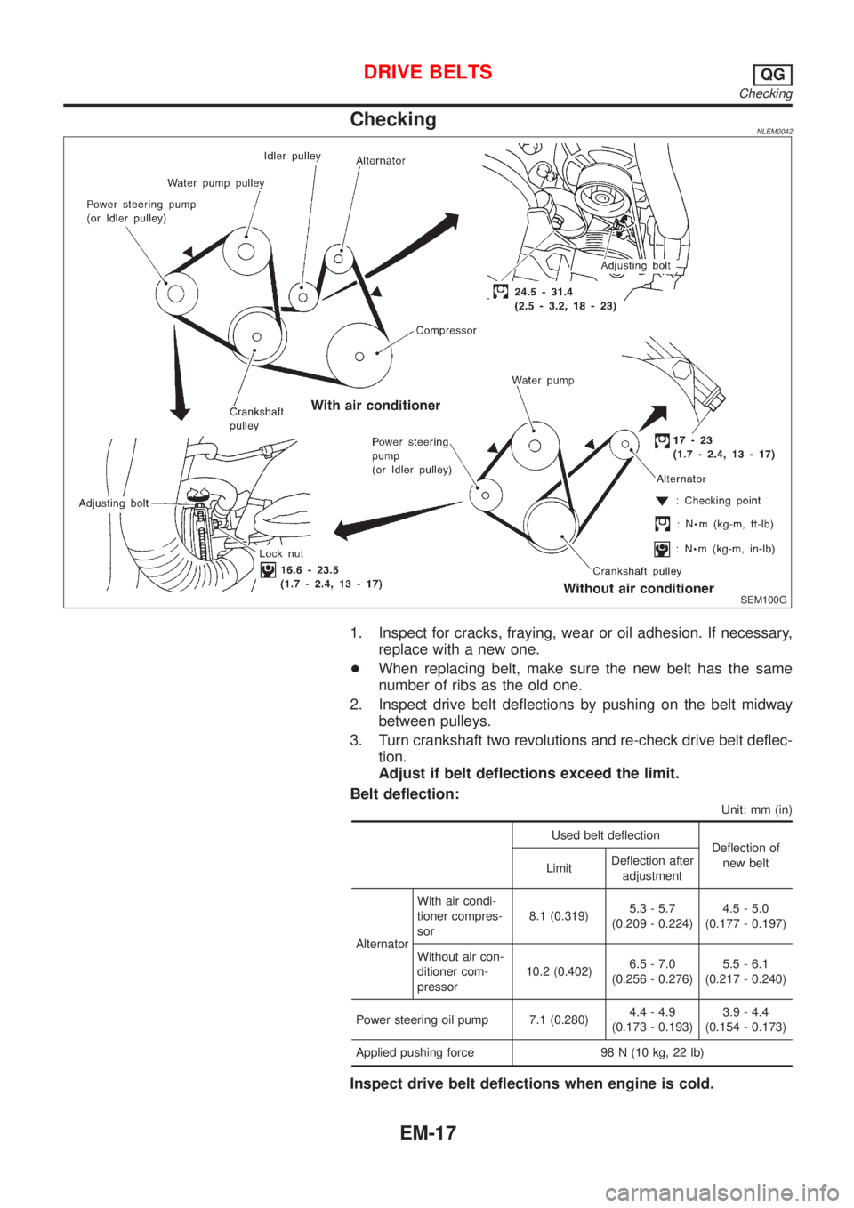
CheckingNLEM0042
SEM100G
1. Inspect for cracks, fraying, wear or oil adhesion. If necessary,
replace with a new one.
+When replacing belt, make sure the new belt has the same
number of ribs as the old one.
2. Inspect drive belt deflections by pushing on the belt midway
between pulleys.
3. Turn crankshaft two revolutions and re-check drive belt deflec-
tion.
Adjust if belt deflections exceed the limit.
Belt deflection:
Unit: mm (in)
Used belt deflection
Deflection of
new belt
LimitDeflection after
adjustment
AlternatorWith air condi-
tioner compres-
sor8.1 (0.319)5.3 - 5.7
(0.209 - 0.224)4.5 - 5.0
(0.177 - 0.197)
Without air con-
ditioner com-
pressor10.2 (0.402)6.5 - 7.0
(0.256 - 0.276)5.5 - 6.1
(0.217 - 0.240)
Power steering oil pump 7.1 (0.280)4.4 - 4.9
(0.173 - 0.193)3.9 - 4.4
(0.154 - 0.173)
Applied pushing force 98 N (10 kg, 22 lb)
Inspect drive belt deflections when engine is cold.
DRIVE BELTSQG
Checking
EM-17
Page 2280 of 3051
CAUTION:
+After removing timing chain, do not turn crankshaft and
camshaft separately, or valves will strike piston heads.
+When installing chain tensioner, oil seals, or other sliding
parts, lubricate contacting surfaces with new engine oil.
+Apply new engine oil to bolt threads and seat surfaces
when installing camshaft sprocket and crankshaft pulley.
+When removing oil pump assembly, remove camshaft
position sensor (PHASE), then remove timing chain from
engine.
+Be careful not to damage sensor edges.
SEM869F
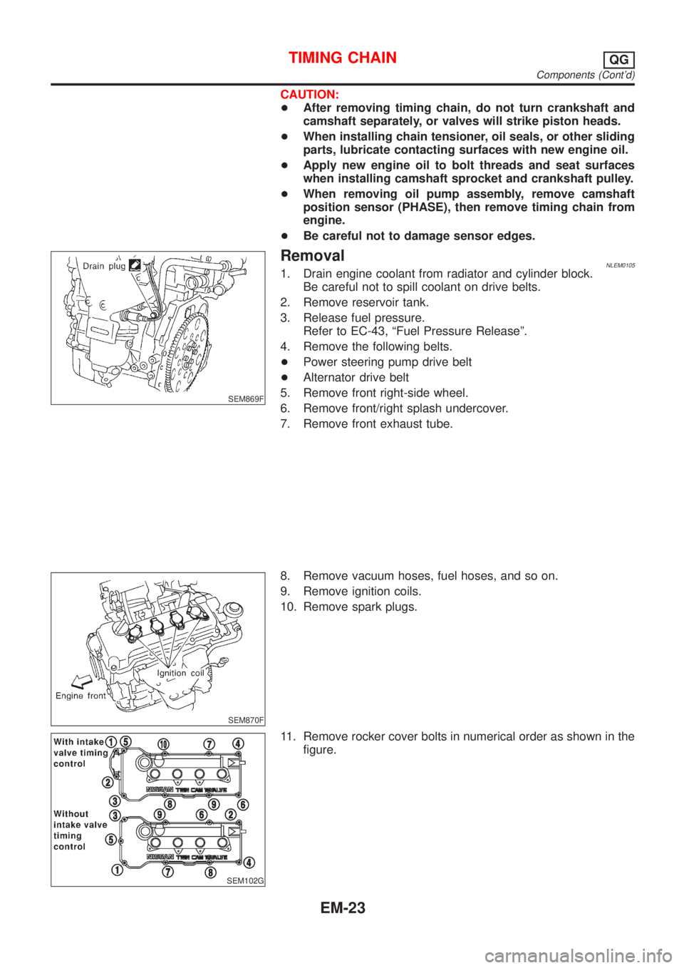
RemovalNLEM01051. Drain engine coolant from radiator and cylinder block.
Be careful not to spill coolant on drive belts.
2. Remove reservoir tank.
3. Release fuel pressure.
Refer to EC-43, ªFuel Pressure Releaseº.
4. Remove the following belts.
+Power steering pump drive belt
+Alternator drive belt
5. Remove front right-side wheel.
6. Remove front/right splash undercover.
7. Remove front exhaust tube.
SEM870F
8. Remove vacuum hoses, fuel hoses, and so on.
9. Remove ignition coils.
10. Remove spark plugs.
SEM102G
11. Remove rocker cover bolts in numerical order as shown in the
figure.
TIMING CHAINQG
Components (Cont'd)
EM-23
Page 2288 of 3051
SEM909F
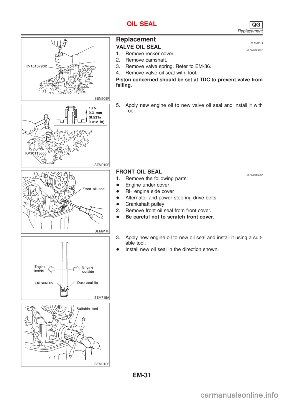
ReplacementNLEM0015VALVE OIL SEALNLEM0015S011. Remove rocker cover.
2. Remove camshaft.
3. Remove valve spring. Refer to EM-36.
4. Remove valve oil seal with Tool.
Piston concerned should be set at TDC to prevent valve from
falling.
SEM910F
5. Apply new engine oil to new valve oil seal and install it with
Tool.
SEM911F
FRONT OIL SEALNLEM0015S021. Remove the following parts:
+Engine under cover
+RH engine side cover
+Alternator and power steering drive belts
+Crankshaft pulley
2. Remove front oil seal from front cover.
+Be careful not to scratch front cover.
SEM715A
SEM912F
3. Apply new engine oil to new oil seal and install it using a suit-
able tool.
+Install new oil seal in the direction shown.
OIL SEALQG
Replacement
EM-31
Page 2307 of 3051
WARNING:
+Position vehicle on a flat and solid surface.
+Place chocks at front and back of rear wheels.
+Do not remove engine until exhaust system has com-
pletely cooled off, otherwise, you may burn yourself
and/or fire may break out in fuel line.
+Before disconnecting fuel hose, release pressure.
Refer to EC-43, ªFuel Pressure Releaseº.
+Be sure to lift engine and transaxle in a safe manner.
+For engines not equipped with engine slingers, attach
proper slingers and bolts described in PARTS CATALOG.
CAUTION:
+When lifting engine, be sure to clear surrounding parts.
Use special care near accelerator wire casing, brake lines
and brake master cylinder.
+When lifting the engine, always use engine slingers in a
safe manner.
+When removing drive shaft, be careful not to damage
grease seal of transaxle.
+Before separating engine and transaxle, remove crank-
shaft position sensor (POS) from the cylinder block
assembly.
+Always be extra careful not to damage edge of crankshaft
position sensor (POS), or signal plate teeth.
Engine cannot be removed separately from transaxle. Remove
engine with transaxle as an assembly.
REMOVALNLEM0022S011. Drain coolant from radiator and cylinder block. Refer to LC-18,
ªChanging Engine Coolantº.
2. Remove coolant reservoir tank and bracket.
3. Drain engine oil.
4. Remove battery and battery tray.
5. Remove air cleaner and air duct.
6. Remove drive belts.
7. Remove alternator and air conditioner compressor from
engine.
8. Remove power steering oil pump from engine and position
aside.
Power steering oil pump does not need to be disconnected
from power steering tubes.
ENGINE ASSEMBLYQG
Removal and Installation (Cont'd)
EM-50
Page 2321 of 3051
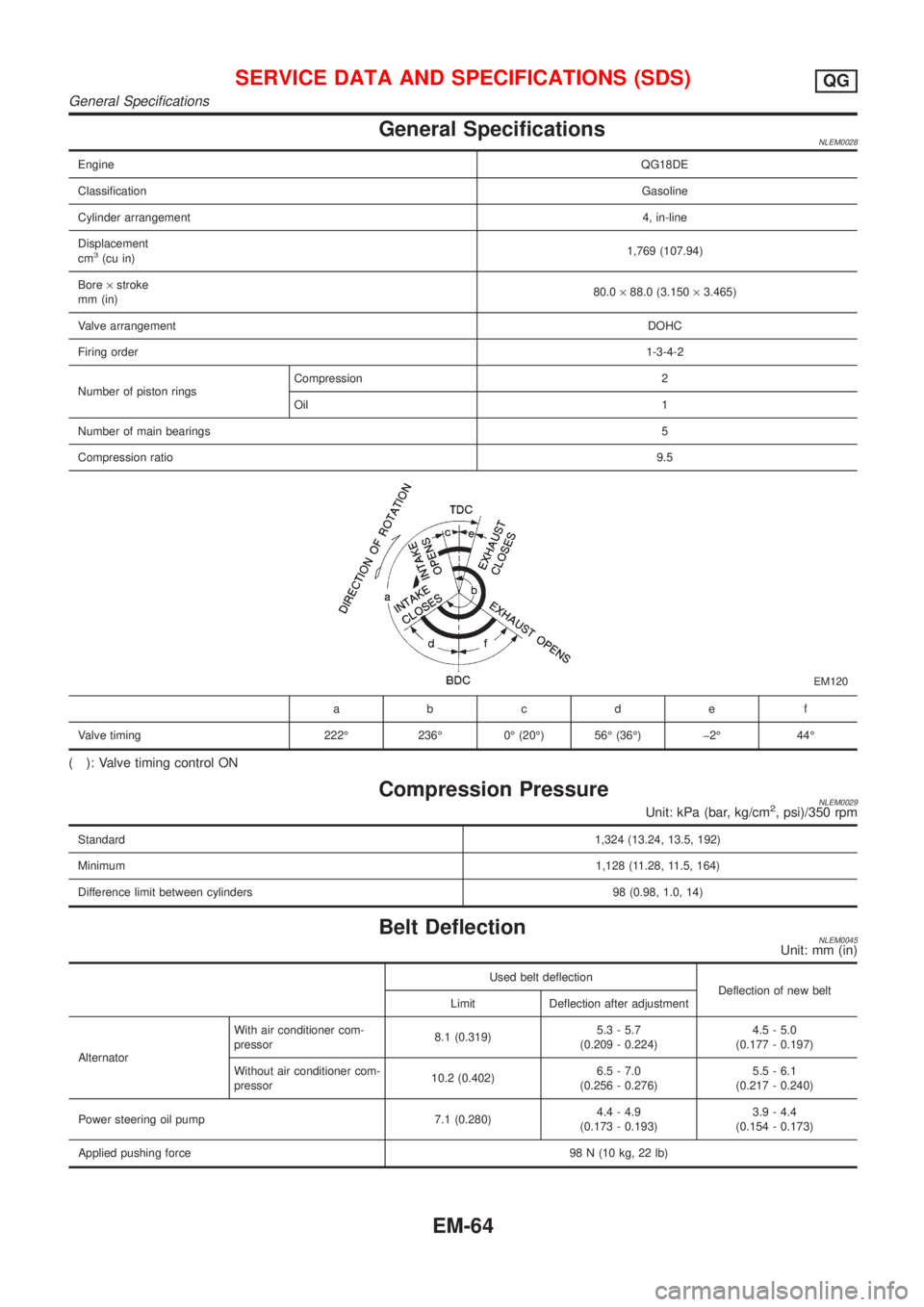
General SpecificationsNLEM0028
EngineQG18DE
ClassificationGasoline
Cylinder arrangement4, in-line
Displacement
cm
3(cu in)1,769 (107.94)
Bore´stroke
mm (in)80.0´88.0 (3.150´3.465)
Valve arrangementDOHC
Firing order1-3-4-2
Number of piston ringsCompression 2
Oil 1
Number of main bearings5
Compression ratio9.5
EM120
abcde f
Valve timing 222É 236É 0É (20É) 56É (36É) þ2É 44É
( ): Valve timing control ON
Compression PressureNLEM0029Unit: kPa (bar, kg/cm2, psi)/350 rpm
Standard1,324 (13.24, 13.5, 192)
Minimum1,128 (11.28, 11.5, 164)
Difference limit between cylinders 98 (0.98, 1.0, 14)
Belt DeflectionNLEM0045Unit: mm (in)
Used belt deflection
Deflection of new belt
Limit Deflection after adjustment
AlternatorWith air conditioner com-
pressor8.1 (0.319)5.3 - 5.7
(0.209 - 0.224)4.5 - 5.0
(0.177 - 0.197)
Without air conditioner com-
pressor10.2 (0.402)6.5 - 7.0
(0.256 - 0.276)5.5 - 6.1
(0.217 - 0.240)
Power steering oil pump 7.1 (0.280)4.4 - 4.9
(0.173 - 0.193)3.9 - 4.4
(0.154 - 0.173)
Applied pushing force98 N (10 kg, 22 lb)
SERVICE DATA AND SPECIFICATIONS (SDS)QG
General Specifications
EM-64
Page 2344 of 3051
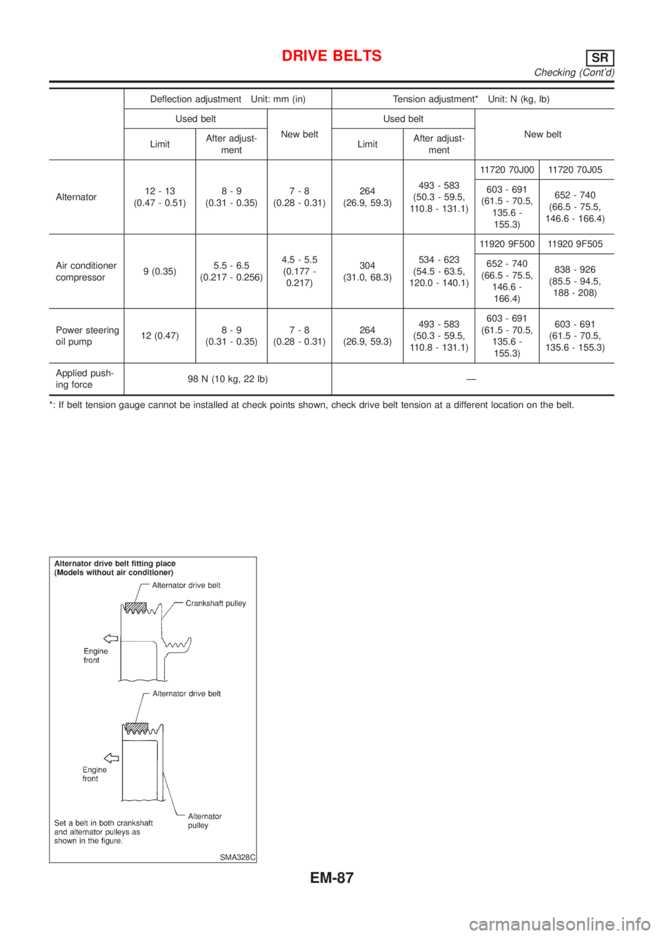
Deflection adjustment Unit: mm (in) Tension adjustment* Unit: N (kg, lb)
Used belt
New beltUsed belt
New belt
LimitAfter adjust-
mentLimitAfter adjust-
ment
Alternator12-13
(0.47 - 0.51)8-9
(0.31 - 0.35)7-8
(0.28 - 0.31)264
(26.9, 59.3)493 - 583
(50.3 - 59.5,
110.8 - 131.1)11720 70J00 11720 70J05
603 - 691
(61.5 - 70.5,
135.6 -
155.3)652 - 740
(66.5 - 75.5,
146.6 - 166.4)
Air conditioner
compressor9 (0.35)5.5 - 6.5
(0.217 - 0.256)4.5 - 5.5
(0.177 -
0.217)304
(31.0, 68.3)534 - 623
(54.5 - 63.5,
120.0 - 140.1)11920 9F500 11920 9F505
652 - 740
(66.5 - 75.5,
146.6 -
166.4)838 - 926
(85.5 - 94.5,
188 - 208)
Power steering
oil pump12 (0.47)8-9
(0.31 - 0.35)7-8
(0.28 - 0.31)264
(26.9, 59.3)493 - 583
(50.3 - 59.5,
110.8 - 131.1)603 - 691
(61.5 - 70.5,
135.6 -
155.3)603 - 691
(61.5 - 70.5,
135.6 - 155.3)
Applied push-
ing force98 N (10 kg, 22 lb) Ð
*: If belt tension gauge cannot be installed at check points shown, check drive belt tension at a different location on the belt.
SMA328C
DRIVE BELTSSR
Checking (Cont'd)
EM-87
Page 2423 of 3051
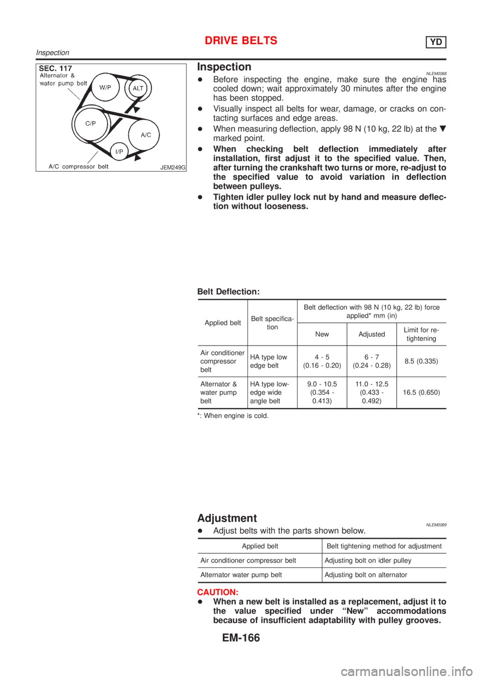
JEM249G
InspectionNLEM0088+Before inspecting the engine, make sure the engine has
cooled down; wait approximately 30 minutes after the engine
has been stopped.
+Visually inspect all belts for wear, damage, or cracks on con-
tacting surfaces and edge areas.
+When measuring deflection, apply 98 N (10 kg, 22 lb) at the.
marked point.
+When checking belt deflection immediately after
installation, first adjust it to the specified value. Then,
after turning the crankshaft two turns or more, re-adjust to
the specified value to avoid variation in deflection
between pulleys.
+Tighten idler pulley lock nut by hand and measure deflec-
tion without looseness.
Belt Deflection:
Applied beltBelt specifica-
tionBelt deflection with 98 N (10 kg, 22 lb) force
applied* mm (in)
New AdjustedLimit for re-
tightening
Air conditioner
compressor
beltHA type low
edge belt4-5
(0.16 - 0.20)6-7
(0.24 - 0.28)8.5 (0.335)
Alternator &
water pump
beltHA type low-
edge wide
angle belt9.0 - 10.5
(0.354 -
0.413)11.0 - 12.5
(0.433 -
0.492)16.5 (0.650)
*: When engine is cold.
AdjustmentNLEM0089+Adjust belts with the parts shown below.
Applied belt Belt tightening method for adjustment
Air conditioner compressor belt Adjusting bolt on idler pulley
Alternator water pump belt Adjusting bolt on alternator
CAUTION:
+When a new belt is installed as a replacement, adjust it to
the value specified under ªNewº accommodations
because of insufficient adaptability with pulley grooves.
DRIVE BELTSYD
Inspection
EM-166