2001 NISSAN ALMERA TINO transmission oil
[x] Cancel search: transmission oilPage 52 of 3051
SAT767B
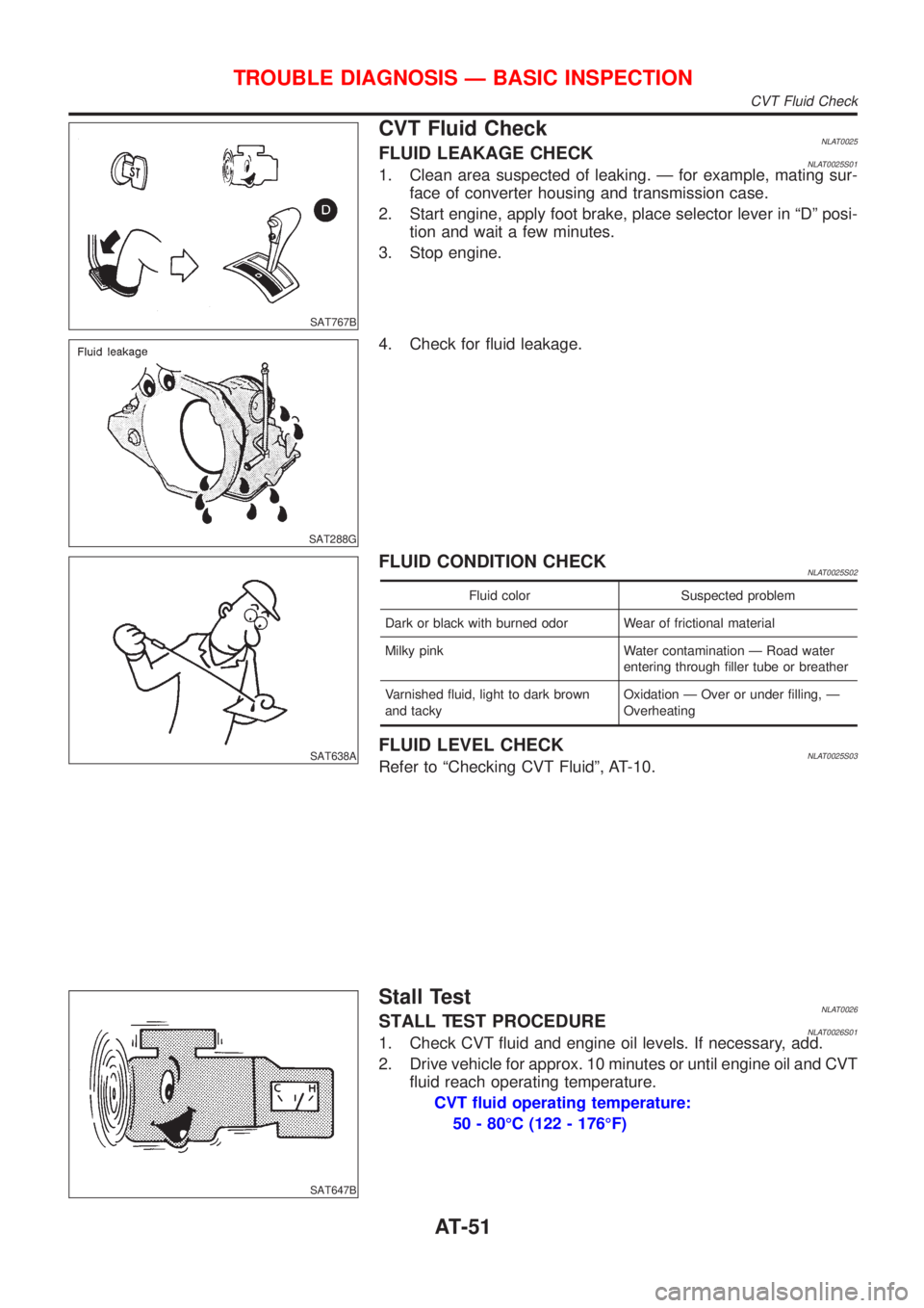
CVT Fluid CheckNLAT0025FLUID LEAKAGE CHECKNLAT0025S011. Clean area suspected of leaking. Ð for example, mating sur-
face of converter housing and transmission case.
2. Start engine, apply foot brake, place selector lever in ªDº posi-
tion and wait a few minutes.
3. Stop engine.
SAT288G
4. Check for fluid leakage.
SAT638A
FLUID CONDITION CHECKNLAT0025S02
Fluid color Suspected problem
Dark or black with burned odor Wear of frictional material
Milky pink Water contamination Ð Road water
entering through filler tube or breather
Varnished fluid, light to dark brown
and tackyOxidation Ð Over or under filling, Ð
Overheating
FLUID LEVEL CHECKNLAT0025S03Refer to ªChecking CVT Fluidº, AT-10.
SAT647B
Stall TestNLAT0026STALL TEST PROCEDURENLAT0026S011. Check CVT fluid and engine oil levels. If necessary, add.
2. Drive vehicle for approx. 10 minutes or until engine oil and CVT
fluid reach operating temperature.
CVT fluid operating temperature:
50 - 80ÉC (122 - 176ÉF)
TROUBLE DIAGNOSIS Ð BASIC INSPECTION
CVT Fluid Check
AT-51
Page 993 of 3051
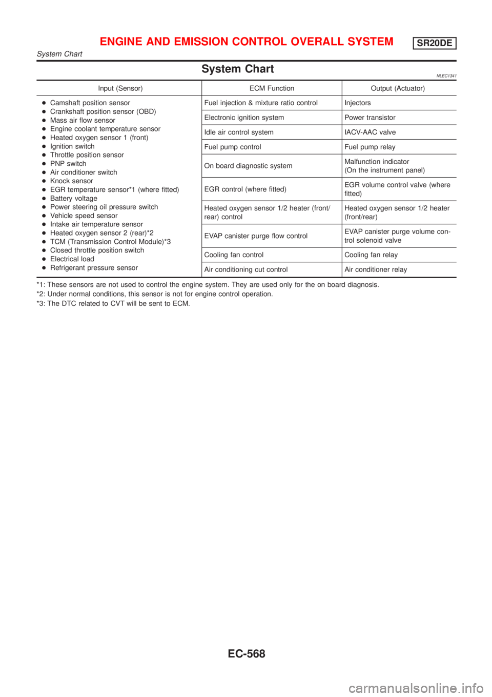
System ChartNLEC1341
Input (Sensor) ECM Function Output (Actuator)
+Camshaft position sensor
+Crankshaft position sensor (OBD)
+Mass air flow sensor
+Engine coolant temperature sensor
+Heated oxygen sensor 1 (front)
+Ignition switch
+Throttle position sensor
+PNP switch
+Air conditioner switch
+Knock sensor
+EGR temperature sensor*1 (where fitted)
+Battery voltage
+Power steering oil pressure switch
+Vehicle speed sensor
+Intake air temperature sensor
+Heated oxygen sensor 2 (rear)*2
+TCM (Transmission Control Module)*3
+Closed throttle position switch
+Electrical load
+Refrigerant pressure sensorFuel injection & mixture ratio control Injectors
Electronic ignition system Power transistor
Idle air control system IACV-AAC valve
Fuel pump control Fuel pump relay
On board diagnostic systemMalfunction indicator
(On the instrument panel)
EGR control (where fitted)EGR volume control valve (where
fitted)
Heated oxygen sensor 1/2 heater (front/
rear) controlHeated oxygen sensor 1/2 heater
(front/rear)
EVAP canister purge flow controlEVAP canister purge volume con-
trol solenoid valve
Cooling fan control Cooling fan relay
Air conditioning cut control Air conditioner relay
*1: These sensors are not used to control the engine system. They are used only for the on board diagnosis.
*2: Under normal conditions, this sensor is not for engine control operation.
*3: The DTC related to CVT will be sent to ECM.
ENGINE AND EMISSION CONTROL OVERALL SYSTEMSR20DE
System Chart
EC-568
Page 1259 of 3051
DescriptionNLEC1545SYSTEM DESCRIPTIONNLEC1545S01
Sensor Input Signal to ECMECM func-
tionActuator
Camshaft position sensor Engine speed
EGR vol-
ume controlEGR volume control valve Mass air flow sensor Amount of intake air
Engine coolant temperature sensor Engine coolant temperature
Ignition switch Start signal
Throttle position sensor Throttle position
Vehicle speed sensor Vehicle speed
Battery Battery voltage
Air conditioner switch Air conditioner operation
Power steering oil pressure switch Power steering load signal
Electrical load Electrical load signal
PNP switch Park/Neutral position signal
TCM (Transmission Control Module) Gear position, shifting signal
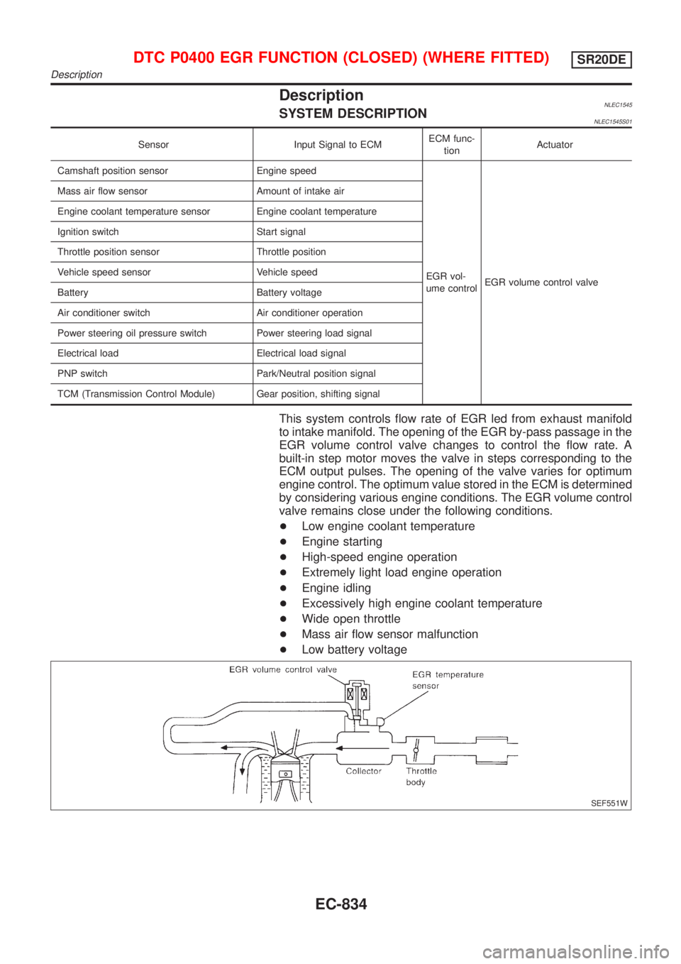
This system controls flow rate of EGR led from exhaust manifold
to intake manifold. The opening of the EGR by-pass passage in the
EGR volume control valve changes to control the flow rate. A
built-in step motor moves the valve in steps corresponding to the
ECM output pulses. The opening of the valve varies for optimum
engine control. The optimum value stored in the ECM is determined
by considering various engine conditions. The EGR volume control
valve remains close under the following conditions.
+Low engine coolant temperature
+Engine starting
+High-speed engine operation
+Extremely light load engine operation
+Engine idling
+Excessively high engine coolant temperature
+Wide open throttle
+Mass air flow sensor malfunction
+Low battery voltage
SEF551W
DTC P0400 EGR FUNCTION (CLOSED) (WHERE FITTED)SR20DE
Description
EC-834
Page 1266 of 3051
DescriptionNLEC1553SYSTEM DESCRIPTIONNLEC1553S01
Sensor Input Signal to ECMECM func-
tionActuator
Crankshaft position sensor Engine speed
EGR vol-
ume controlEGR volume control valve Mass air flow sensor Amount of intake air
Engine coolant temperature sensor Engine coolant temperature
Ignition switch Start signal
Throttle position sensor Throttle position
Vehicle speed sensor Vehicle speed
Battery Battery voltage
Air conditioner switch Air conditioner operation
Power steering oil pressure switch Power steering load signal
Electrical load Electrical load signal
PNP switch Park/Neutral position signal
TCM (Transmission Control Module) Gear position, shifting signal
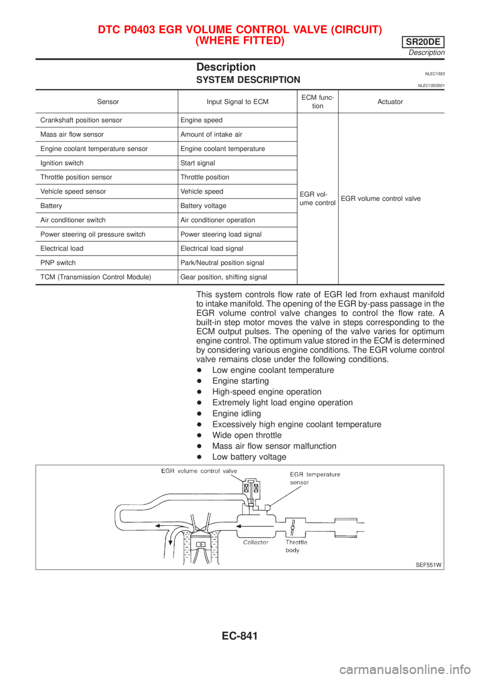
This system controls flow rate of EGR led from exhaust manifold
to intake manifold. The opening of the EGR by-pass passage in the
EGR volume control valve changes to control the flow rate. A
built-in step motor moves the valve in steps corresponding to the
ECM output pulses. The opening of the valve varies for optimum
engine control. The optimum value stored in the ECM is determined
by considering various engine conditions. The EGR volume control
valve remains close under the following conditions.
+Low engine coolant temperature
+Engine starting
+High-speed engine operation
+Extremely light load engine operation
+Engine idling
+Excessively high engine coolant temperature
+Wide open throttle
+Mass air flow sensor malfunction
+Low battery voltage
SEF551W
DTC P0403 EGR VOLUME CONTROL VALVE (CIRCUIT)
(WHERE FITTED)
SR20DE
Description
EC-841
Page 1346 of 3051
DescriptionNLEC1633SYSTEM DESCRIPTIONNLEC1633S01
Sensor Input Signal to ECMECM func-
tionActuator
Camshaft position sensor Engine speed
EGR vol-
ume controlEGR volume control valve Mass air flow sensor Amount of intake air
Engine coolant temperature sensor Engine coolant temperature
Ignition switch Start signal
Throttle position sensor Throttle position
Vehicle speed sensor Vehicle speed
Battery Battery voltage
Air conditioner switch Air conditioner operation
Power steering oil pressure switch Power steering load signal
Electrical load Electrical load signal
Park/Neutral position switch Park/Neutral position
TCM (Transmission Control Module) Gear position, shifting signal
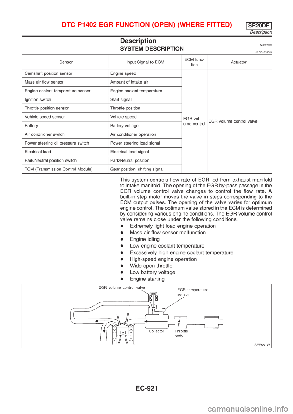
This system controls flow rate of EGR led from exhaust manifold
to intake manifold. The opening of the EGR by-pass passage in the
EGR volume control valve changes to control the flow rate. A
built-in step motor moves the valve in steps corresponding to the
ECM output pulses. The opening of the valve varies for optimum
engine control. The optimum value stored in the ECM is determined
by considering various engine conditions. The EGR volume control
valve remains close under the following conditions.
+Extremely light load engine operation
+Mass air flow sensor malfunction
+Engine idling
+Low engine coolant temperature
+Excessively high engine coolant temperature
+High-speed engine operation
+Wide open throttle
+Low battery voltage
+Engine starting
SEF551W
DTC P1402 EGR FUNCTION (OPEN) (WHERE FITTED)SR20DE
Description
EC-921
Page 1400 of 3051
DescriptionNLEC1818SYSTEM DESCRIPTIONNLEC1818S01
Sensor Input Signal to ECMECM func-
tionActuator
Camshaft position sensor Engine speed
EGR vol-
ume controlEGR volume control valve Mass air flow sensor Amount of intake air
Engine coolant temperature sensor Engine coolant temperature
Ignition switch Start signal
Throttle position sensor Throttle position
Vehicle speed sensor Vehicle speed
Battery Battery voltage
Air conditioner switch Air conditioner operation
Power steering oil pressure switch Power steering load signal
Electrical load Electrical load signal
PNP switch Park/Neutral position signal
TCM (Transmission Control Module) Gear position, shifting signal
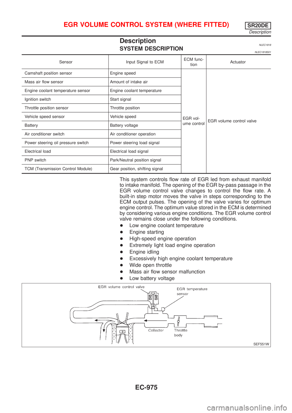
This system controls flow rate of EGR led from exhaust manifold
to intake manifold. The opening of the EGR by-pass passage in the
EGR volume control valve changes to control the flow rate. A
built-in step motor moves the valve in steps corresponding to the
ECM output pulses. The opening of the valve varies for optimum
engine control. The optimum value stored in the ECM is determined
by considering various engine conditions. The EGR volume control
valve remains close under the following conditions.
+Low engine coolant temperature
+Engine starting
+High-speed engine operation
+Extremely light load engine operation
+Engine idling
+Excessively high engine coolant temperature
+Wide open throttle
+Mass air flow sensor malfunction
+Low battery voltage
SEF551W
EGR VOLUME CONTROL SYSTEM (WHERE FITTED)SR20DE
Description
EC-975
Page 2356 of 3051
SEM039G
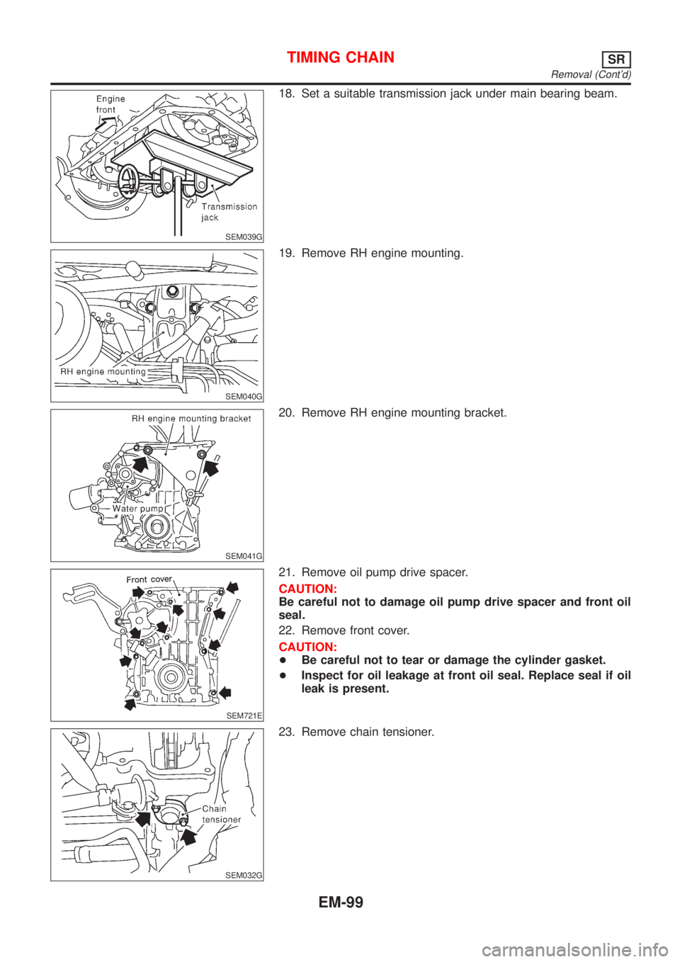
18. Set a suitable transmission jack under main bearing beam.
SEM040G
19. Remove RH engine mounting.
SEM041G
20. Remove RH engine mounting bracket.
SEM721E
21. Remove oil pump drive spacer.
CAUTION:
Be careful not to damage oil pump drive spacer and front oil
seal.
22. Remove front cover.
CAUTION:
+Be careful not to tear or damage the cylinder gasket.
+Inspect for oil leakage at front oil seal. Replace seal if oil
leak is present.
SEM032G
23. Remove chain tensioner.
TIMING CHAINSR
Removal (Cont'd)
EM-99
Page 2388 of 3051
crankshaft position sensor (OBD) from the assembly.
+Always be extra careful not to damage edge of crankshaft
position sensor (OBD) or ring gear teeth.
SEM174D
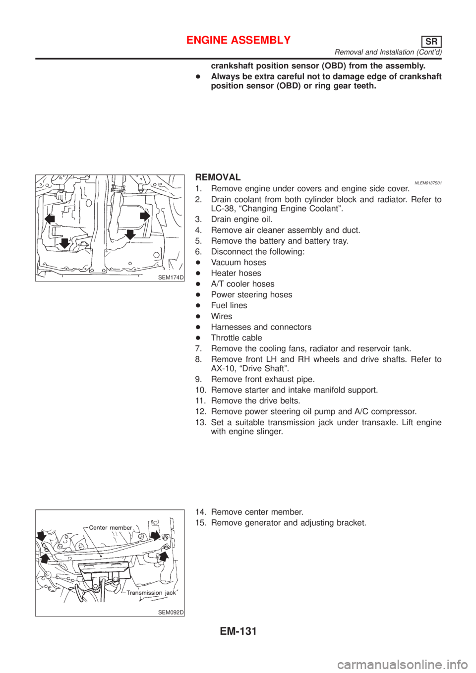
REMOVALNLEM0137S011. Remove engine under covers and engine side cover.
2. Drain coolant from both cylinder block and radiator. Refer to
LC-38, ªChanging Engine Coolantº.
3. Drain engine oil.
4. Remove air cleaner assembly and duct.
5. Remove the battery and battery tray.
6. Disconnect the following:
+Vacuum hoses
+Heater hoses
+A/T cooler hoses
+Power steering hoses
+Fuel lines
+Wires
+Harnesses and connectors
+Throttle cable
7. Remove the cooling fans, radiator and reservoir tank.
8. Remove front LH and RH wheels and drive shafts. Refer to
AX-10, ªDrive Shaftº.
9. Remove front exhaust pipe.
10. Remove starter and intake manifold support.
11. Remove the drive belts.
12. Remove power steering oil pump and A/C compressor.
13. Set a suitable transmission jack under transaxle. Lift engine
with engine slinger.
SEM092D
14. Remove center member.
15. Remove generator and adjusting bracket.
ENGINE ASSEMBLYSR
Removal and Installation (Cont'd)
EM-131