2001 NISSAN ALMERA TINO seat adjustment
[x] Cancel search: seat adjustmentPage 238 of 3051
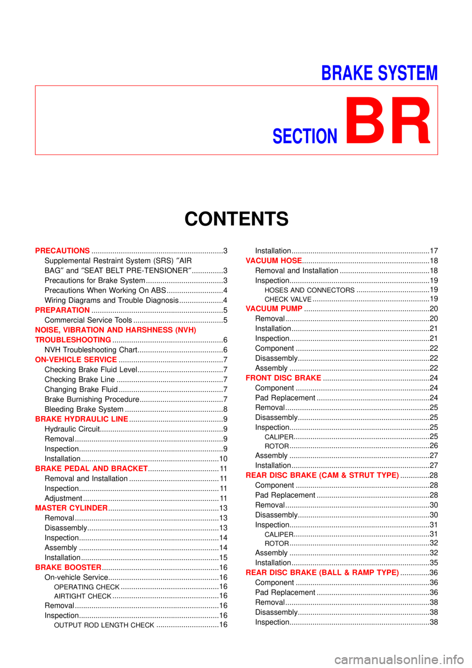
BRAKE SYSTEM
SECTION
BR
CONTENTS
PRECAUTIONS...............................................................3
Supplemental Restraint System (SRS)″AIR
BAG″and″SEAT BELT PRE-TENSIONER″...............3
Precautions for Brake System .....................................3
Precautions When Working On ABS ...........................4
Wiring Diagrams and Trouble Diagnosis .....................4
PREPARATION...............................................................5
Commercial Service Tools ...........................................5
NOISE, VIBRATION AND HARSHNESS (NVH)
TROUBLESHOOTING.....................................................6
NVH Troubleshooting Chart.........................................6
ON-VEHICLE SERVICE..................................................7
Checking Brake Fluid Level.........................................7
Checking Brake Line ...................................................7
Changing Brake Fluid ..................................................7
Brake Burnishing Procedure........................................7
Bleeding Brake System ...............................................8
BRAKE HYDRAULIC LINE.............................................9
Hydraulic Circuit...........................................................9
Removal .......................................................................9
Inspection.....................................................................9
Installation ..................................................................10
BRAKE PEDAL AND BRACKET.................................. 11
Removal and Installation ........................................... 11
Inspection................................................................... 11
Adjustment ................................................................. 11
MASTER CYLINDER.....................................................13
Removal .....................................................................13
Disassembly...............................................................13
Inspection...................................................................14
Assembly ...................................................................14
Installation ..................................................................15
BRAKE BOOSTER........................................................16
On-vehicle Service.....................................................16
OPERATING CHECK...............................................16
AIRTIGHT CHECK...................................................16
Removal .....................................................................16
Inspection...................................................................16
OUTPUT ROD LENGTH CHECK..............................16Installation ..................................................................17
VACUUM HOSE.............................................................18
Removal and Installation ...........................................18
Inspection...................................................................19
HOSES AND CONNECTORS...................................19
CHECK VALVE........................................................19
VACUUM PUMP............................................................20
Removal .....................................................................20
Installation ..................................................................21
Inspection...................................................................21
Component ................................................................22
Disassembly...............................................................22
Assembly ...................................................................22
FRONT DISC BRAKE...................................................24
Component ................................................................24
Pad Replacement ......................................................24
Removal .....................................................................25
Disassembly...............................................................25
Inspection...................................................................25
CALIPER.................................................................25
ROTOR...................................................................26
Assembly ...................................................................27
Installation ..................................................................27
REAR DISC BRAKE (CAM & STRUT TYPE)..............28
Component ................................................................28
Pad Replacement ......................................................28
Removal .....................................................................30
Disassembly...............................................................30
Inspection...................................................................31
CALIPER.................................................................31
ROTOR...................................................................32
Assembly ...................................................................32
Installation ..................................................................35
REAR DISC BRAKE (BALL & RAMP TYPE)..............36
Component ................................................................36
Pad Replacement ......................................................36
Removal .....................................................................38
Disassembly...............................................................38
Inspection...................................................................38
Page 332 of 3051
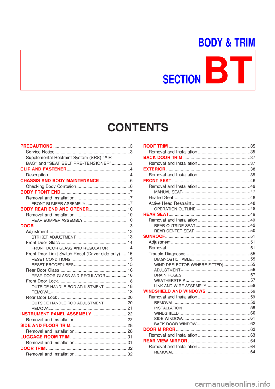
BODY & TRIM
SECTION
BT
CONTENTS
PRECAUTIONS...............................................................3
Service Notice..............................................................3
Supplemental Restraint System (SRS)²AIR
BAG²and²SEAT BELT PRE-TENSIONER²...............3
CLIP AND FASTENER....................................................4
Description ...................................................................4
CHASSIS AND BODY MAINTENANCE.........................6
Checking Body Corrosion ............................................6
BODY FRONT END.........................................................7
Removal and Installation .............................................7
FRONT BUMPER ASSEMBLY....................................7
BODY REAR END AND OPENER................................10
Removal and Installation ...........................................10
REAR BUMPER ASSEMBLY....................................10
DOOR.............................................................................13
Adjustment .................................................................13
STRIKER ADJUSTMENT..........................................13
Front Door Glass .......................................................14
FRONT DOOR GLASS AND REGULATOR................14
Front Door Limit Switch Reset (Driver side only)......15
RESET CONDITIONS..............................................15
RESET PROCEDURES............................................15
Rear Door Glass ........................................................16
REAR DOOR GLASS AND REGULATOR..................16
Front Door Lock .........................................................18
OUTSIDE HANDLE ROD ADJUSTMENT...................18
REMOVAL...............................................................18
Rear Door Lock .........................................................20
OUTSIDE HANDLE ROD ADJUSTMENT...................20
REMOVAL...............................................................21
INSTRUMENT PANEL ASSEMBLY.............................22
Removal and Installation ...........................................22
SIDE AND FLOOR TRIM...............................................28
Removal and Installation ...........................................28
LUGGAGE ROOM TRIM...............................................31
Removal and Installation ...........................................31
DOOR TRIM...................................................................32
Removal and Installation ...........................................32ROOF TRIM...................................................................35
Removal and Installation ...........................................35
BACK DOOR TRIM.......................................................37
Removal and Installation ...........................................37
EXTERIOR.....................................................................38
Removal and Installation ...........................................38
FRONT SEAT................................................................46
Removal and Installation ...........................................46
MANUAL SEAT........................................................47
Heated Seat ...............................................................48
Active Head Restraint ................................................48
OPERATION OUTLINE............................................48
REAR SEAT...................................................................49
Removal and Installation ...........................................49
REAR OUTSIDE SEAT.............................................49
REAR CENTER SEAT..............................................50
SUNROOF......................................................................51
Adjustment .................................................................51
Removal .....................................................................51
Trouble Diagnoses.....................................................55
DIAGNOSTIC TABLE................................................55
WIND DEFLECTOR (WHERE FITTED)......................55
ADJUSTMENT.........................................................56
DRAIN HOSES........................................................57
WEATHERSTRIP.....................................................57
LINK AND WIRE ASSEMBLY....................................58
WINDSHIELD AND WINDOWS....................................59
Removal and Installation ...........................................59
REMOVAL...............................................................59
INSTALLATION........................................................59
WINDSHIELD..........................................................60
SIDE WINDOW........................................................61
BACK DOOR WINDOW............................................62
DOOR MIRROR.............................................................63
Removal and Installation ...........................................63
REAR VIEW MIRROR...................................................64
Removal and Installation ...........................................64
REMOVAL...............................................................64
Page 410 of 3051
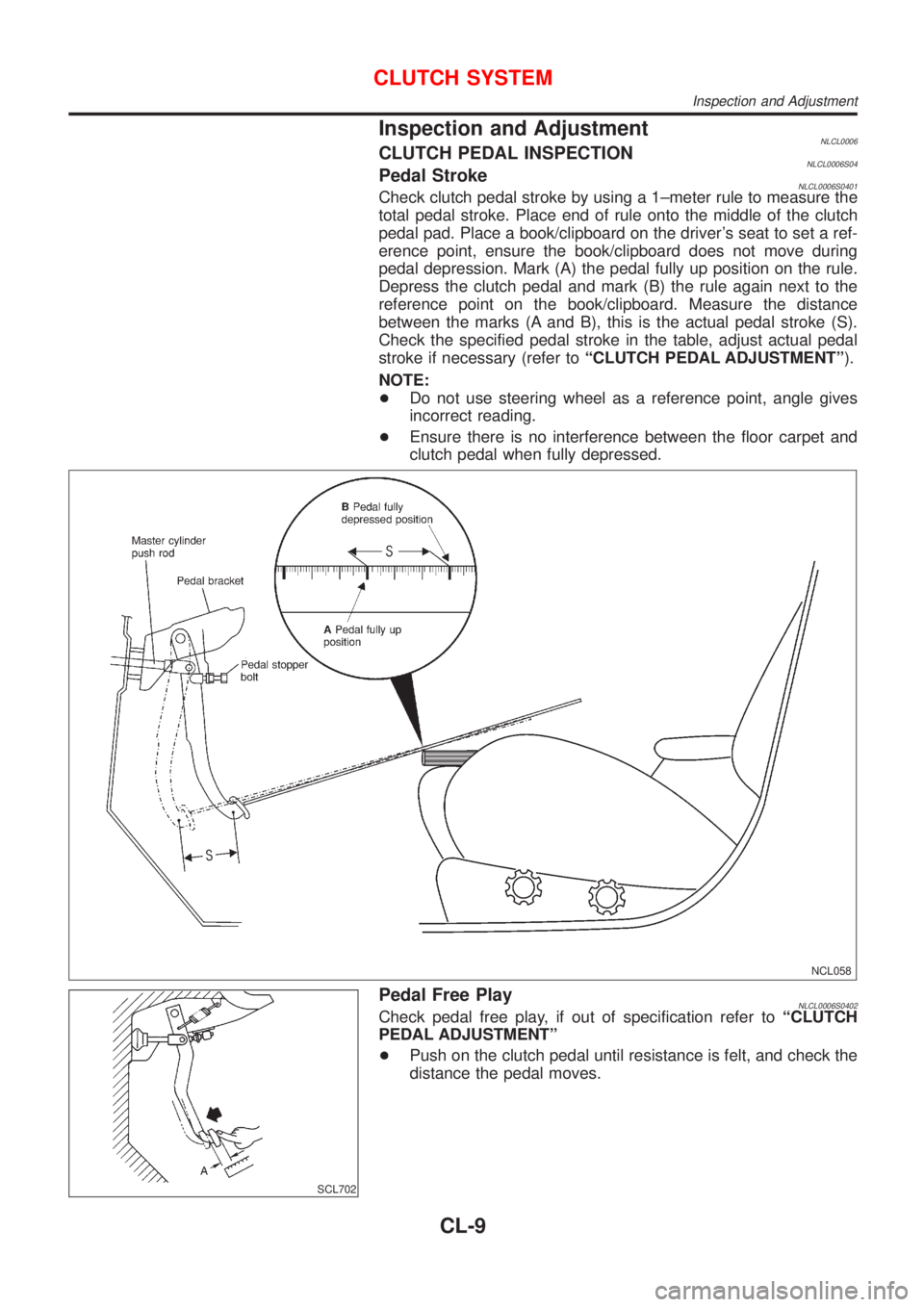
Inspection and AdjustmentNLCL0006CLUTCH PEDAL INSPECTIONNLCL0006S04Pedal StrokeNLCL0006S0401Check clutch pedal stroke by using a 1±meter rule to measure the
total pedal stroke. Place end of rule onto the middle of the clutch
pedal pad. Place a book/clipboard on the driver's seat to set a ref-
erence point, ensure the book/clipboard does not move during
pedal depression. Mark (A) the pedal fully up position on the rule.
Depress the clutch pedal and mark (B) the rule again next to the
reference point on the book/clipboard. Measure the distance
between the marks (A and B), this is the actual pedal stroke (S).
Check the specified pedal stroke in the table, adjust actual pedal
stroke if necessary (refer toªCLUTCH PEDAL ADJUSTMENTº).
NOTE:
+Do not use steering wheel as a reference point, angle gives
incorrect reading.
+Ensure there is no interference between the floor carpet and
clutch pedal when fully depressed.
NCL058
SCL702
Pedal Free PlayNLCL0006S0402Check pedal free play, if out of specification refer toªCLUTCH
PEDAL ADJUSTMENTº
+Push on the clutch pedal until resistance is felt, and check the
distance the pedal moves.
CLUTCH SYSTEM
Inspection and Adjustment
CL-9
Page 1732 of 3051
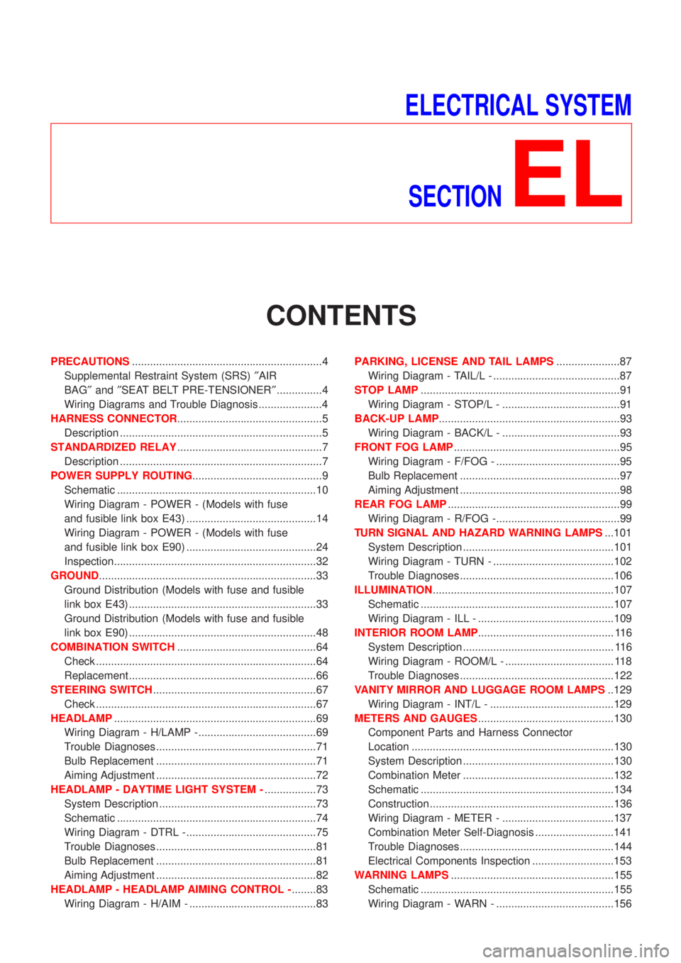
ELECTRICAL SYSTEM
SECTION
EL
CONTENTS
PRECAUTIONS...............................................................4
Supplemental Restraint System (SRS)²AIR
BAG²and²SEAT BELT PRE-TENSIONER²...............4
Wiring Diagrams and Trouble Diagnosis .....................4
HARNESS CONNECTOR................................................5
Description ...................................................................5
STANDARDIZED RELAY................................................7
Description ...................................................................7
POWER SUPPLY ROUTING...........................................9
Schematic ..................................................................10
Wiring Diagram - POWER - (Models with fuse
and fusible link box E43) ...........................................14
Wiring Diagram - POWER - (Models with fuse
and fusible link box E90) ...........................................24
Inspection...................................................................32
GROUND........................................................................33
Ground Distribution (Models with fuse and fusible
link box E43) ..............................................................33
Ground Distribution (Models with fuse and fusible
link box E90) ..............................................................48
COMBINATION SWITCH..............................................64
Check .........................................................................64
Replacement ..............................................................66
STEERING SWITCH......................................................67
Check .........................................................................67
HEADLAMP...................................................................69
Wiring Diagram - H/LAMP -.......................................69
Trouble Diagnoses.....................................................71
Bulb Replacement .....................................................71
Aiming Adjustment .....................................................72
HEADLAMP - DAYTIME LIGHT SYSTEM -.................73
System Description ....................................................73
Schematic ..................................................................74
Wiring Diagram - DTRL - ...........................................75
Trouble Diagnoses.....................................................81
Bulb Replacement .....................................................81
Aiming Adjustment .....................................................82
HEADLAMP - HEADLAMP AIMING CONTROL -........83
Wiring Diagram - H/AIM - ..........................................83PARKING, LICENSE AND TAIL LAMPS.....................87
Wiring Diagram - TAIL/L - ..........................................87
STOP LAMP..................................................................91
Wiring Diagram - STOP/L - .......................................91
BACK-UP LAMP............................................................93
Wiring Diagram - BACK/L - .......................................93
FRONT FOG LAMP.......................................................95
Wiring Diagram - F/FOG - .........................................95
Bulb Replacement .....................................................97
Aiming Adjustment .....................................................98
REAR FOG LAMP.........................................................99
Wiring Diagram - R/FOG -.........................................99
TURN SIGNAL AND HAZARD WARNING LAMPS...101
System Description ..................................................101
Wiring Diagram - TURN - ........................................102
Trouble Diagnoses...................................................106
ILLUMINATION............................................................107
Schematic ................................................................107
Wiring Diagram - ILL - .............................................109
INTERIOR ROOM LAMP............................................. 116
System Description .................................................. 116
Wiring Diagram - ROOM/L - .................................... 118
Trouble Diagnoses...................................................122
VANITY MIRROR AND LUGGAGE ROOM LAMPS..129
Wiring Diagram - INT/L - .........................................129
METERS AND GAUGES.............................................130
Component Parts and Harness Connector
Location ...................................................................130
System Description ..................................................130
Combination Meter ..................................................132
Schematic ................................................................134
Construction .............................................................136
Wiring Diagram - METER - .....................................137
Combination Meter Self-Diagnosis ..........................141
Trouble Diagnoses...................................................144
Electrical Components Inspection ...........................153
WARNING LAMPS......................................................155
Schematic ................................................................155
Wiring Diagram - WARN - .......................................156
Page 1733 of 3051
Electrical Components Inspection ...........................164
WARNING CHIME.......................................................165
Component Parts and Harness Connector
Location ...................................................................165
System Description ..................................................165
Wiring Diagram - CHIME - ......................................166
Trouble Diagnoses...................................................170
FRONT WIPER AND WASHER..................................176
System Description ..................................................176
Wiring Diagram - WIPER - ......................................178
Removal and Installation .........................................182
Washer Nozzle Adjustment .....................................183
Washer Tube Layout ...............................................183
REAR WIPER AND WASHER....................................184
Wiring Diagram - WIP/R -........................................184
Removal and Installation .........................................188
Washer Nozzle Adjustment .....................................188
Washer Tube Layout ...............................................189
HEADLAMP WASHER................................................190
Wiring Diagram - HLC - ...........................................190
Washer Tube Layout ...............................................192
HORN...........................................................................193
Wiring Diagram - HORN - .......................................193
CIGARETTE LIGHTER................................................195
Wiring Diagram - CIGAR -.......................................195
CLOCK.........................................................................196
Wiring Diagram - CLOCK -......................................196
REAR WINDOW DEFOGGER.....................................198
System Description ..................................................198
Wiring Diagram - DEF - ...........................................199
Trouble Diagnoses...................................................203
Electrical Components Inspection ...........................205
Filament Check ........................................................206
Filament Repair .......................................................207
AUDIO..........................................................................208
System Description ..................................................208
Schematic ................................................................210
Wiring Diagram - AUDIO - .......................................212
Trouble Diagnoses...................................................230
Inspection.................................................................232
AUDIO ANTENNA.......................................................233
Location of Antenna .................................................233
Antenna Rod Replacement .....................................233
HEATED SEAT............................................................234
Wiring Diagram - H/SEAT - .....................................234
POWER SUNROOF.....................................................238
Wiring Diagram - SROOF - .....................................238
Trouble Diagnoses...................................................240
DOOR MIRROR...........................................................241
Wiring Diagram - MIRROR - ...................................241
POWER WINDOW.......................................................245
System Description ..................................................245Schematic ................................................................247
Wiring Diagram - WINDOW - ..................................248
Trouble Diagnoses...................................................256
POWER DOOR LOCK.................................................257
Component Parts and Harness Connector
Location/LHD Models ..............................................257
System Description/LHD Models .............................257
Schematic/LHD Models ...........................................258
Wiring Diagram - D/LOCK -/LHD Models................260
Trouble Diagnoses/LHD Models..............................272
POWER DOOR LOCK - SUPER LOCK -...................281
System Description/RHD Models ............................281
Schematic/RHD Models...........................................284
Wiring Diagram - S/LOCK -/RHD Models ...............286
Trouble Diagnoses/RHD Models .............................300
MULTI-REMOTE CONTROL SYSTEM.......................314
System Description ..................................................314
Wiring Diagram - MULTI - .......................................315
Trouble Diagnoses...................................................319
ID Code Entry Procedure ........................................324
Remote Controller Battery Replacement.................325
TIME CONTROL UNIT................................................326
Description ...............................................................326
Trouble Diagnoses...................................................327
Schematic ................................................................330
NATS (NISSAN ANTI-THEFT SYSTEM).....................334
Component Parts and Harness Connector
Location ...................................................................334
System Description ..................................................334
System Composition ................................................335
Schematic ................................................................336
Wiring Diagram - NATS -.........................................338
CONSULT-II .............................................................346
Trouble Diagnoses...................................................349
How to Replace NATS IMMU ..................................369
NAVIGATION SYSTEM...............................................370
Precautions ..............................................................370
Component Parts Location ......................................370
System Description ..................................................370
Schematic ................................................................379
Wiring Diagram - NAVI - ..........................................381
Self-diagnosis Mode ................................................401
Confirmation/Adjustment Mode ...............................404
Control Panel Mode .................................................416
Guide Volume Setting ..............................................423
Anti-theft System .....................................................424
CONSULT-II .............................................................425
Trouble Diagnoses...................................................426
This Condition Is Not Abnormal...............................432
Program Loading .....................................................441
ELECTRICAL UNITS LOCATION...............................442
Engine Compartment ...............................................442
CONTENTS(Cont'd)
EL-2
Page 1829 of 3051
NEL714
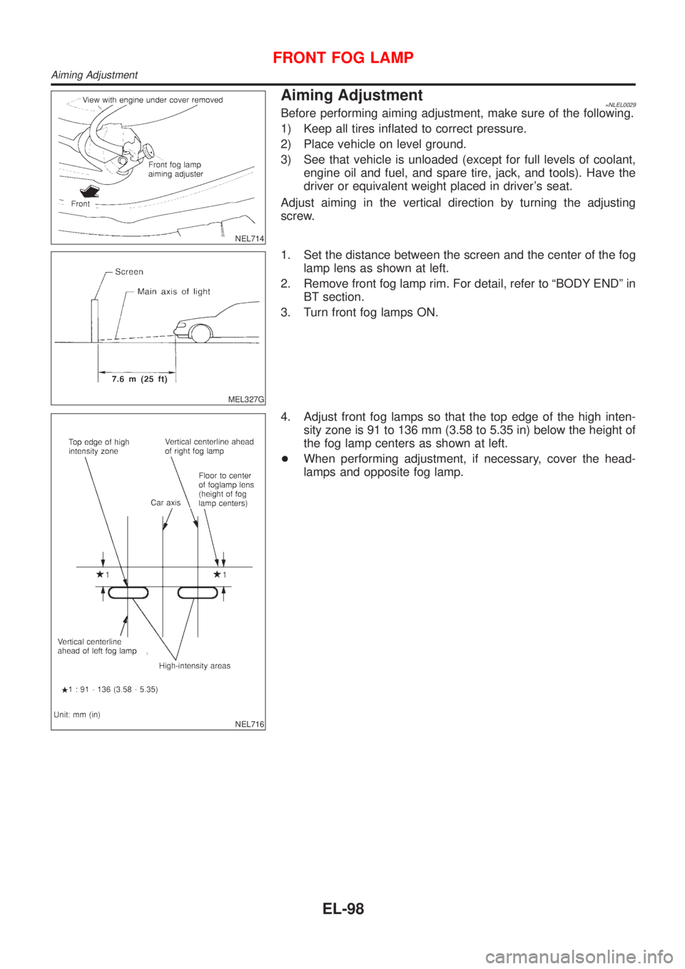
Aiming Adjustment=NLEL0029Before performing aiming adjustment, make sure of the following.
1) Keep all tires inflated to correct pressure.
2) Place vehicle on level ground.
3) See that vehicle is unloaded (except for full levels of coolant,
engine oil and fuel, and spare tire, jack, and tools). Have the
driver or equivalent weight placed in driver's seat.
Adjust aiming in the vertical direction by turning the adjusting
screw.
MEL327G
1. Set the distance between the screen and the center of the fog
lamp lens as shown at left.
2. Remove front fog lamp rim. For detail, refer to ªBODY ENDº in
BT section.
3. Turn front fog lamps ON.
NEL716
4. Adjust front fog lamps so that the top edge of the high inten-
sity zone is 91 to 136 mm (3.58 to 5.35 in) below the height of
the fog lamp centers as shown at left.
+When performing adjustment, if necessary, cover the head-
lamps and opposite fog lamp.
FRONT FOG LAMP
Aiming Adjustment
EL-98
Page 2260 of 3051
PISTON RING END GAP........................................135
CONNECTING ROD BEND AND TORSION.............136
CYLINDER BLOCK DISTORTION AND WEAR.........136
PISTON-TO-BORE CLEARANCE............................137
CRANKSHAFT.......................................................138
BEARING CLEARANCE.........................................138
CONNECTING ROD BUSHING CLEARANCE
(SMALL END)
........................................................141
REPLACEMENT OF CONNECTING ROD
BUSHING (SMALL END)
........................................141
REPLACEMENT OF PILOT CONVERTER (CVT).....141
DRIVE PLATE RUNOUT........................................142
Assembly .................................................................142
PISTON................................................................142
CRANKSHAFT.......................................................143
SERVICE DATA AND SPECIFICATIONS (SDS).......146
General Specifications .............................................146
Compression Pressure ............................................146
Cylinder Head ..........................................................146
Valve ........................................................................147
VALVE..................................................................147
VALVE SPRING.....................................................147
HYDRAULIC LASH ADJUSTER (HLA).....................147
VALVE GUIDE.......................................................148
VALVE SHIM CLEARANCE ADJUSTMENT..............148
AVAILABLE SHIM..................................................149
VALVE SEAT.........................................................150
Camshaft and Camshaft Bearing ............................151
Cylinder Block ..........................................................152
Piston, Piston Ring and Piston Pin .........................153
PISTON................................................................153
PISTON RING.......................................................153
PISTON PIN..........................................................153
Connecting Rod .......................................................154
Crankshaft................................................................155
Main Bearing............................................................156
STANDARD...........................................................156
UNDERSIZE..........................................................156
Connecting Rod Bearing .........................................156
STANDARD SIZE..................................................156
UNDERSIZE..........................................................156
Bearing Clearance ...................................................157
Miscellaneous Components.....................................157
YD
PRECAUTIONS...........................................................158
Parts Requiring Angular Tightening .........................158
Liquid Gasket Application Procedure ......................158
PREPARATION...........................................................159
Special Service Tools ..............................................159
Commercial Service Tools .......................................161
NOISE, VIBRATION AND HARSHNESS (NVH)
TROUBLESHOOTING.................................................163
NVH Troubleshooting - Engine Noise .....................163MEASUREMENT OF COMPRESSION PRESSURE..164
DRIVE BELTS..............................................................166
Inspection.................................................................166
Adjustment ...............................................................166
AIR CONDITIONER COMPRESSOR BELT..............167
ALTERNATOR & WATER PUMP BELT...................167
Removal ...................................................................167
Installation ................................................................168
AIR CLEANER.............................................................169
Changing Air Cleaner Filter .....................................169
VISCOUS PAPER TYPE.........................................169
OIL PAN.......................................................................170
Components.............................................................170
Removal ...................................................................170
Installation ................................................................172
TIMING CHAIN............................................................175
Secondary Timing Chain .........................................175
REMOVAL.............................................................175
INSPECTION.........................................................177
INSTALLATION......................................................177
Primary Timing Chain ..............................................180
REMOVAL.............................................................181
INSPECTION.........................................................183
INSTALLATION......................................................183
INTAKE MANIFOLD....................................................188
Removal and Installation .........................................188
PREPARATIVE WORK...........................................188
FUEL PIPING........................................................189
INTAKE MANIFOLD...............................................189
EGR VOLUME CONTROL VALVE...........................189
WATER HOSE.......................................................189
Inspection.................................................................190
INTAKE MANIFOLD...............................................190
SWIRL CONTROL VALVE......................................190
CATALYST..................................................................191
Removal and Installation .........................................191
PREPARATIVE WORK...........................................191
THREE WAY CATALYST.......................................191
GUSSET...............................................................192
EXHAUST MANIFOLD, TURBOCHARGER...............193
Removal and Installation .........................................193
PREPARATIVE WORK...........................................193
EXHAUST MANIFOLD AND TURBOCHARGER.......193
EXHAUST MANIFOLD GASKET.............................194
Disassembly and Assembly .....................................194
TURBOCHARGER.................................................194
Inspection.................................................................195
EXHAUST MANIFOLD...........................................195
TURBOCHARGER.................................................195
ROCKER COVER........................................................198
Removal and Installation .........................................198
PREPARATIVE WORK...........................................198
ROCKER COVER..................................................198
CYLINDER HEAD........................................................200
CONTENTS(Cont'd)
EM-3
Page 2700 of 3051
Headlamp .................................................. EL-69
Headlining - See Roof trim ........................ BT-35
Heated oxygen sensor (HO2S)
(front) . EC-184, 192, 198, 204, 214, 414, 709,
717, 723, 729, 739, 944
Heated oxygen sensor (HO2S) heater
(front) .......................... EC-221, 421, 746, 951
Heated oxygen sensor (HO2S) heater
(rear) ........................... EC-263, 433, 786, 963
Heated oxygen sensor (rear) . EC-227, 237, 246,
256, 426, 752, 761, 770, 779, 956
Heated seat ............................................. EL-234
Height (Dimensions) ................................... GI-41
Hood ............................................................ BT-7
Horn ......................................................... EL-193
How to erase DTC for OBD system .. EC-69, 71,
594, 596, 1096
I
IACV-AAC valve ............. EC-343, 466, 863, 995
IATS - Wiring diagram .... EC-163, 409, 689, 939
IGN/SG - Wiring diagram ................ EC-501, 903
ILL - Wiring diagram ................................ EL-109
INJECT - Wiring diagram .............. EC-495, 1022
IVC - Wiring diagram ...................... EC-362, 476
Identification plate ...................................... GI-39
Idle air control (IAC) system .......... EC-343, 466,
863, 995
Idle air control valve (IACV) ........... EC-343, 466,
863, 995
Idle speed ........................................ EC-46,1111
Ignition coil .................................... EC-907, 1010
Ignition control system ............................ EC-500
Ignition timing ............................................ EC-46
Ignition wire inspection ........................... EC-814
Illumination ............................................... EL-107
Injection nozzle ..................................... EC-1083
Injector removal and installation ....... EC-44, 578
Input shaft (FF M/T) ..................... MT-34, 63, 68
Instrument panel ........................................ BT-22
Intake air temperature sensor ........ EC-161, 407,
687, 937
Intake valve timing control solenoid
valve ............................................ EC-360, 475
Interior lamp on-off control ....................... EL-117
Interior lamp ............................................. EL-116
Interior ........................................................ BT-28
J
Jacking points ............................................ GI-43
Joint connector (J/C) ............................... EL-531
Junction box (J/B) .................................... EL-527
K
KS - Wiring diagram ............................... EC-292
Keyless entry system - See Multi-re-
mote control system ............................. EL-314
Knock sensor (KS) ................. EC-291, 815, 816
Knuckle spindle ........................................... AX-5
L
LOAD - Wiring diagram ................ EC-536, 1051
Length (Dimensions) .................................. GI-41
License lamp ............................................. EL-87
Lifting points ............................................... GI-44
Line pressure test (A/T) ............................. AT-52
Liquid gasket application .............. EM-5, 76, 158
Location of electrical units ....................... EL-442
Lock, door .................................................. BT-18
Lubricant (R134a) A/C .............................. HA-87
Lubricants ................................................. MA-20
Lubrication circuit (engine) .............. LC-4, 24, 43
M
M/T major overhaul ............................. MT-24, 62
M/T removal and installation ..................... MT-18
MAFS - Wiring diagram ........ EC-156, 682, 1143
MAIN - Wiring diagram ......... EC-146, 671, 1136
MIL & Data link connectors circuit ......... EC-545,
1060
MIL/DL - Wiring diagram .... EC-545, 1060, 1303
MIRROR - Wiring diagram ...................... EL-241
Magnet clutch ............................................ HA-90
Mainshaft (M/T) ............................ MT-39, 63, 73
Malfunction indicator lamp (MIL) .............. EC-73,
598, 1097
Manual air conditioner - Wiring
diagram .................................................. HA-27
Manual transaxle number .......................... GI-40
Mass air flow sensor (MAFS) ................ EC-154,
679, 1143
Master cylinder (clutch) ............................. CL-11
Meter ........................................................ EL-130
Mirror defogger ........................................ EL-198
Mirror, door ................................................ BT-63
Misfire ............................................. EC-285, 808
Mode door control linkage
adjustment ............................................. HA-48
Model variation ........................................... GI-37
Molding - See Exterior ............................... BT-38
Multi-remote control system .................... EL-314
Multiport fuel injection (MFI) system . EC-35, 569
Multiport fuel injection precautions ............... GI-6
ALPHABETICAL INDEX
IDX-5