2001 NISSAN ALMERA TINO steering wheel
[x] Cancel search: steering wheelPage 7 of 3051

Precautions for Supplemental Restraint System
(SRS) ªAIR BAGº and ªSEAT BELT
PRE-TENSIONERº
NLAT0002The Supplemental Restraint System ªAIR BAGº and ªSEAT BELT PRE-TENSIONERº, used along with a seat
belt, help to reduce the risk or severity of injury to the driver and front passenger in a frontal collision. The
Supplemental Restraint System consists of air bag modules (located in the center of the steering wheel and
on the instrument panel on the passenger side), seat belt pre-tensioners, a diagnosis sensor unit, warning
lamp, wiring harness and spiral cable.
In addition to the supplemental air bag modules for a frontal collision, the supplemental side air bag used along
with the seat belt helps to reduce the risk or severity of injury to the driver and front passenger in a side col-
lision. The supplemental side air bag consists of air bag modules (located in the outer side of front seats),
satellite sensor, diagnosis sensor unit (one of components of supplemental air bags for a frontal collision),
wiring harness, warning lamp (one of components of supplemental air bags for a frontal collision). Information
necessary to service the system safely is included in theRS sectionof this Service Manual.
WARNING:
+To avoid rendering the SRS inoperative, which could increase the risk of personal injury or death
in the event of a collision which would result in air bag inflation, all maintenance must be performed
by an authorized NISSAN dealer.
+Improper maintenance, including incorrect removal and installation of the SRS, can lead to per-
sonal injury caused by unintentional activation of the system.
+Do not use electrical test equipment on any circuit related to the SRS unless instructed to in this
Service Manual. SRS wiring harnesses can be identified with yellow harness connector (and with
yellow harness protector or yellow insulation tape before the harness connectors).
Precautions for On Board Diagnostic (EURO-
OBD) System of CVT and Engine
NLAT0198The ECM has an on board diagnostic system. It will light up the malfunction indicator lamp (MI) to warn the
driver of a malfunction causing emission deterioration.
CAUTION:
+Be sure to turn the ignition switch ªOFFº and disconnect the negative battery terminal before any
repair or inspection work. The open/short circuit of related switches, sensors, solenoid valves, etc.
will cause the MI to light up.
+Be sure to connect and lock the connectors securely after work. A loose (unlocked) connector will
cause the MI to light up due to an open circuit. (Be sure the connector is free from water, grease,
dirt, bent terminals, etc.)
+Be sure to route and secure the harnesses properly after work. Interference of the harness with a
bracket, etc. may cause the MI to light up due to a short circuit.
+Be sure to connect rubber tubes properly after work. A misconnected or disconnected rubber tube
may cause the MI to light up due to a malfunction of the EGR system or fuel injection system, etc.
+Be sure to erase the unnecessary malfunction information (repairs completed) from the TCM and
ECM before returning the vehicle to the customer.
SEF289H
PrecautionsNLAT0003+Before connecting or disconnecting the TCM harness
connector, turn ignition switch OFF and disconnect nega-
tive battery terminal. Failure to do so may damage the
TCM. Because battery voltage is applied to TCM even if
ignition switch is turned off.
PRECAUTIONS
Precautions for Supplemental Restraint System (SRS) ªAIR BAGº and ªSEAT BELT PRE-TENSIONERº
AT-6
Page 214 of 3051

Noise, Vibration and Harshness (NVH)
Troubleshooting
=NLAX0004NVH TROUBLESHOOTING CHARTNLAX0004S01Use the chart below to help you find the cause of the symptom. If necessary, repair or replace these parts.
Reference page—
AX-14
—
AX-5, 23
—
AX-3, 22
—
—
SU-4
SU-4
SU-4
BR-6
ST-5
Possible cause and
SUSPECTED PARTS
Excessive joint angle
Joint sliding resistance
Imbalance
Improper installation, looseness
Parts interference
Wheel bearing damage
DRIVE SHAFT
AXLE
SUSPENSION
TIRES
ROAD WHEEL
BRAKES
STEERING
SymptomDRIVE SHAFTNoise, Vibration× × × ×××× ×
Shake× × × ×××× ×
AXLENoise×× × ×××× ×
Shake×× × ×××× ×
Vibration×× × ×× ×
Shimmy×× ×××× ×
Judder× ×××× ×
Poor quality ride or
handling××× ×××
×: Applicable
SMA525A
On-vehicle Service
FRONT AXLE PARTSNLAX0005Check front axle and front suspension parts for excessive play,
cracks, wear or other damage.
+Shake each front wheel to check for excessive play.
+Make sure that cotter pin is inserted.
+Retighten all axle and suspension nuts and bolts to the speci-
fied torque.
Tightening torque:
Refer to SU-4, “FRONT SUSPENSION”.
SFA805B
FRONT WHEEL BEARINGNLAX0006+Check that wheel bearings operate smoothly.
+Check axial end play.
Axial end play:
0.05 mm (0.0020 in)
If out of specification or wheel bearing does not turn smoothly,
replace wheel bearing assembly.
Refer to “Wheel Hub and Knuckle”, “FRONT AXLE”, AX-5.
FRONT AXLE
Noise, Vibration and Harshness (NVH) Troubleshooting
AX-3
Page 219 of 3051

SFA905A
3. Press out bearing outer race.
INSPECTIONNLAX0012Wheel Hub and KnuckleNLAX0012S01Check wheel hub and knuckle for cracks by using a magnetic
exploration or dyeing test.
Snap RingNLAX0012S02Check snap ring for wear or cracks. Replace if necessary.
SFA921B
ASSEMBLYNLAX0013+When removing baffle plate, replace it with a new one.
+When installing the baffle plate, press new plate so that it is in
contact with knuckle wall. Refer to figure at left.
SAX009
1. Install inner snap ring into groove of knuckle.
2. Press new wheel bearing assembly into knuckle until it con-
tacts steering knuckle.
Maximum load P:
29 kN (3 ton, 3.3 US ton, 3.0 Imp ton)
CAUTION:
+Do not press inner race of wheel bearing assembly.
+Do not apply oil or grease to mating surfaces of wheel
bearing outer race and knuckle.
3. Install outer snap ring into groove of knuckle.
SAX010
4. Press wheel hub into knuckle until it stops when the end of the
wheel bearing is hit.
Maximum load P:
29 kN (3 ton, 3.3 US ton, 3.0 Imp ton)
FRONT AXLE
Wheel Hub and Knuckle (Cont’d)
AX-8
Page 243 of 3051

NLBR0005
NVH Troubleshooting ChartNLBR0005S01Use the table below to help you find the cause of the symptom. If necessary, repair or replace these parts.
Reference page
BR-24, 28
BR-24, 28
BR-24, 28
—
—
BR-26, 32
—
—
—
BR-26, 32
NVH in FA section
NVH in FA section
NVH in FA, RA section
NVH in FA section
NVH in ST section
SUSPECTED PARTS
(Possible cause)
Pads - damaged
Pads - uneven wear
Shims damaged
Rotor imbalance
Rotor damage
Rotor runout
Rotor deformation
Rotor deflection
Rotor rust
Rotor thickness variation
DRIVE SHAFT
AXLE AND SUSPENSION
TIRES
ROAD WHEEL
STEERING
Symptom BRAKENoise X X XXXXXX
Shake XXXXXX
Shimmy, Jud-
derXXXXXXX XXXX
X: Applicable
NOISE, VIBRATION AND HARSHNESS (NVH) TROUBLESHOOTING
NVH Troubleshooting Chart
BR-6
Page 279 of 3051

PurposeNLBR0082The ABS consists of electronic and hydraulic components. It allows to control the braking force so that lock-
ing of the wheels can be avoided.
The ABS:
1) Ensures proper tracking performance through steering wheel operation.
2) Enables obstacles to be avoided through steering wheel operation.
3) Ensures vehicle stability by preventing flat spins.
ABS (Anti-Lock Brake System) OperationNLBR0083+When the vehicle speed is less than 10 km/h (6 MPH) this system does not work.
+The Anti-Lock Brake System (ABS) has self-test capabilities. The system turns on the ABS warning lamp
for 1 second after turning the ignition switch ON. The system performs another test the first time the vehicle
reaches 6 km/h (4 MPH). A mechanical noise may be heard as the ABS performs a self-test. This is a
normal part of the self-test feature. If a malfunction is found during this check, the ABS warning lamp will
come on.
+During ABS operation, a mechanical noise may be heard. This is a normal condition.
ABS Hydraulic CircuitNLBR0084
SBR757E
1. Inlet solenoid valve
2. Outlet solenoid valve
3. Reservoir4. Pump
5. Motor6. Bypass check valve
7. Damper
DESCRIPTIONABS
Purpose
BR-42
Page 410 of 3051

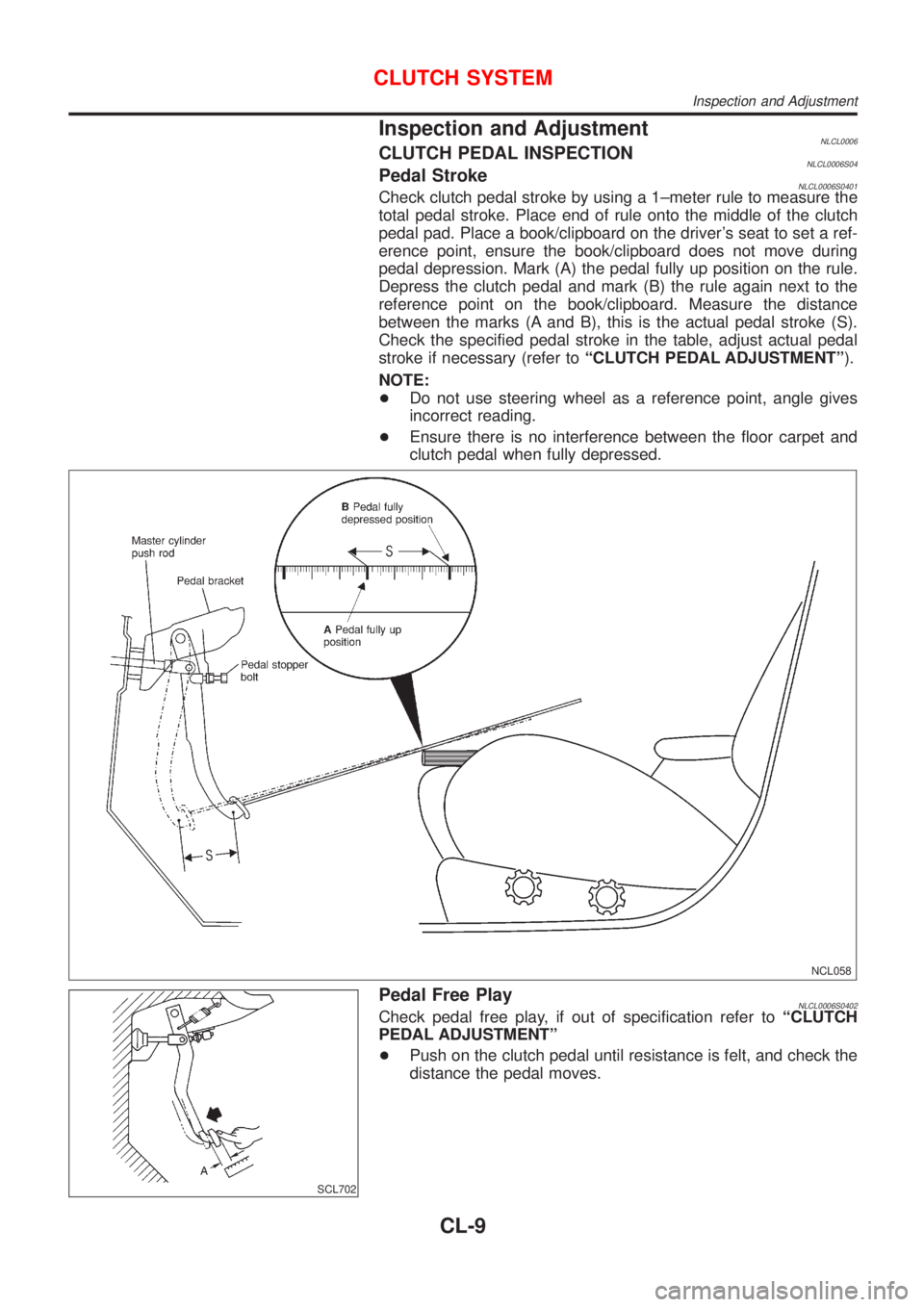
Inspection and AdjustmentNLCL0006CLUTCH PEDAL INSPECTIONNLCL0006S04Pedal StrokeNLCL0006S0401Check clutch pedal stroke by using a 1±meter rule to measure the
total pedal stroke. Place end of rule onto the middle of the clutch
pedal pad. Place a book/clipboard on the driver's seat to set a ref-
erence point, ensure the book/clipboard does not move during
pedal depression. Mark (A) the pedal fully up position on the rule.
Depress the clutch pedal and mark (B) the rule again next to the
reference point on the book/clipboard. Measure the distance
between the marks (A and B), this is the actual pedal stroke (S).
Check the specified pedal stroke in the table, adjust actual pedal
stroke if necessary (refer toªCLUTCH PEDAL ADJUSTMENTº).
NOTE:
+Do not use steering wheel as a reference point, angle gives
incorrect reading.
+Ensure there is no interference between the floor carpet and
clutch pedal when fully depressed.
NCL058
SCL702
Pedal Free PlayNLCL0006S0402Check pedal free play, if out of specification refer toªCLUTCH
PEDAL ADJUSTMENTº
+Push on the clutch pedal until resistance is felt, and check the
distance the pedal moves.
CLUTCH SYSTEM
Inspection and Adjustment
CL-9
Page 446 of 3051

Precautions for Supplemental Restraint System
(SRS) ªAIR BAGº and ªSEAT BELT
PRE-TENSIONERº
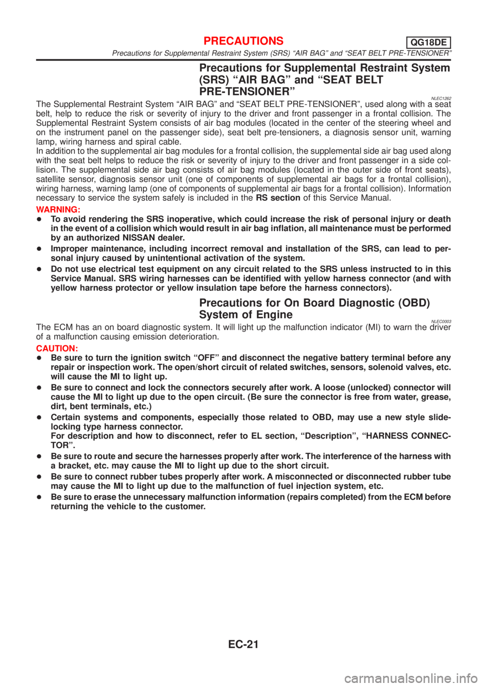
NLEC1262The Supplemental Restraint System ªAIR BAGº and ªSEAT BELT PRE-TENSIONERº, used along with a seat
belt, help to reduce the risk or severity of injury to the driver and front passenger in a frontal collision. The
Supplemental Restraint System consists of air bag modules (located in the center of the steering wheel and
on the instrument panel on the passenger side), seat belt pre-tensioners, a diagnosis sensor unit, warning
lamp, wiring harness and spiral cable.
In addition to the supplemental air bag modules for a frontal collision, the supplemental side air bag used along
with the seat belt helps to reduce the risk or severity of injury to the driver and front passenger in a side col-
lision. The supplemental side air bag consists of air bag modules (located in the outer side of front seats),
satellite sensor, diagnosis sensor unit (one of components of supplemental air bags for a frontal collision),
wiring harness, warning lamp (one of components of supplemental air bags for a frontal collision). Information
necessary to service the system safely is included in theRS sectionof this Service Manual.
WARNING:
+To avoid rendering the SRS inoperative, which could increase the risk of personal injury or death
in the event of a collision which would result in air bag inflation, all maintenance must be performed
by an authorized NISSAN dealer.
+Improper maintenance, including incorrect removal and installation of the SRS, can lead to per-
sonal injury caused by unintentional activation of the system.
+Do not use electrical test equipment on any circuit related to the SRS unless instructed to in this
Service Manual. SRS wiring harnesses can be identified with yellow harness connector (and with
yellow harness protector or yellow insulation tape before the harness connectors).
Precautions for On Board Diagnostic (OBD)
System of Engine
NLEC0003The ECM has an on board diagnostic system. It will light up the malfunction indicator (MI) to warn the driver
of a malfunction causing emission deterioration.
CAUTION:
+Be sure to turn the ignition switch ªOFFº and disconnect the negative battery terminal before any
repair or inspection work. The open/short circuit of related switches, sensors, solenoid valves, etc.
will cause the MI to light up.
+Be sure to connect and lock the connectors securely after work. A loose (unlocked) connector will
cause the MI to light up due to the open circuit. (Be sure the connector is free from water, grease,
dirt, bent terminals, etc.)
+Certain systems and components, especially those related to OBD, may use a new style slide-
locking type harness connector.
For description and how to disconnect, refer to EL section, ªDescriptionº, ªHARNESS CONNEC-
TORº.
+Be sure to route and secure the harnesses properly after work. The interference of the harness with
a bracket, etc. may cause the MI to light up due to the short circuit.
+Be sure to connect rubber tubes properly after work. A misconnected or disconnected rubber tube
may cause the MI to light up due to the malfunction of fuel injection system, etc.
+Be sure to erase the unnecessary malfunction information (repairs completed) from the ECM before
returning the vehicle to the customer.
PRECAUTIONSQG18DE
Precautions for Supplemental Restraint System (SRS) ªAIR BAGº and ªSEAT BELT PRE-TENSIONERº
EC-21
Page 482 of 3051

SEF217Z
SEF454Y
SEF455Y
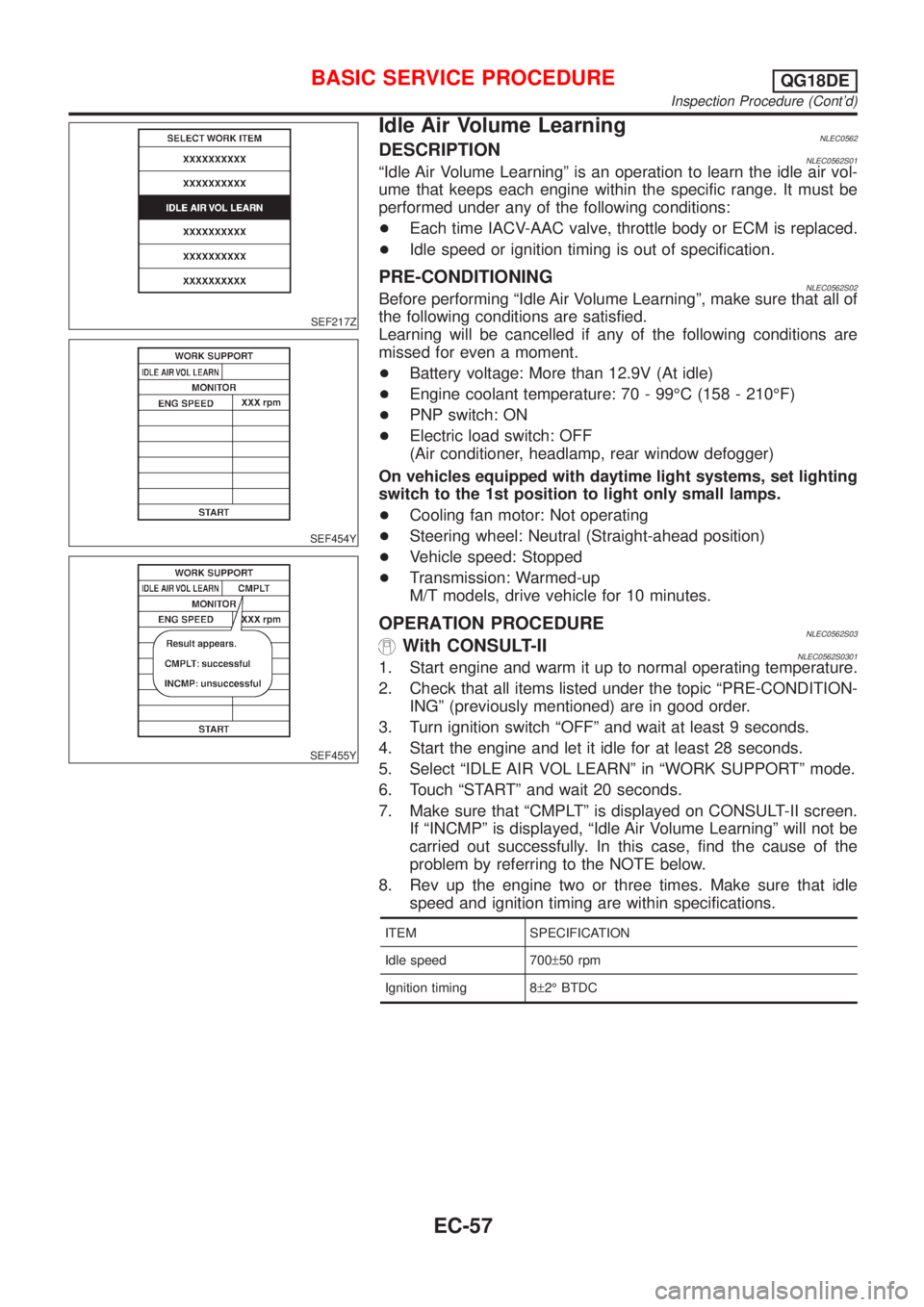
Idle Air Volume LearningNLEC0562DESCRIPTIONNLEC0562S01ªIdle Air Volume Learningº is an operation to learn the idle air vol-
ume that keeps each engine within the specific range. It must be
performed under any of the following conditions:
+Each time IACV-AAC valve, throttle body or ECM is replaced.
+Idle speed or ignition timing is out of specification.
PRE-CONDITIONINGNLEC0562S02Before performing ªIdle Air Volume Learningº, make sure that all of
the following conditions are satisfied.
Learning will be cancelled if any of the following conditions are
missed for even a moment.
+Battery voltage: More than 12.9V (At idle)
+Engine coolant temperature: 70 - 99ÉC (158 - 210ÉF)
+PNP switch: ON
+Electric load switch: OFF
(Air conditioner, headlamp, rear window defogger)
On vehicles equipped with daytime light systems, set lighting
switch to the 1st position to light only small lamps.
+Cooling fan motor: Not operating
+Steering wheel: Neutral (Straight-ahead position)
+Vehicle speed: Stopped
+Transmission: Warmed-up
M/T models, drive vehicle for 10 minutes.
OPERATION PROCEDURENLEC0562S03With CONSULT-IINLEC0562S03011. Start engine and warm it up to normal operating temperature.
2. Check that all items listed under the topic ªPRE-CONDITION-
INGº (previously mentioned) are in good order.
3. Turn ignition switch ªOFFº and wait at least 9 seconds.
4. Start the engine and let it idle for at least 28 seconds.
5. Select ªIDLE AIR VOL LEARNº in ªWORK SUPPORTº mode.
6. Touch ªSTARTº and wait 20 seconds.
7. Make sure that ªCMPLTº is displayed on CONSULT-II screen.
If ªINCMPº is displayed, ªIdle Air Volume Learningº will not be
carried out successfully. In this case, find the cause of the
problem by referring to the NOTE below.
8. Rev up the engine two or three times. Make sure that idle
speed and ignition timing are within specifications.
ITEM SPECIFICATION
Idle speed 700±50 rpm
Ignition timing 8±2É BTDC
BASIC SERVICE PROCEDUREQG18DE
Inspection Procedure (Cont'd)
EC-57