Page 524 of 3051
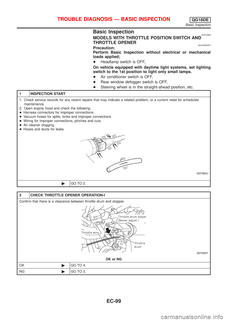
Basic InspectionNLEC0564MODELS WITH THROTTLE POSITION SWITCH AND
THROTTLE OPENER
NLEC0564S01Precaution:
Perform Basic Inspection without electrical or mechanical
loads applied;
+Headlamp switch is OFF,
On vehicle equipped with daytime light systems, set lighting
switch to the 1st position to light only small lamps.
+Air conditioner switch is OFF,
+Rear window defogger switch is OFF,
+Steering wheel is in the straight-ahead position, etc.
1 INSPECTION START
1. Check service records for any recent repairs that may indicate a related problem, or a current need for scheduled
maintenance.
2. Open engine hood and check the following:
+Harness connectors for improper connections
+Vacuum hoses for splits, kinks and improper connections
+Wiring for improper connections, pinches and cuts
+Air cleaner clogging
+Hoses and ducts for leaks
SEF983U
©GO TO 2.
2 CHECK THROTTLE OPENER OPERATION-I
Confirm that there is a clearance between throttle drum and stopper.
SEF850Y
OK or NG
OK©GO TO 4.
NG©GO TO 3.
TROUBLE DIAGNOSIS Ð BASIC INSPECTIONQG18DE
Basic Inspection
EC-99
Page 539 of 3051
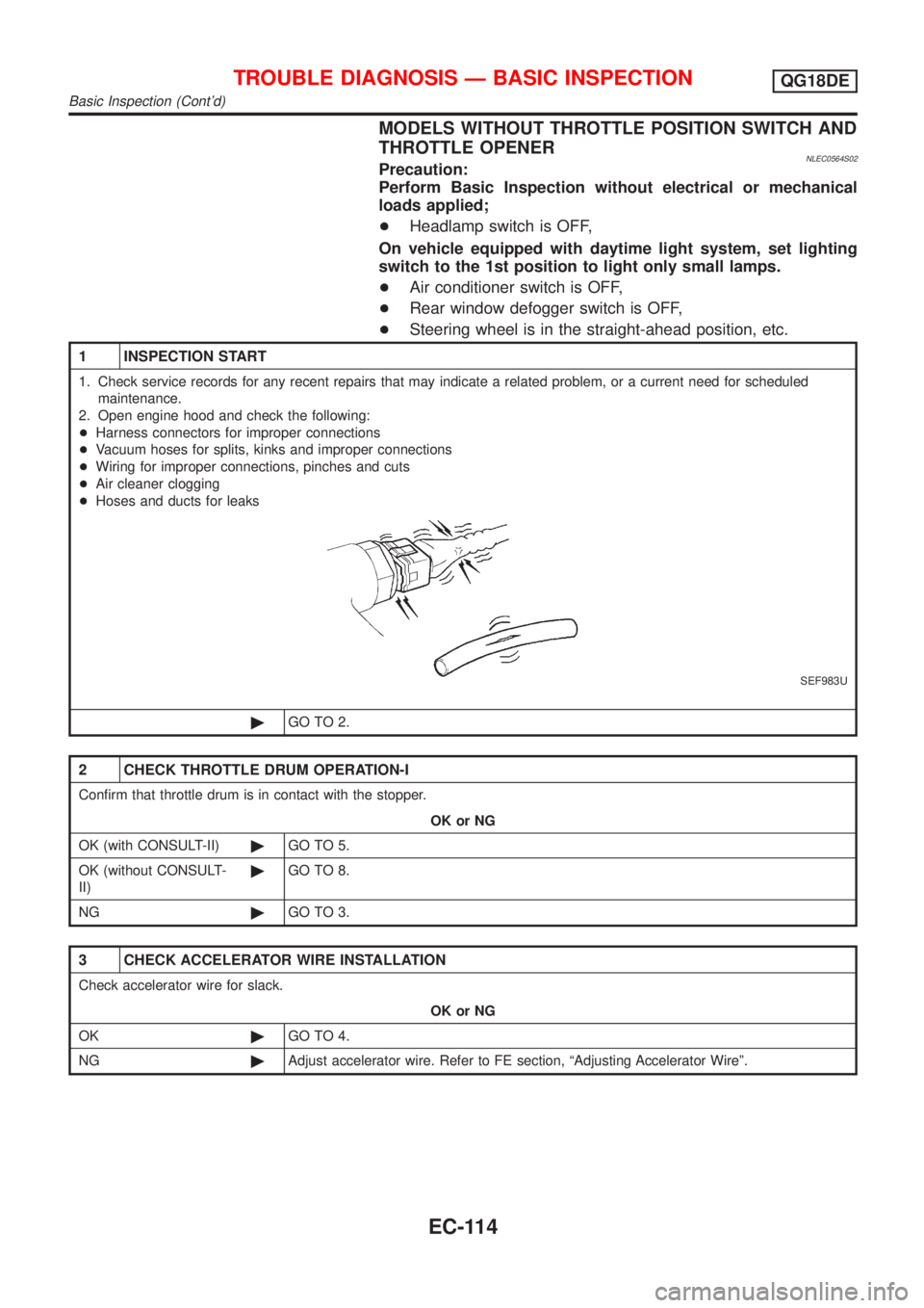
MODELS WITHOUT THROTTLE POSITION SWITCH AND
THROTTLE OPENER
NLEC0564S02Precaution:
Perform Basic Inspection without electrical or mechanical
loads applied;
+Headlamp switch is OFF,
On vehicle equipped with daytime light system, set lighting
switch to the 1st position to light only small lamps.
+Air conditioner switch is OFF,
+Rear window defogger switch is OFF,
+Steering wheel is in the straight-ahead position, etc.
1 INSPECTION START
1. Check service records for any recent repairs that may indicate a related problem, or a current need for scheduled
maintenance.
2. Open engine hood and check the following:
+Harness connectors for improper connections
+Vacuum hoses for splits, kinks and improper connections
+Wiring for improper connections, pinches and cuts
+Air cleaner clogging
+Hoses and ducts for leaks
SEF983U
©GO TO 2.
2 CHECK THROTTLE DRUM OPERATION-I
Confirm that throttle drum is in contact with the stopper.
OK or NG
OK (with CONSULT-II)©GO TO 5.
OK (without CONSULT-
II)©GO TO 8.
NG©GO TO 3.
3 CHECK ACCELERATOR WIRE INSTALLATION
Check accelerator wire for slack.
OK or NG
OK©GO TO 4.
NG©Adjust accelerator wire. Refer to FE section, ªAdjusting Accelerator Wireº.
TROUBLE DIAGNOSIS Ð BASIC INSPECTIONQG18DE
Basic Inspection (Cont'd)
EC-114
Page 554 of 3051
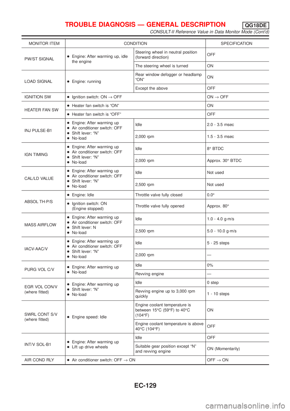
MONITOR ITEM CONDITION SPECIFICATION
PW/ST SIGNAL+Engine: After warming up, idle
the engineSteering wheel in neutral position
(forward direction)OFF
The steering wheel is turned ON
LOAD SIGNAL+Engine: runningRear window defogger or headlamp
ªONºON
Except the above OFF
IGNITION SW+Ignition switch: ON®OFF ON®OFF
HEATER FAN SW+Heater fan switch is ªONº ON
+Heater fan switch is ªOFFº OFF
INJ PULSE-B1+Engine: After warming up
+Air conditioner switch: OFF
+Shift lever: ªNº
+No-loadIdle 2.0 - 3.5 msec
2,000 rpm 1.5 - 3.5 msec
IGN TIMING+Engine: After warming up
+Air conditioner switch: OFF
+Shift lever: ªNº
+No-loadIdle 8É BTDC
2,000 rpm Approx. 30É BTDC
CAL/LD VALUE+Engine: After warming up
+Air conditioner switch: OFF
+Shift lever: ªNº
+No-loadIdle Not used
2,500 rpm Not used
ABSOL TH´P/S+Engine: Idle Throttle valve fully closed 0.0É
+Ignition switch: ON
(Engine stopped)Throttle valve fully opened Approx. 80É
MASS AIRFLOW+Engine: After warming up
+Air conditioner switch: OFF
+Shift lever: N
+No-loadIdle 1.0 - 4.0 g´m/s
2,500 rpm 5.0 - 10.0 g´m/s
IACV-AAC/V+Engine: After warming up
+Air conditioner switch: OFF
+Shift lever: ªNº
+No-loadIdle 5 - 25 steps
2,000 rpm Ð
PURG VOL C/V+Engine: After warming up
+No-loadIdle 0%
Revving engine Ð
EGR VOL CON/V
(where fitted)+Engine: After warming up
+Shift lever: ªNº
+No-loadIdle 0 step
Revving engine up to 3,000 rpm
quickly1 - 10 steps
SWRL CONT S/V
(where fitted)+Engine speed: IdleEngine coolant temperature is
between 15ÉC (59ÉF) to 40ÉC
(104ÉF)ON
Engine coolant temperature is above
40ÉC (104ÉF)OFF
INT/V SOL-B1+Engine: After warming up
+Lift up drive wheelsIdle OFF
Suitable gear position except ªNº
and revving engineON (Momentarily)
AIR COND RLY+Air conditioner switch: OFF®ON OFF®ON
TROUBLE DIAGNOSIS Ð GENERAL DESCRIPTIONQG18DE
CONSULT-II Reference Value in Data Monitor Mode (Cont'd)
EC-129
Page 562 of 3051
![NISSAN ALMERA TINO 2001 Service Repair Manual TERMI-
NAL
NO.WIRE
COLORITEM CONDITION DATA (DC Voltage)
35
36
37
38L/W
PU
L/R
GY/RIgnition signal (No. 1)
Ignition signal (No. 2)
Ignition signal (No. 3)
Ignition signal (No. 4)[Engine is running]
+W NISSAN ALMERA TINO 2001 Service Repair Manual TERMI-
NAL
NO.WIRE
COLORITEM CONDITION DATA (DC Voltage)
35
36
37
38L/W
PU
L/R
GY/RIgnition signal (No. 1)
Ignition signal (No. 2)
Ignition signal (No. 3)
Ignition signal (No. 4)[Engine is running]
+W](/manual-img/5/57352/w960_57352-561.png)
TERMI-
NAL
NO.WIRE
COLORITEM CONDITION DATA (DC Voltage)
35
36
37
38L/W
PU
L/R
GY/RIgnition signal (No. 1)
Ignition signal (No. 2)
Ignition signal (No. 3)
Ignition signal (No. 4)[Engine is running]
+Warm-up condition
+Idle speed0 - 0.2V
SEF971W
[Engine is running]
+Engine speed is 2,000 rpm0.2 - 0.4V
SEF972W
40 Y/PUThrottle position switch
(Closed position)
(where fitted)[Engine is running]
+Accelerator pedal releasedBATTERY VOLTAGE
(11 - 14V)
[Engine is running]
+Accelerator pedal depressedApproximately 0V
41 B/Y Start signal[Ignition switch ªONº]Approximately 0V
[Ignition switch ªSTARTº]9 - 12V
42 G/OR PNP switch[Ignition switch ªONº]
+Gear position is ªNeutral positionºApproximately 0V
[Ignition switch ªONº]
+Except the above gear positionApproximately 5V
43 B/R Ignition switch[Ignition switch ªOFFº]0V
[Ignition switch ªONº]BATTERY VOLTAGE
(11 - 14V)
44 L/R Air conditioner switch[Engine is running]
+Both air conditioner switch and blower switch
are ªONº (Compressor operates)Approximately 0V
[Engine is running]
+Air conditioner switch is ªOFFºApproximately 5V
46 PU/WPower steering oil pres-
sure switch[Engine is running]
+Steering wheel is fully turnedApproximately 0V
[Engine is running]
+Steering wheel is not turnedApproximately 5V
48 B ECM ground[Engine is running]
+Idle speedEngine ground
50 L/BElectrical load signal
(Headlamp and
Rear defogger)[Engine is running]
+Headlamp switch or rear defogger switch is
ªONºBATTERY VOLTAGE
(11 - 14V)
[Engine is running]
+Headlamp switch and rear defogger switch are
ªOFFºApproximately 0V
TROUBLE DIAGNOSIS Ð GENERAL DESCRIPTIONQG18DE
ECM Terminals and Reference Value (Cont'd)
EC-137
Page 566 of 3051
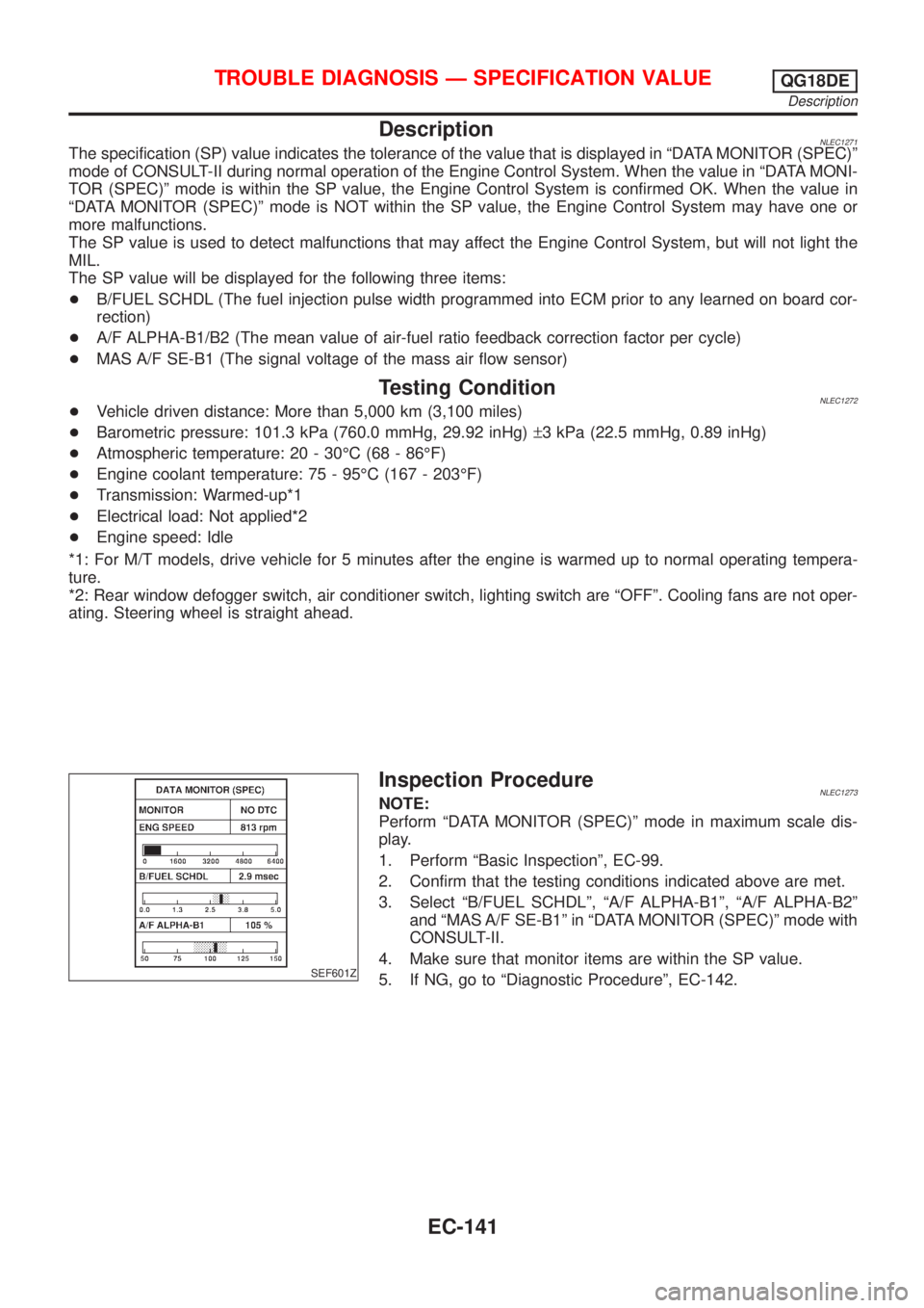
DescriptionNLEC1271The specification (SP) value indicates the tolerance of the value that is displayed in ªDATA MONITOR (SPEC)º
mode of CONSULT-II during normal operation of the Engine Control System. When the value in ªDATA MONI-
TOR (SPEC)º mode is within the SP value, the Engine Control System is confirmed OK. When the value in
ªDATA MONITOR (SPEC)º mode is NOT within the SP value, the Engine Control System may have one or
more malfunctions.
The SP value is used to detect malfunctions that may affect the Engine Control System, but will not light the
MIL.
The SP value will be displayed for the following three items:
+B/FUEL SCHDL (The fuel injection pulse width programmed into ECM prior to any learned on board cor-
rection)
+A/F ALPHA-B1/B2 (The mean value of air-fuel ratio feedback correction factor per cycle)
+MAS A/F SE-B1 (The signal voltage of the mass air flow sensor)
Testing ConditionNLEC1272+Vehicle driven distance: More than 5,000 km (3,100 miles)
+Barometric pressure: 101.3 kPa (760.0 mmHg, 29.92 inHg)±3 kPa (22.5 mmHg, 0.89 inHg)
+Atmospheric temperature: 20 - 30ÉC (68 - 86ÉF)
+Engine coolant temperature: 75 - 95ÉC (167 - 203ÉF)
+Transmission: Warmed-up*1
+Electrical load: Not applied*2
+Engine speed: Idle
*1: For M/T models, drive vehicle for 5 minutes after the engine is warmed up to normal operating tempera-
ture.
*2: Rear window defogger switch, air conditioner switch, lighting switch are ªOFFº. Cooling fans are not oper-
ating. Steering wheel is straight ahead.
SEF601Z
Inspection ProcedureNLEC1273NOTE:
Perform ªDATA MONITOR (SPEC)º mode in maximum scale dis-
play.
1. Perform ªBasic Inspectionº, EC-99.
2. Confirm that the testing conditions indicated above are met.
3. Select ªB/FUEL SCHDLº, ªA/F ALPHA-B1º, ªA/F ALPHA-B2º
and ªMAS A/F SE-B1º in ªDATA MONITOR (SPEC)º mode with
CONSULT-II.
4. Make sure that monitor items are within the SP value.
5. If NG, go to ªDiagnostic Procedureº, EC-142.
TROUBLE DIAGNOSIS Ð SPECIFICATION VALUEQG18DE
Description
EC-141
Page 773 of 3051
3 CHECK OUTPUT SIGNAL CIRCUIT
1. Turn ignition switch ªOFFº.
2. Disconnect ECM harness connector.
3. Check harness continuity between
ECM terminal 6 and IACV-AAC valve terminal 1,
ECM terminal 7 and IACV-AAC valve terminal 4,
ECM terminal 15 and IACV-AAC valve terminal 3,
ECM terminal 16 and IACV-AAC valve terminal 6.
Refer to wiring diagram.
Continuity should exist.
4. Also check harness for short to ground and short to power.
OK or NG
OK©GO TO 4.
NG©Repair open circuit or short to ground or short to power in harness or connectors.
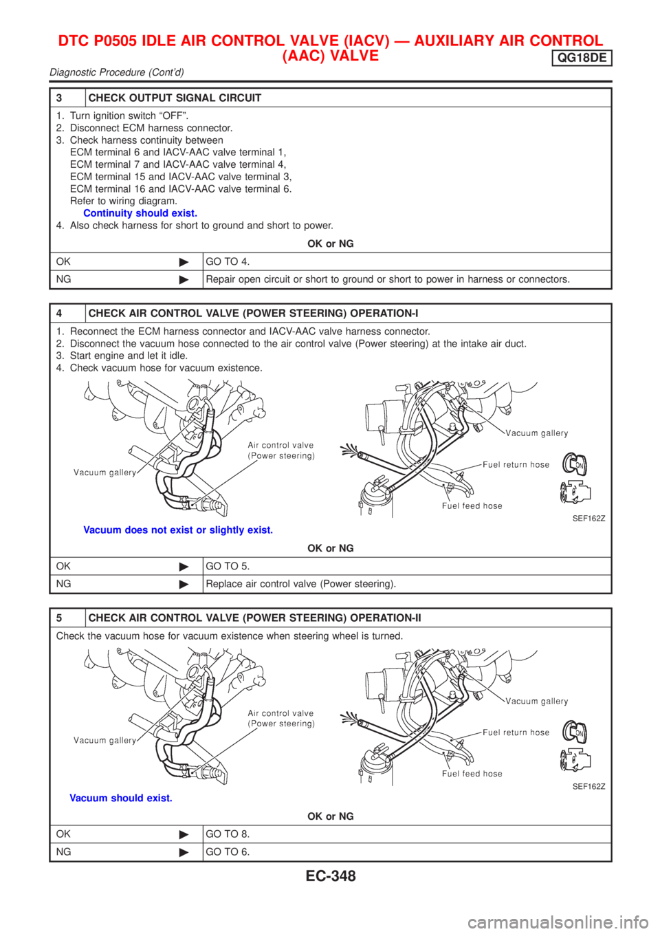
4 CHECK AIR CONTROL VALVE (POWER STEERING) OPERATION-I
1. Reconnect the ECM harness connector and IACV-AAC valve harness connector.
2. Disconnect the vacuum hose connected to the air control valve (Power steering) at the intake air duct.
3. Start engine and let it idle.
4. Check vacuum hose for vacuum existence.
SEF162Z
Vacuum does not exist or slightly exist.
OK or NG
OK©GO TO 5.
NG©Replace air control valve (Power steering).
5 CHECK AIR CONTROL VALVE (POWER STEERING) OPERATION-II
Check the vacuum hose for vacuum existence when steering wheel is turned.
SEF162Z
Vacuum should exist.
OK or NG
OK©GO TO 8.
NG©GO TO 6.
DTC P0505 IDLE AIR CONTROL VALVE (IACV) Ð AUXILIARY AIR CONTROL
(AAC) VALVE
QG18DE
Diagnostic Procedure (Cont'd)
EC-348
Page 897 of 3051
6 CHECK AIR CONTROL VALVE (POWER STEERING) OPERATION-II
Check the vacuum hose for vacuum existence when steering wheel is turned.
SEF162Z
Vacuum should exist.
OK or NG
OK©GO TO 9.
NG©GO TO 7.
7 CHECK VACUUM PORT
1. Stop engine.
2. Disconnect the vacuum hose connected to the air control valve (Power steering) at the vacuum port.
3. Blow air into vacuum port.
4. Check that air flows freely.
SEF924Y
OK or NG
OK©GO TO 8.
NG©Repair or clean vacuum port.
IDLE AIR CONTROL VALVE (IACV) Ð
AUXILIARY AIR CONTROL (AAC) VALVE
QG18DE
Diagnostic Procedure (Cont'd)
EC-472
Page 948 of 3051
JEF137Y
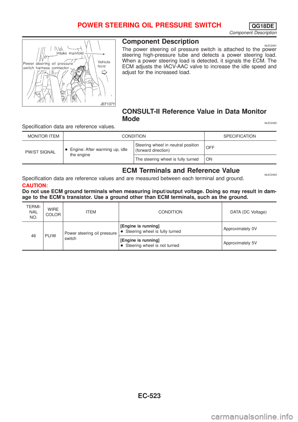
Component DescriptionNLEC0451The power steering oil pressure switch is attached to the power
steering high-pressure tube and detects a power steering load.
When a power steering load is detected, it signals the ECM. The
ECM adjusts the IACV-AAC valve to increase the idle speed and
adjust for the increased load.
CONSULT-II Reference Value in Data Monitor
Mode
NLEC0452Specification data are reference values.
MONITOR ITEM CONDITION SPECIFICATION
PW/ST SIGNAL+Engine: After warming up, idle
the engineSteering wheel in neutral position
(forward direction)OFF
The steering wheel is fully turned ON
ECM Terminals and Reference ValueNLEC0453Specification data are reference values and are measured between each terminal and ground.
CAUTION:
Do not use ECM ground terminals when measuring input/output voltage. Doing so may result in dam-
age to the ECM's transistor. Use a ground other than ECM terminals, such as the ground.
TERMI-
NAL
NO.WIRE
COLORITEM CONDITION DATA (DC Voltage)
46 PU/WPower steering oil pressure
switch[Engine is running]
+Steering wheel is fully turnedApproximately 0V
[Engine is running]
+Steering wheel is not turnedApproximately 5V
POWER STEERING OIL PRESSURE SWITCHQG18DE
Component Description
EC-523