2001 NISSAN ALMERA TINO schematic relay
[x] Cancel search: schematic relayPage 239 of 3051

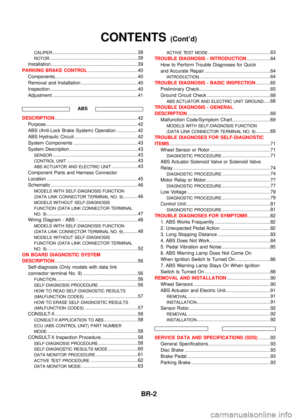
CALIPER.................................................................38
ROTOR...................................................................39
Installation ..................................................................39
PARKING BRAKE CONTROL......................................40
Components...............................................................40
Removal and Installation ...........................................40
Inspection...................................................................40
Adjustment .................................................................41
ABS
DESCRIPTION...............................................................42
Purpose......................................................................42
ABS (Anti-Lock Brake System) Operation ................42
ABS Hydraulic Circuit ................................................42
System Components .................................................43
System Description ....................................................43
SENSOR.................................................................43
CONTROL UNIT......................................................43
ABS ACTUATOR AND ELECTRIC UNIT....................43
Component Parts and Harness Connector
Location .....................................................................45
Schematic ..................................................................46
MODELS WITH SELF-DIAGNOSIS FUNCTION
(DATA LINK CONNECTOR TERMINAL NO. 9)
...........46
MODELS WITHOUT SELF-DIAGNOSIS
FUNCTION (DATA LINK CONNECTOR TERMINAL
NO. 9)
.....................................................................47
Wiring Diagram - ABS - .............................................48
MODELS WITH SELF-DIAGNOSIS FUNCTION
(DATA LINK CONNECTOR TERMINAL NO. 9)
...........48
MODELS WITHOUT SELF-DIAGNOSIS
FUNCTION (DATA LINK CONNECTOR TERMINAL
NO. 9)
.....................................................................52
ON BOARD DIAGNOSTIC SYSTEM
DESCRIPTION...............................................................56
Self-diagnosis (Only models with data link
connector terminal No. 9) ..........................................56
FUNCTION..............................................................56
SELF-DIAGNOSIS PROCEDURE..............................56
HOW TO READ SELF-DIAGNOSTIC RESULTS
(MALFUNCTION CODES)
........................................57
HOW TO ERASE SELF-DIAGNOSTIC RESULTS
(MALFUNCTION CODES)
........................................57
CONSULT-II ...............................................................58
CONSULT-II APPLICATION TO ABS..........................58
ECU (ABS CONTROL UNIT) PART NUMBER
MODE
.....................................................................58
CONSULT-II Inspection Procedure............................58
SELF-DIAGNOSIS PROCEDURE..............................58
SELF-DIAGNOSTIC RESULTS MODE.......................60
DATA MONITOR PROCEDURE................................61
ACTIVE TEST PROCEDURE....................................62
DATA MONITOR MODE...........................................63
ACTIVE TEST MODE...............................................63
TROUBLE DIAGNOSIS - INTRODUCTION..................64
How to Perform Trouble Diagnoses for Quick
and Accurate Repair ..................................................64
INTRODUCTION......................................................64
TROUBLE DIAGNOSIS - BASIC INSPECTION...........65
Preliminary Check......................................................65
Ground Circuit Check ................................................68
ABS ACTUATOR AND ELECTRIC UNIT GROUND.....68
TROUBLE DIAGNOSIS - GENERAL
DESCRIPTION...............................................................69
Malfunction Code/Symptom Chart.............................69
MODELS WITH SELF-DIAGNOSIS FUNCTION
(DATA LINK CONNECTOR TERMINAL NO. 9)
...........69
TROUBLE DIAGNOSES FOR SELF-DIAGNOSTIC
ITEMS.............................................................................71
Wheel Sensor or Rotor ..............................................71
DIAGNOSTIC PROCEDURE.....................................71
ABS Actuator Solenoid Valve or Solenoid Valve
Relay ..........................................................................74
DIAGNOSTIC PROCEDURE.....................................74
Motor Relay or Motor.................................................77
DIAGNOSTIC PROCEDURE.....................................77
Low Voltage ...............................................................79
DIAGNOSTIC PROCEDURE.....................................79
Control Unit ................................................................81
DIAGNOSTIC PROCEDURE.....................................81
TROUBLE DIAGNOSES FOR SYMPTOMS.................82
1. ABS Works Frequently ..........................................82
2. Unexpected Pedal Action ......................................82
3. Long Stopping Distance ........................................83
4. ABS Does Not Work ..............................................84
5. Pedal Vibration and Noise.....................................85
6. ABS Warning Lamp Does Not Come On
When Ignition Switch Is Turned On...........................86
7. ABS Warning Lamp Stays On When Ignition
Switch Is Turned On ..................................................88
REMOVAL AND INSTALLATION.................................90
Wheel Sensors ..........................................................90
ABS Actuator and Electric Unit..................................91
REMOVAL...............................................................91
INSTALLATION........................................................91
Sensor Rotor..............................................................92
REMOVAL...............................................................92
INSTALLATION........................................................92
SERVICE DATA AND SPECIFICATIONS (SDS).........93
General Specifications ...............................................93
Disc Brake .................................................................93
Brake Pedal ...............................................................93
Parking Brake ............................................................93
CONTENTS(Cont’d)
BR-2
Page 1732 of 3051

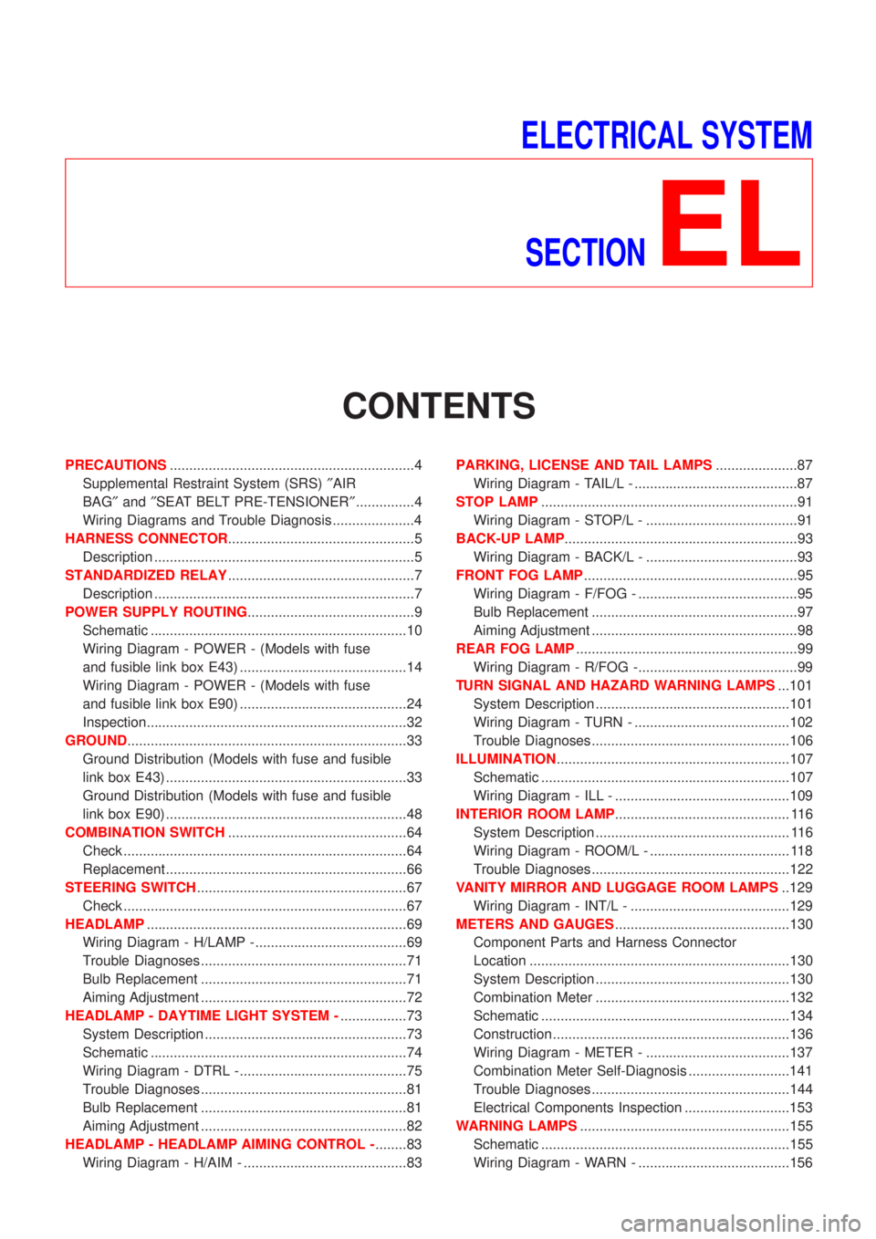
ELECTRICAL SYSTEM
SECTION
EL
CONTENTS
PRECAUTIONS...............................................................4
Supplemental Restraint System (SRS)²AIR
BAG²and²SEAT BELT PRE-TENSIONER²...............4
Wiring Diagrams and Trouble Diagnosis .....................4
HARNESS CONNECTOR................................................5
Description ...................................................................5
STANDARDIZED RELAY................................................7
Description ...................................................................7
POWER SUPPLY ROUTING...........................................9
Schematic ..................................................................10
Wiring Diagram - POWER - (Models with fuse
and fusible link box E43) ...........................................14
Wiring Diagram - POWER - (Models with fuse
and fusible link box E90) ...........................................24
Inspection...................................................................32
GROUND........................................................................33
Ground Distribution (Models with fuse and fusible
link box E43) ..............................................................33
Ground Distribution (Models with fuse and fusible
link box E90) ..............................................................48
COMBINATION SWITCH..............................................64
Check .........................................................................64
Replacement ..............................................................66
STEERING SWITCH......................................................67
Check .........................................................................67
HEADLAMP...................................................................69
Wiring Diagram - H/LAMP -.......................................69
Trouble Diagnoses.....................................................71
Bulb Replacement .....................................................71
Aiming Adjustment .....................................................72
HEADLAMP - DAYTIME LIGHT SYSTEM -.................73
System Description ....................................................73
Schematic ..................................................................74
Wiring Diagram - DTRL - ...........................................75
Trouble Diagnoses.....................................................81
Bulb Replacement .....................................................81
Aiming Adjustment .....................................................82
HEADLAMP - HEADLAMP AIMING CONTROL -........83
Wiring Diagram - H/AIM - ..........................................83PARKING, LICENSE AND TAIL LAMPS.....................87
Wiring Diagram - TAIL/L - ..........................................87
STOP LAMP..................................................................91
Wiring Diagram - STOP/L - .......................................91
BACK-UP LAMP............................................................93
Wiring Diagram - BACK/L - .......................................93
FRONT FOG LAMP.......................................................95
Wiring Diagram - F/FOG - .........................................95
Bulb Replacement .....................................................97
Aiming Adjustment .....................................................98
REAR FOG LAMP.........................................................99
Wiring Diagram - R/FOG -.........................................99
TURN SIGNAL AND HAZARD WARNING LAMPS...101
System Description ..................................................101
Wiring Diagram - TURN - ........................................102
Trouble Diagnoses...................................................106
ILLUMINATION............................................................107
Schematic ................................................................107
Wiring Diagram - ILL - .............................................109
INTERIOR ROOM LAMP............................................. 116
System Description .................................................. 116
Wiring Diagram - ROOM/L - .................................... 118
Trouble Diagnoses...................................................122
VANITY MIRROR AND LUGGAGE ROOM LAMPS..129
Wiring Diagram - INT/L - .........................................129
METERS AND GAUGES.............................................130
Component Parts and Harness Connector
Location ...................................................................130
System Description ..................................................130
Combination Meter ..................................................132
Schematic ................................................................134
Construction .............................................................136
Wiring Diagram - METER - .....................................137
Combination Meter Self-Diagnosis ..........................141
Trouble Diagnoses...................................................144
Electrical Components Inspection ...........................153
WARNING LAMPS......................................................155
Schematic ................................................................155
Wiring Diagram - WARN - .......................................156
Page 2564 of 3051

TESTING FOR“OPENS”IN THE CIRCUITNLGI0005S0302Before you begin to diagnose and test the system, you should
rough sketch a schematic of the system. This will help you to logi-
cally walk through the diagnoses process. Drawing the sketch will
also reinforce your working knowledge of the system.
SGI846
Continuity Check Method
The continuity check is used to find an open in the circuit. The
Digital Multimeter (DMM) set on the resistance function will indicate
an open circuit as over limit (no beep tone or no ohms symbol).
Make sure to always start with the DMM at the highest resistance
level.
To help in understanding the diagnoses of open circuits please
refer to the schematic above.
1) Disconnect the battery negative cable.
2) Start at one end of the circuit and work your way to the other
end. (At the fuse block in this example)
3) Connect one probe of the DMM to the fuse block terminal on
the load side.
4) Connect the other probe to the fuse block (power) side of SW1.
Little or no resistance will indicate that portion of the circuit has
good continuity. If there were an open in the circuit, the DMM
would indicate an over limit or infinite resistance condition.
(point A)
5) Connect the probes between SW1 and the relay. Little or no
resistance will indicate that portion of the circuit has good con-
tinuity. If there were an open in the circuit, the DMM would
indicate an over limit or infinite resistance condition. (point B)
6) Connect the probes between the relay and the solenoid. Little
or no resistance will indicate that portion of the circuit has good
continuity. If there were an open in the circuit, the DMM would
indicate an over limit or infinite resistance condition. (point C)
Any circuit can be diagnosed using the approach in the above
example.
Voltage Check Method
To help in understanding the diagnoses of open circuits please
refer to the previous schematic.
In any powered circuit, an open can be found by methodically
checking the system for the presence of voltage. This is done by
switching the DMM to the voltage function.
1) Connect one probe of the DMM to a known good ground.
2) Begin probing at one end of the circuit and work your way to
the other end.
3) With SW1 open, probe at SW1 to check for voltage.
voltage; open is further down the circuit than SW1.
no voltage; open is between fuse block and SW1 (point A).
4) Close SW1 and probe at relay.
HOW TO PERFORM EFFICIENT DIAGNOSES FOR AN ELECTRICAL INCIDENT
Circuit Inspection (Cont’d)
GI-25
Page 2565 of 3051

voltage; open is further down the circuit than the relay.
no voltage; open is between SW1 and relay (point B).
5) Close the relay and probe at the solenoid.
voltage; open is further down the circuit than the solenoid.
no voltage; open is between relay and solenoid (point C).
Any powered circuit can be diagnosed using the approach in the
above example.
TESTING FOR“SHORTS”IN THE CIRCUITNLGI0005S0303To simplify the discussion of shorts in the system please refer to
the schematic below.
SGI847
Resistance Check Method
1) Disconnect the battery negative cable and remove the blown
fuse.
2) Disconnect all loads (SW1 open, relay disconnected and sole-
noid disconnected) powered through the fuse.
3) Connect one probe of the ohmmeter to the load side of the fuse
terminal. Connect the other probe to a known good ground.
4) With SW1 open, check for continuity.
continuity; short is between fuse terminal and SW1 (point A).
no continuity; short is further down the circuit than SW1.
5) Close SW1 and disconnect the relay. Put probes at the load
side of fuse terminal and a known good ground. Then, check
for continuity.
continuity; short is between SW1 and the relay (point B).
no continuity; short is further down the circuit than the relay.
6) Close SW1 and jump the relay contacts with jumper wire. Put
probes at the load side of fuse terminal and a known good
ground. Then, check for continuity.
continuity; short is between relay and solenoid (point C).
no continuity; check solenoid, retrace steps.
Voltage Check Method
1) Remove the blown fuse and disconnect all loads (i.e. SW1
open, relay disconnected and solenoid disconnected) powered
through the fuse.
2) Turn the ignition key to the ON or START position. Verify bat-
tery voltage at the B + side of the fuse terminal (one lead on
the B + terminal side of the fuse block and one lead on a known
good ground).
3) With SW1 open and the DMM leads across both fuse
terminals, check for voltage.
voltage; short is between fuse block and SW1 (point A).
no voltage; short is further down the circuit than SW1.
4) With SW1 closed, relay and solenoid disconnected and the
DMM leads across both fuse terminals, check for voltage.
voltage; short is between SW1 and the relay (point B).
HOW TO PERFORM EFFICIENT DIAGNOSES FOR AN ELECTRICAL INCIDENT
Circuit Inspection (Cont’d)
GI-26