2001 NISSAN ALMERA TINO checking oil
[x] Cancel search: checking oilPage 52 of 3051
SAT767B
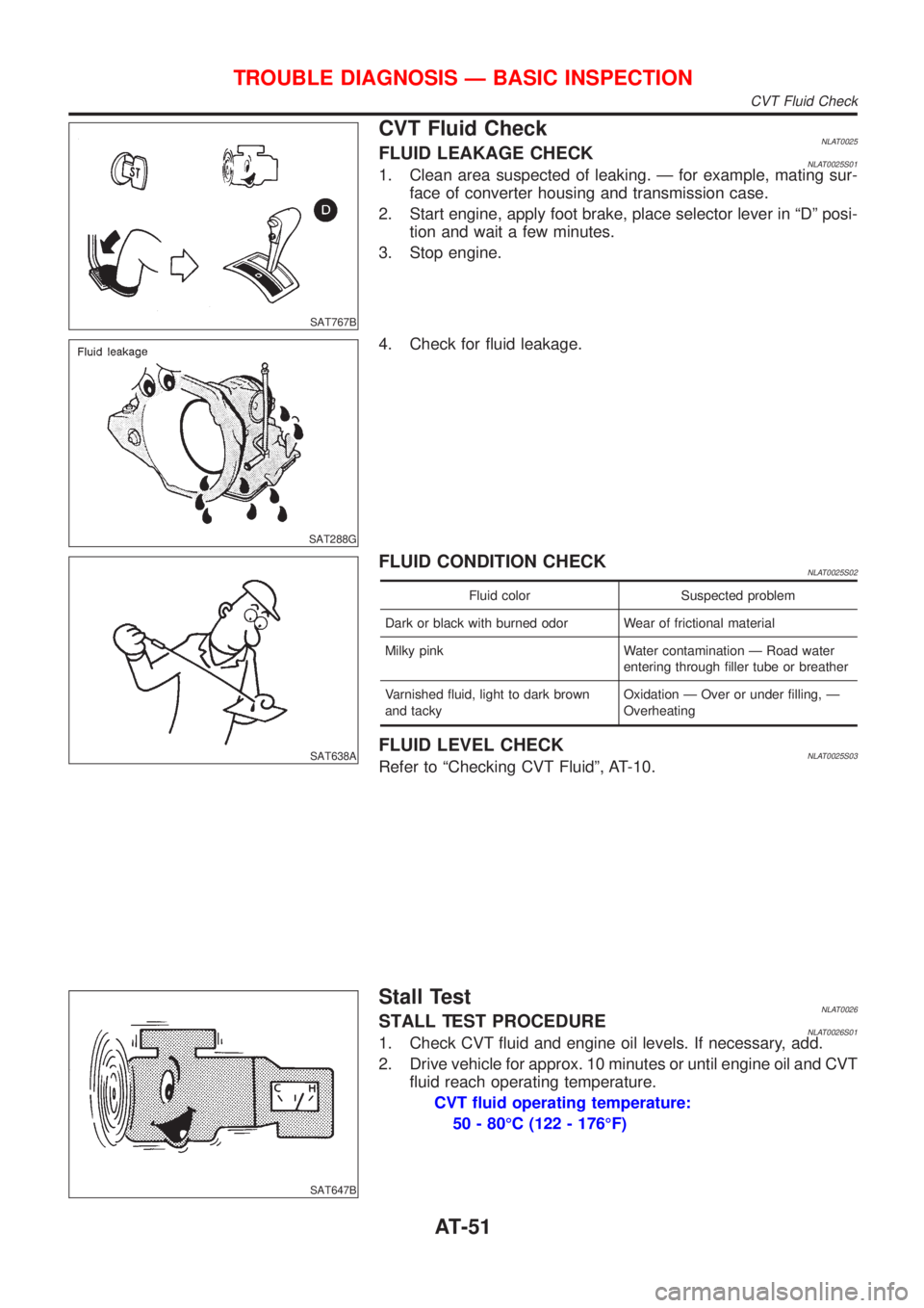
CVT Fluid CheckNLAT0025FLUID LEAKAGE CHECKNLAT0025S011. Clean area suspected of leaking. Ð for example, mating sur-
face of converter housing and transmission case.
2. Start engine, apply foot brake, place selector lever in ªDº posi-
tion and wait a few minutes.
3. Stop engine.
SAT288G
4. Check for fluid leakage.
SAT638A
FLUID CONDITION CHECKNLAT0025S02
Fluid color Suspected problem
Dark or black with burned odor Wear of frictional material
Milky pink Water contamination Ð Road water
entering through filler tube or breather
Varnished fluid, light to dark brown
and tackyOxidation Ð Over or under filling, Ð
Overheating
FLUID LEVEL CHECKNLAT0025S03Refer to ªChecking CVT Fluidº, AT-10.
SAT647B
Stall TestNLAT0026STALL TEST PROCEDURENLAT0026S011. Check CVT fluid and engine oil levels. If necessary, add.
2. Drive vehicle for approx. 10 minutes or until engine oil and CVT
fluid reach operating temperature.
CVT fluid operating temperature:
50 - 80ÉC (122 - 176ÉF)
TROUBLE DIAGNOSIS Ð BASIC INSPECTION
CVT Fluid Check
AT-51
Page 244 of 3051
NBR376
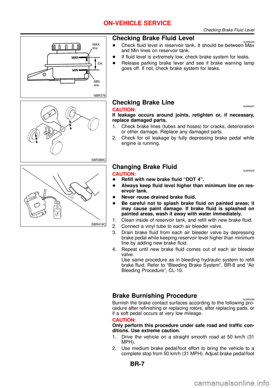
Checking Brake Fluid LevelNLBR0006+Check fluid level in reservoir tank. It should be between Max
and Min lines on reservoir tank.
+If fluid level is extremely low, check brake system for leaks.
+Release parking brake lever and see if brake warning lamp
goes off. If not, check brake system for leaks.
SBR389C
Checking Brake LineNLBR0007CAUTION:
If leakage occurs around joints, retighten or, if necessary,
replace damaged parts.
1. Check brake lines (tubes and hoses) for cracks, deterioration
or other damage. Replace any damaged parts.
2. Check for oil leakage by fully depressing brake pedal while
engine is running.
SBR419C
Changing Brake FluidNLBR0008CAUTION:
+Refill with new brake fluid“DOT 4”.
+Always keep fluid level higher than minimum line on res-
ervoir tank.
+Never reuse drained brake fluid.
+Be careful not to splash brake fluid on painted areas; it
may cause paint damage. If brake fluid is splashed on
painted areas, wash it away with water immediately.
1. Clean inside of reservoir tank, and refill with new brake fluid.
2. Connect a vinyl tube to each air bleeder valve.
3. Drain brake fluid from each air bleeder valve by depressing
brake pedal while keeping reservoir level higher than minimum
line by adding new brake fluid.
4. Repeat until new brake fluid comes out of each air bleeder
valve.
Use same procedure as in bleeding hydraulic system to refill
brake fluid. Refer to“Bleeding Brake System”, BR-8 and“Air
Bleeding Procedure”, CL-10.
Brake Burnishing ProcedureNLBR0036Burnish the brake contact surfaces according to the following pro-
cedure after refinishing or replacing rotors, after replacing pads, or
if a soft pedal occurs at very low mileage.
CAUTION:
Only perform this procedure under safe road and traffic con-
ditions. Use extreme caution.
1. Drive the vehicle on a straight smooth road at 50 km/h (31
MPH).
2. Use medium brake pedal/foot effort to bring the vehicle to a
complete stop from 50 km/h (31 MPH). Adjust brake pedal/foot
ON-VEHICLE SERVICE
Checking Brake Fluid Level
BR-7
Page 713 of 3051
6 CHECK IGNITION SPARK
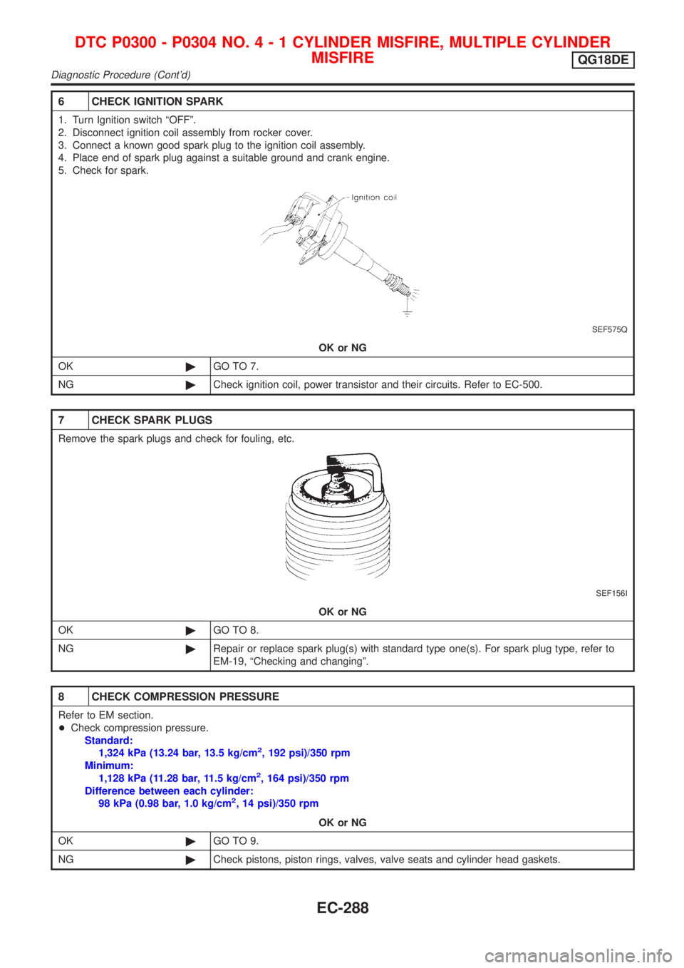
1. Turn Ignition switch ªOFFº.
2. Disconnect ignition coil assembly from rocker cover.
3. Connect a known good spark plug to the ignition coil assembly.
4. Place end of spark plug against a suitable ground and crank engine.
5. Check for spark.
SEF575Q
OK or NG
OK©GO TO 7.
NG©Check ignition coil, power transistor and their circuits. Refer to EC-500.
7 CHECK SPARK PLUGS
Remove the spark plugs and check for fouling, etc.
SEF156I
OK or NG
OK©GO TO 8.
NG©Repair or replace spark plug(s) with standard type one(s). For spark plug type, refer to
EM-19, ªChecking and changingº.
8 CHECK COMPRESSION PRESSURE
Refer to EM section.
+Check compression pressure.
Standard:
1,324 kPa (13.24 bar, 13.5 kg/cm
2, 192 psi)/350 rpm
Minimum:
1,128 kPa (11.28 bar, 11.5 kg/cm
2, 164 psi)/350 rpm
Difference between each cylinder:
98 kPa (0.98 bar, 1.0 kg/cm
2, 14 psi)/350 rpm
OK or NG
OK©GO TO 9.
NG©Check pistons, piston rings, valves, valve seats and cylinder head gaskets.
DTC P0300 - P0304 NO.4-1CYLINDER MISFIRE, MULTIPLE CYLINDER
MISFIRE
QG18DE
Diagnostic Procedure (Cont'd)
EC-288
Page 1332 of 3051
8 CHECK RESISTOR
Refer to ªComponent Inspectionº EC-908.
OK or NG
OK©GO TO 9.
NG©Replace distributor cap.
9 CHECK INTERMITTENT INCIDENT
Perform ªTROUBLE DIAGNOSIS FOR INTERMITTENT INCIDENTº, EC-670.
©INSPECTION END
SEF237X
SEF238X
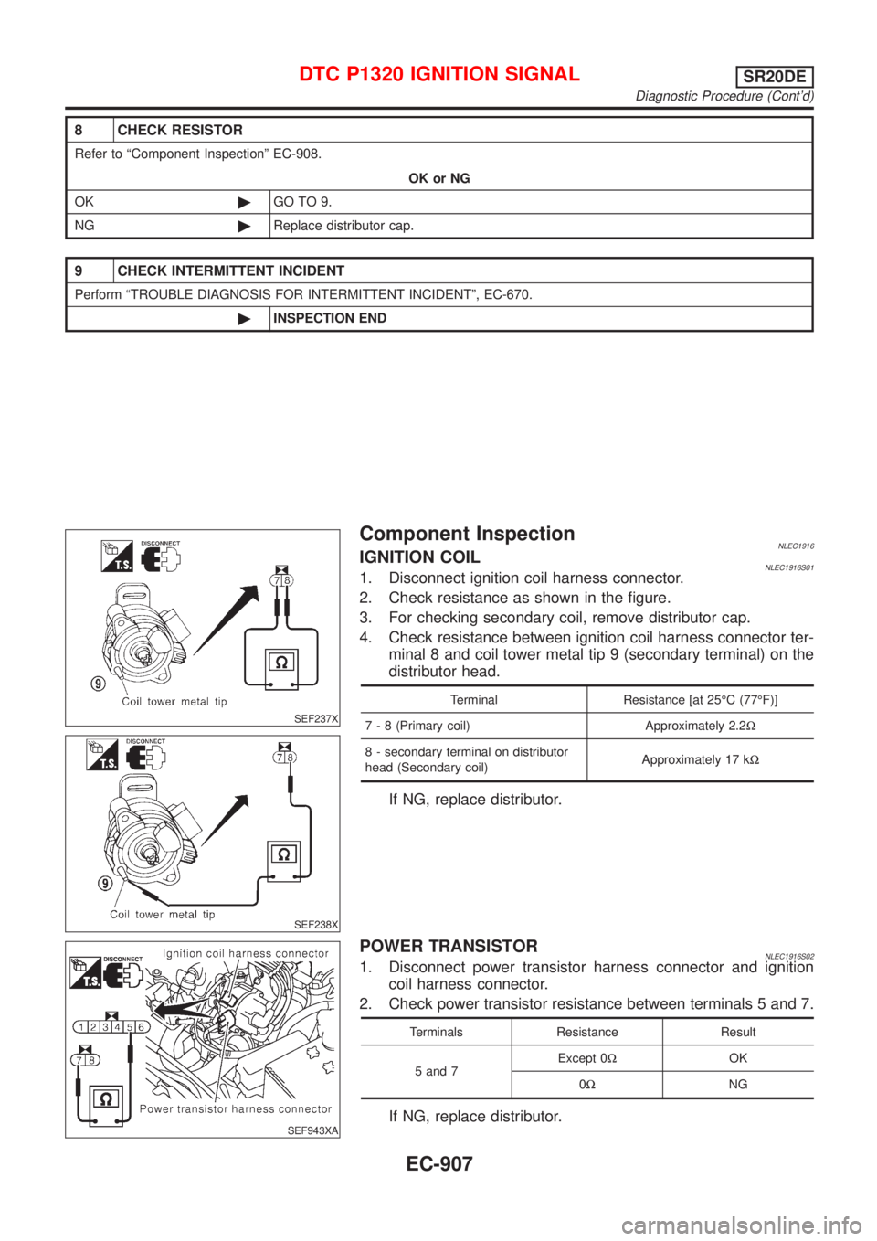
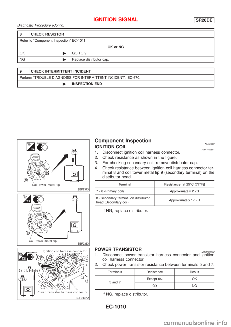
Component InspectionNLEC1916IGNITION COILNLEC1916S011. Disconnect ignition coil harness connector.
2. Check resistance as shown in the figure.
3. For checking secondary coil, remove distributor cap.
4. Check resistance between ignition coil harness connector ter-
minal 8 and coil tower metal tip 9 (secondary terminal) on the
distributor head.
Terminal Resistance [at 25ÉC (77ÉF)]
7 - 8 (Primary coil) Approximately 2.2W
8 - secondary terminal on distributor
head (Secondary coil)Approximately 17 kW
If NG, replace distributor.
SEF943XA
POWER TRANSISTORNLEC1916S021. Disconnect power transistor harness connector and ignition
coil harness connector.
2. Check power transistor resistance between terminals 5 and 7.
Terminals Resistance Result
5 and 7Except 0WOK
0WNG
If NG, replace distributor.
DTC P1320 IGNITION SIGNALSR20DE
Diagnostic Procedure (Cont'd)
EC-907
Page 1435 of 3051
8 CHECK RESISTOR
Refer to ªComponent Inspectionº EC-1011.
OK or NG
OK©GO TO 9.
NG©Replace distributor cap.
9 CHECK INTERMITTENT INCIDENT
Perform ªTROUBLE DIAGNOSIS FOR INTERMITTENT INCIDENTº, EC-670.
©INSPECTION END
SEF237X
SEF238X
Component InspectionNLEC1929IGNITION COILNLEC1929S011. Disconnect ignition coil harness connector.
2. Check resistance as shown in the figure.
3. For checking secondary coil, remove distributor cap.
4. Check resistance between ignition coil harness connector ter-
minal 8 and coil tower metal tip 9 (secondary terminal) on the
distributor head.
Terminal Resistance [at 25ÉC (77ÉF)]
7 - 8 (Primary coil) Approximately 2.2W
8 - secondary terminal on distributor
head (Secondary coil)Approximately 17 kW
If NG, replace distributor.
SEF943XA
POWER TRANSISTORNLEC1929S021. Disconnect power transistor harness connector and ignition
coil harness connector.
2. Check power transistor resistance between terminals 5 and 7.
Terminals Resistance Result
5 and 7Except 0WOK
0WNG
If NG, replace distributor.
IGNITION SIGNALSR20DE
Diagnostic Procedure (Cont'd)
EC-1010
Page 2258 of 3051
ENGINE MECHANICAL
SECTION
EM
CONTENTS
QG
PRECAUTIONS...............................................................5
Parts Requiring Angular Tightening .............................5
Liquid Gasket Application Procedure ..........................5
PREPARATION...............................................................6
Special Service Tools ..................................................6
Commercial Service Tools ...........................................8
NOISE, VIBRATION AND HARSHNESS (NVH)
TROUBLESHOOTING...................................................10
NVH Troubleshooting - Engine Noise .......................10
OUTER COMPONENT PARTS.....................................12
Removal and Installation ...........................................12
MEASUREMENT OF COMPRESSION PRESSURE....16
DRIVE BELTS................................................................17
Checking ....................................................................17
AIR CLEANER...............................................................18
Changing Air Cleaner Filter .......................................18
VISCOUS PAPER TYPE...........................................18
SPARK PLUG................................................................19
Checking and Changing ............................................19
OIL PAN.........................................................................20
Components...............................................................20
Removal .....................................................................20
Installation ..................................................................21
TIMING CHAIN..............................................................22
Components...............................................................22
Removal .....................................................................23
Inspection...................................................................26
Installation ..................................................................27
OIL SEAL.......................................................................31
Replacement ..............................................................31
VALVE OIL SEAL.....................................................31
FRONT OIL SEAL....................................................31
REAR OIL SEAL......................................................32
CYLINDER HEAD..........................................................33
Components...............................................................33
Removal .....................................................................34
Disassembly...............................................................36Inspection...................................................................36
CYLINDER HEAD DISTORTION...............................36
CAMSHAFT VISUAL CHECK....................................36
CAMSHAFT RUNOUT..............................................37
CAMSHAFT CAM HEIGHT.......................................37
CAMSHAFT JOURNAL CLEARANCE........................37
CAMSHAFT END PLAY............................................38
CAMSHAFT SPROCKET RUNOUT...........................38
VALVE GUIDE CLEARANCE....................................38
VALVE GUIDE REPLACEMENT................................39
VALVE SEATS.........................................................40
REPLACING VALVE SEAT FOR SERVICE PARTS....40
VALVE DIMENSIONS...............................................41
VALVE SPRING.......................................................41
VALVE LIFTER AND VALVE SHIM............................41
Valve Clearance.........................................................42
CHECKING.............................................................42
ADJUSTING............................................................43
Assembly ...................................................................45
Installation ..................................................................45
ENGINE ASSEMBLY.....................................................49
Removal and Installation ...........................................49
REMOVAL...............................................................50
INSTALLATION........................................................51
CYLINDER BLOCK.......................................................52
Components...............................................................52
Removal and Installation ...........................................53
Disassembly...............................................................53
PISTON AND CRANKSHAFT....................................53
Inspection...................................................................54
PISTON AND PISTON PIN CLEARANCE..................54
PISTON RING SIDE CLEARANCE............................54
PISTON RING END GAP..........................................54
CONNECTING ROD BEND AND TORSION...............55
CYLINDER BLOCK DISTORTION AND WEAR...........55
PISTON-TO-BORE CLEARANCE..............................56
CRANKSHAFT.........................................................57
BEARING CLEARANCE...........................................57
CONNECTING ROD BUSHING CLEARANCE
(SMALL END)
..........................................................59
Page 2259 of 3051
REPLACEMENT OF CONNECTING ROD
BUSHING (SMALL END)
..........................................60
FLYWHEEL RUNOUT..............................................60
Assembly ...................................................................60
PISTON..................................................................60
CRANKSHAFT.........................................................61
SERVICE DATA AND SPECIFICATIONS (SDS).........64
General Specifications ...............................................64
Compression Pressure ..............................................64
Belt Deflection............................................................64
Spark Plug .................................................................65
Cylinder Head ............................................................65
Valve ..........................................................................65
VALVE....................................................................65
VALVE SPRING.......................................................65
VALVE LIFTER........................................................66
VALVE CLEARANCE................................................67
VALVE GUIDE.........................................................67
AVAILABLE SHIMS..................................................67
VALVE SEAT...........................................................70
VALVE SEAT RESURFACE LIMIT.............................71
Camshaft and Camshaft Bearing ..............................71
Cylinder Block ............................................................72
Piston, Piston Ring and Piston Pin ...........................73
PISTON..................................................................73
PISTON RING.........................................................73
PISTON PIN............................................................73
Connecting Rod .........................................................74
Crankshaft..................................................................74
Main Bearing..............................................................74
STANDARD.............................................................74
UNDERSIZE............................................................74
Connecting Rod Bearing ...........................................75
STANDARD SIZE....................................................75
UNDERSIZE............................................................75
Bearing Clearance .....................................................75
Miscellaneous Components.......................................75
SR
PRECAUTIONS.............................................................76
Parts Requiring Angular Tightening ...........................76
Liquid Gasket Application Procedure ........................76
PREPARATION.............................................................77
Special Service Tools ................................................77
Commercial Service Tools .........................................79
NOISE, VIBRATION AND HARSHNESS (NVH)
TROUBLESHOOTING...................................................80
NVH Troubleshooting - Engine Noise .......................81
OUTER COMPONENT PARTS.....................................82
Removal and Installation ...........................................82
MEASUREMENT OF COMPRESSION PRESSURE....85
DRIVE BELTS................................................................86
Checking ....................................................................86AIR CLEANER...............................................................88
Changing Air Cleaner Filter .......................................88
VISCOUS PAPER TYPE...........................................88
SPARK PLUG................................................................89
Checking and Changing Spark Plugs .......................89
Checking Ignition Leads ............................................90
OIL PAN.........................................................................91
Components...............................................................91
Removal .....................................................................91
Installation ..................................................................93
TIMING CHAIN..............................................................96
Components...............................................................96
Removal .....................................................................97
Inspection.................................................................100
Installation ................................................................100
OIL SEAL.....................................................................105
Replacement ............................................................105
VALVE OIL SEAL...................................................105
FRONT OIL SEAL..................................................105
REAR OIL SEAL....................................................107
CYLINDER HEAD........................................................108
Components.............................................................108
Removal ...................................................................109
Disassembly............................................................. 111
Inspection................................................................. 113
CYLINDER HEAD DISTORTION............................. 113
CAMSHAFT VISUAL CHECK.................................. 114
CAMSHAFT RUNOUT............................................ 114
CAMSHAFT CAM HEIGHT..................................... 114
CAMSHAFT JOURNAL CLEARANCE...................... 115
CAMSHAFT END PLAY.......................................... 115
CAMSHAFT SPROCKET RUNOUT......................... 116
VALVE GUIDE CLEARANCE.................................. 116
VALVE GUIDE REPLACEMENT.............................. 116
VALVE SEATS....................................................... 117
REPLACING VALVE SEAT FOR SERVICE PARTS.. 118
VALVE DIMENSIONS............................................. 119
VALVE SPRING..................................................... 119
HYDRAULIC LASH ADJUSTER.............................. 119
ROCKER ARM, SHIM AND ROCKER ARM GUIDE...120
Assembly .................................................................120
Installation ................................................................123
ENGINE ASSEMBLY...................................................130
Removal and Installation .........................................130
REMOVAL.............................................................131
INSTALLATION......................................................132
CYLINDER BLOCK.....................................................133
Components.............................................................133
Removal and Installation .........................................134
Disassembly.............................................................134
PISTON AND CRANKSHAFT..................................134
Inspection.................................................................134
PISTON AND PISTON PIN CLEARANCE................134
PISTON RING SIDE CLEARANCE..........................135
CONTENTS(Cont'd)
EM-2
Page 2261 of 3051
Components.............................................................200
Removal ...................................................................201
PREPARATIVE WORK...........................................201
CAMSHAFT...........................................................201
CYLINDER HEAD..................................................202
Disassembly.............................................................202
Inspection.................................................................203
CYLINDER HEAD DISTORTION.............................203
CAMSHAFT VISUAL CHECK..................................204
CAMSHAFT RUNOUT............................................204
CAMSHAFT CAM HEIGHT.....................................204
CAMSHAFT JOURNAL CLEARANCE......................204
CAMSHAFT END PLAY..........................................205
CAMSHAFT SPROCKET RUNOUT.........................205
VALVE GUIDE CLEARANCE..................................205
VALVE GUIDE REPLACEMENT..............................206
VALVE SEATS.......................................................207
REPLACING VALVE SEAT FOR SERVICE PARTS..207
VALVE DIMENSIONS.............................................209
VALVE SPRING.....................................................209
VALVE LIFTER......................................................209
Assembly .................................................................210
Installation ................................................................210
CYLINDER HEAD GASKET SELECTION.................210
CYLINDER HEAD BOLT DEFORMATION CHECK... 211
CYLINDER HEAD-TO-BLOCK DIFFERENCE
CHECK
.................................................................212
LIQUID GASKET APPLICATION ON REAR CHAIN
CASE
....................................................................212
CYLINDER HEAD INSTALLATION..........................212
GLOW PLUG INSTALLATION.................................212
CAMSHAFT INSTALLATION...................................213
Valve Clearance.......................................................214
CHECKING...........................................................214
ADJUSTING..........................................................215
ENGINE ASSEMBLY...................................................218
Removal and Installation .........................................218
REMOVAL.............................................................219
INSTALLATION......................................................220
CYLINDER BLOCK.....................................................221
Components.............................................................221
Removal and Installation .........................................222
Disassembly.............................................................222
PISTON AND CRANKSHAFT..................................222
Inspection.................................................................225
CRANKSHAFT END PLAY.....................................225
CONNECTING ROD SIDE CLEARANCE.................225
PISTON AND PISTON PIN CLEARANCE................226
PISTON RING SIDE CLEARANCE..........................226
PISTON RING END GAP........................................226
CONNECTING ROD BEND AND TORSION.............227
CYLINDER BLOCK DISTORTION AND WEAR.........227
PISTON-TO-BORE CLEARANCE............................228
CRANKSHAFT.......................................................229
MAIN BEARING HOUSING INNER DIAMETER........230
BEARING CLEARANCE.........................................230
MAIN BEARING CRUSH HEIGHT...........................234
MAIN BEARING CAP BOLT DEFORMATION...........234
CONNECTING ROD BUSHING CLEARANCE
(SMALL END)
........................................................234
CONNECTING ROD BOLT DEFORMATION............235
FLYWHEEL RUNOUT............................................235
OIL JET................................................................235
OIL JET RELIEF VALVE.........................................235
Assembly .................................................................236
PISTON................................................................236
CRANKSHAFT.......................................................236
REPLACEMENT OF PILOT BUSHING.....................239
SERVICE DATA AND SPECIFICATIONS (SDS).......241
General Specifications .............................................241
Compression Pressure ............................................241
Belt Deflection..........................................................241
Cylinder Head ..........................................................241
Valve ........................................................................242
VALVE..................................................................242
VALVE CLEARANCE..............................................242
AVAILABLE SHIMS................................................242
VALVE SPRING.....................................................243
VALVE LIFTER......................................................243
VALVE GUIDE.......................................................244
Valve Seat................................................................245
Camshaft and Camshaft Bearing ............................247
Cylinder Block ..........................................................248
Piston, Piston Ring and Piston Pin .........................248
AVAILABLE PISTON..............................................248
PISTON RING.......................................................249
PISTON PIN..........................................................249
Connecting Rod .......................................................249
Crankshaft................................................................249
Available Main Bearing ............................................250
UNDERSIZE..........................................................250
Available Connecting Rod Bearing..........................250
CONNECTING ROD BEARING...............................250
UNDERSIZE..........................................................251
Miscellaneous Components.....................................251
BEARING CLEARANCE.........................................251
CONTENTS(Cont'd)
EM-4