2001 NISSAN ALMERA TINO auxiliary battery
[x] Cancel search: auxiliary batteryPage 768 of 3051
DescriptionNLEC0279SYSTEM DESCRIPTIONNLEC0279S01
Sensor Input Signal to ECMECM func-
tionActuator
Crankshaft position sensor (POS) Engine speed
Idle air con-
trolIACV-AAC valve Camshaft position sensor (PHASE) Engine speed and cylinder number
Engine coolant temperature sensor Engine coolant temperature
Ignition switch Start signal
Throttle position sensor Throttle position
PNP switch Park/Neutral position
Air conditioner switch Air conditioner operation
Power steering oil pressure switch Power steering load signal
Battery Battery voltage
Vehicle speed sensor Vehicle speed
Cooling fan Cooling fan operation
Electrical load Electrical load signal
This system automatically controls engine idle speed to a specified
level. Idle speed is controlled through fine adjustment of the
amount of air which by-passes the throttle valve via IACV-AAC
valve. The IACV-AAC valve changes the opening of the air by-pass
passage to control the amount of auxiliary air. This valve is actu-
ated by a step motor built into the valve, which moves the valve in
the axial direction in steps corresponding to the ECM output sig-
nals. One step of IACV-AAC valve movement causes the respec-
tive opening of the air by-pass passage. (i.e. when the step
advances, the opening is enlarged.) The opening of the valve is
varied to allow for optimum control of the engine idling speed. The
crankshaft position sensor (POS) detects the actual engine speed
and sends a signal to the ECM. The ECM then controls the step
position of the IACV-AAC valve so that engine speed coincides with
the target value memorized in ECM. The target engine speed is the
lowest speed at which the engine can operate steadily. The opti-
mum value stored in the ECM is determined by taking into consid-
eration various engine conditions, such as during warm up,
deceleration, and engine load (air conditioner, power steering, cool-
ing fan operation and electrical load).
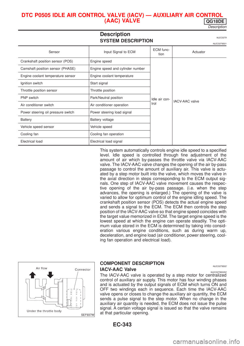
SEF937W
COMPONENT DESCRIPTIONNLEC0279S02IACV-AAC ValveNLEC0279S0202The IACV-AAC valve is operated by a step motor for centralized
control of auxiliary air supply. This motor has four winding phases
and is actuated by the output signals of ECM which turns ON and
OFF two windings each in sequence. Each time the IACV-AAC
valve opens or closes to change the auxiliary air quantity, the ECM
sends a pulse signal to the step motor. When no change in the
auxiliary air quantity is needed, the ECM does not issue the pulse
signal. A certain voltage signal is issued so that the valve remains
at that particular opening.
DTC P0505 IDLE AIR CONTROL VALVE (IACV) Ð AUXILIARY AIR CONTROL
(AAC) VALVE
QG18DE
Description
EC-343
Page 891 of 3051
DescriptionNLEC1305SYSTEM DESCRIPTIONNLEC1305S01
Sensor Input Signal to ECMECM func-
tionActuator
Crankshaft position sensor (POS) Engine speed
Idle air
controlIACV-AAC valve Camshaft position sensor (PHASE) Engine speed and cylinder number
Engine coolant temperature sensor Engine coolant temperature
Ignition switch Start signal
Throttle position sensor Throttle position
PNP switch Park/Neutral position
Air conditioner switch Air conditioner operation
Power steering oil pressure switch Power steering load signal
Battery Battery voltage
Vehicle speed sensor Vehicle speed
Cooling fan Cooling fan operation
Electrical load Electrical load signal
This system automatically controls engine idle speed to a specified
level. Idle speed is controlled through fine adjustment of the
amount of air which by-passes the throttle valve via IACV-AAC
valve. The IACV-AAC valve changes the opening of the air by-pass
passage to control the amount of auxiliary air. This valve is actu-
ated by a step motor built into the valve, which moves the valve in
the axial direction in steps corresponding to the ECM output sig-
nals. One step of IACV-AAC valve movement causes the respec-
tive opening of the air by-pass passage. (i.e. when the step
advances, the opening is enlarged.) The opening of the valve is
varied to allow for optimum control of the engine idling speed. The
crankshaft position sensor (POS) detects the actual engine speed
and sends a signal to the ECM. The ECM then controls the step
position of the IACV-AAC valve so that engine speed coincides with
the target value memorized in ECM. The target engine speed is the
lowest speed at which the engine can operate steadily. The opti-
mum value stored in the ECM is determined by taking into consid-
eration various engine conditions, such as during warm up,
deceleration, and engine load (air conditioner, power steering, cool-
ing fan operation and electrical load).
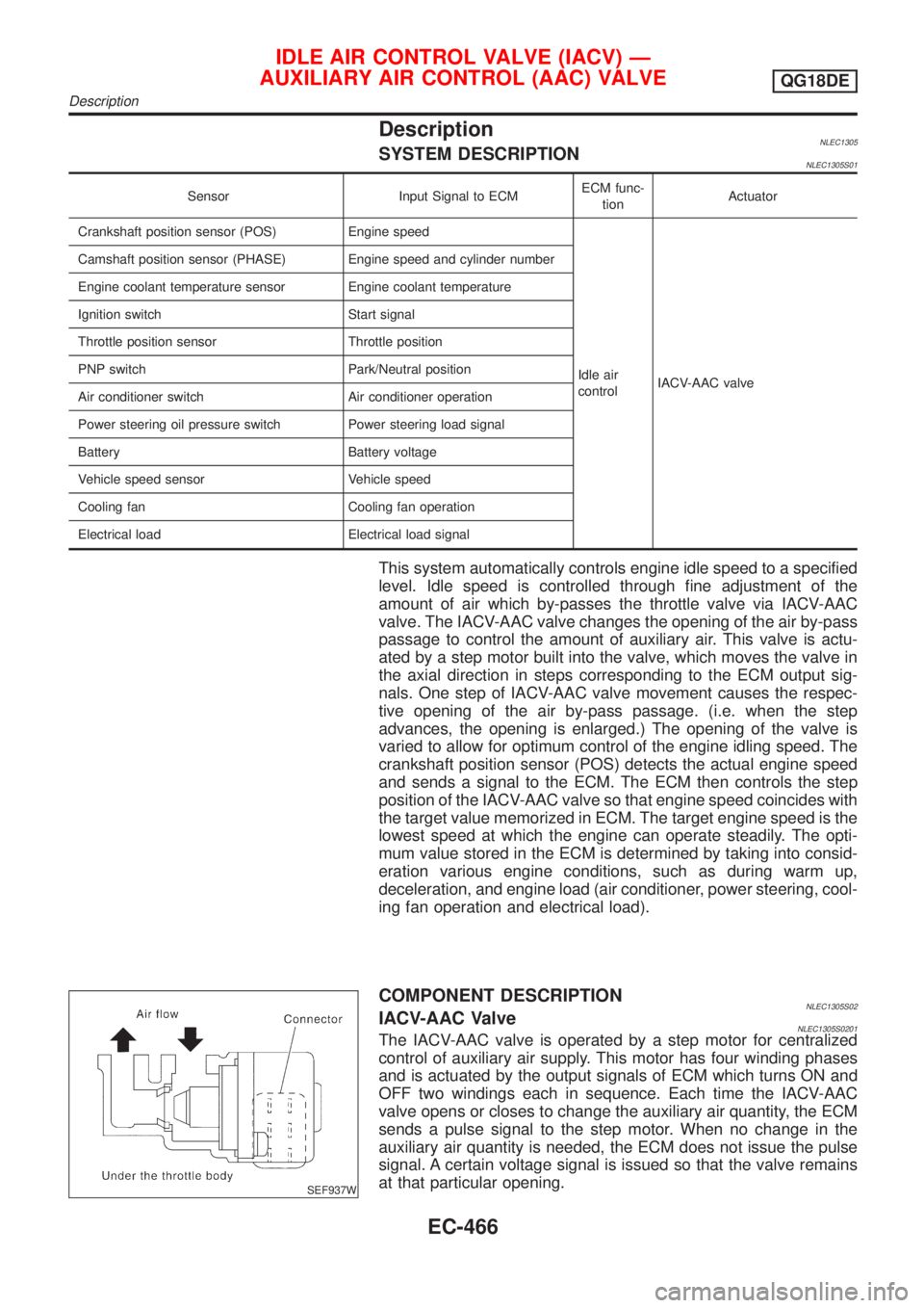
SEF937W
COMPONENT DESCRIPTIONNLEC1305S02IACV-AAC ValveNLEC1305S0201The IACV-AAC valve is operated by a step motor for centralized
control of auxiliary air supply. This motor has four winding phases
and is actuated by the output signals of ECM which turns ON and
OFF two windings each in sequence. Each time the IACV-AAC
valve opens or closes to change the auxiliary air quantity, the ECM
sends a pulse signal to the step motor. When no change in the
auxiliary air quantity is needed, the ECM does not issue the pulse
signal. A certain voltage signal is issued so that the valve remains
at that particular opening.
IDLE AIR CONTROL VALVE (IACV) Ð
AUXILIARY AIR CONTROL (AAC) VALVE
QG18DE
Description
EC-466
Page 1288 of 3051
DescriptionNLEC1768SYSTEM DESCRIPTIONNLEC1768S01
Sensor Input Signal to ECMECM func-
tionActuator
Camshaft position sensor Engine speed
Idle air
controlIACV-AAC valve Mass air flow sensor Amount of intake air
Engine coolant temperature sensor Engine coolant temperature
Ignition switch Start signal
Throttle position sensor Throttle position
Park/neutral position (PNP) switch Park/neutral position
Air conditioner switch Air conditioner operation
Power steering oil pressure switch Power steering load signal
Battery Battery voltage
Vehicle speed sensor Vehicle speed
Intake air temperature sensor Intake air temperature
Cooling fan Cooling fan operation
Electrical load Electrical load signal
This system automatically controls engine idle speed to a specified
level. Idle speed is controlled through fine adjustment of the
amount of air which by-passes the throttle valve via IACV-AAC
valve. The IACV-AAC valve changes the opening of the air by-pass
passage to control the amount of auxiliary air. This valve is actu-
ated by a step motor built into the valve, which moves the valve in
the axial direction in steps corresponding to the ECM output sig-
nals. One step of IACV-AAC valve movement causes the respec-
tive opening of the air by-pass passage. (i.e. when the step
advances, the opening is enlarged.) The opening of the valve is
varied to allow for optimum control of the engine idling speed. The
camshaft position sensor detects the actual engine speed and
sends a signal to the ECM. The ECM then controls the step posi-
tion of the IACV-AAC valve so that engine speed coincides with the
target value memorized in ECM. The target engine speed is the
lowest speed at which the engine can operate steadily. The opti-
mum value stored in the ECM is determined by takig into consid-
eration various engine conditions, such as during warm up,
deceleration, and engine load (air conditioner, power steering and
cooling fan operation).
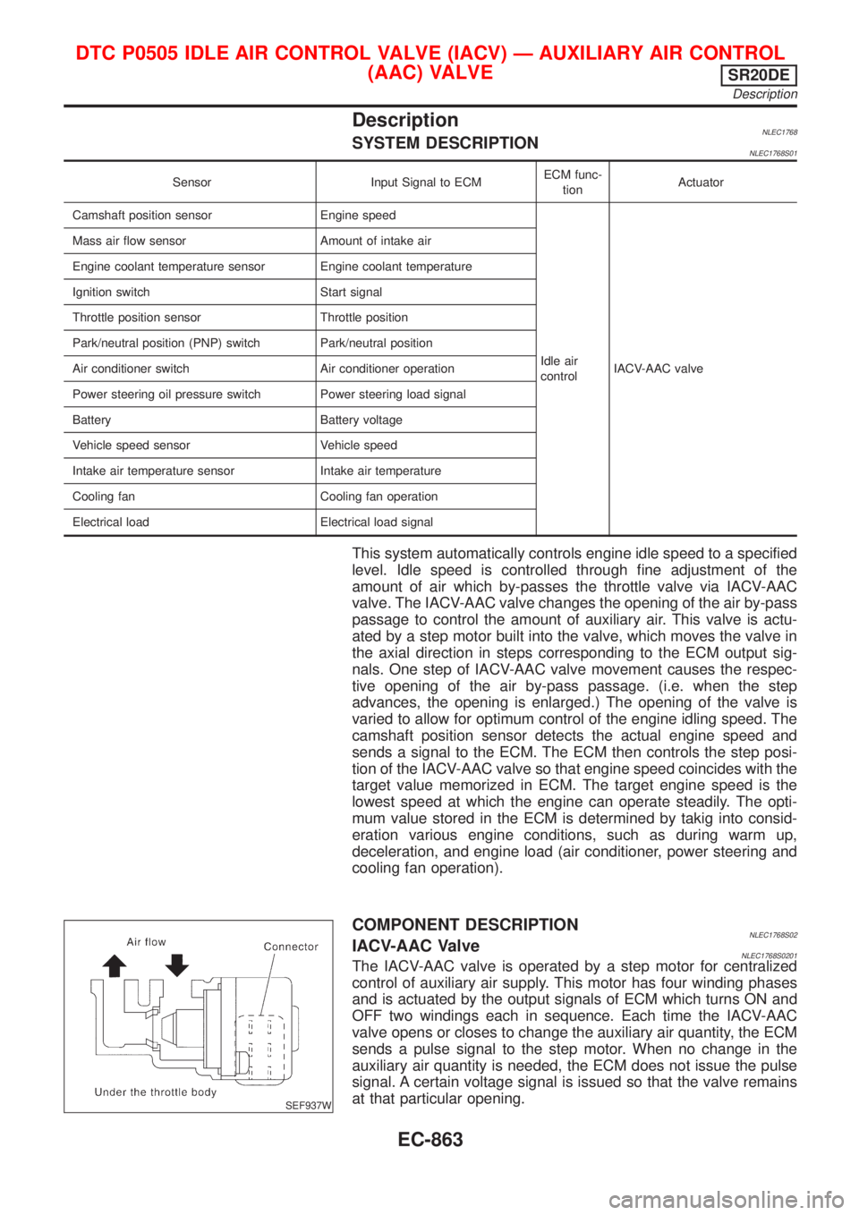
SEF937W
COMPONENT DESCRIPTIONNLEC1768S02IACV-AAC ValveNLEC1768S0201The IACV-AAC valve is operated by a step motor for centralized
control of auxiliary air supply. This motor has four winding phases
and is actuated by the output signals of ECM which turns ON and
OFF two windings each in sequence. Each time the IACV-AAC
valve opens or closes to change the auxiliary air quantity, the ECM
sends a pulse signal to the step motor. When no change in the
auxiliary air quantity is needed, the ECM does not issue the pulse
signal. A certain voltage signal is issued so that the valve remains
at that particular opening.
DTC P0505 IDLE AIR CONTROL VALVE (IACV) Ð AUXILIARY AIR CONTROL
(AAC) VALVE
SR20DE
Description
EC-863
Page 1420 of 3051
DescriptionNLEC1836SYSTEM DESCRIPTIONNLEC1836S01
Sensor Input Signal to ECMECM func-
tionActuator
Camshaft position sensor Engine speed
Idle air
controlIACV-AAC valve Mass air flow sensor Amount of intake air
Engine coolant temperature sensor Engine coolant temperature
Ignition switch Start signal
Throttle position sensor Throttle position
Park/neutral position (PNP) switch Park/neutral position
Air conditioner switch Air conditioner operation
Power steering oil pressure switch Power steering load signal
Battery Battery voltage
Vehicle speed sensor Vehicle speed
Intake air temperature sensor Intake air temperature
Cooling fan Cooling fan operation
Electrical load Electrical load signal
This system automatically controls engine idle speed to a specified
level. Idle speed is controlled through fine adjustment of the
amount of air which by-passes the throttle valve via IACV-AAC
valve. The IACV-AAC valve changes the opening of the air by-pass
passage to control the amount of auxiliary air. This valve is actu-
ated by a step motor built into the valve, which moves the valve in
the axial direction in steps corresponding to the ECM output sig-
nals. One step of IACV-AAC valve movement causes the respec-
tive opening of the air by-pass passage. (i.e. when the step
advances, the opening is enlarged.) The opening of the valve is
varied to allow for optimum control of the engine idling speed. The
camshaft position sensor detects the actual engine speed and
sends a signal to the ECM. The ECM then controls the step posi-
tion of the IACV-AAC valve so that engine speed coincides with the
target value memorized in ECM. The target engine speed is the
lowest speed at which the engine can operate steadily. The opti-
mum value stored in the ECM is determined by takig into consid-
eration various engine conditions, such as during warm up,
deceleration, and engine load (air conditioner, power steering and
cooling fan operation).
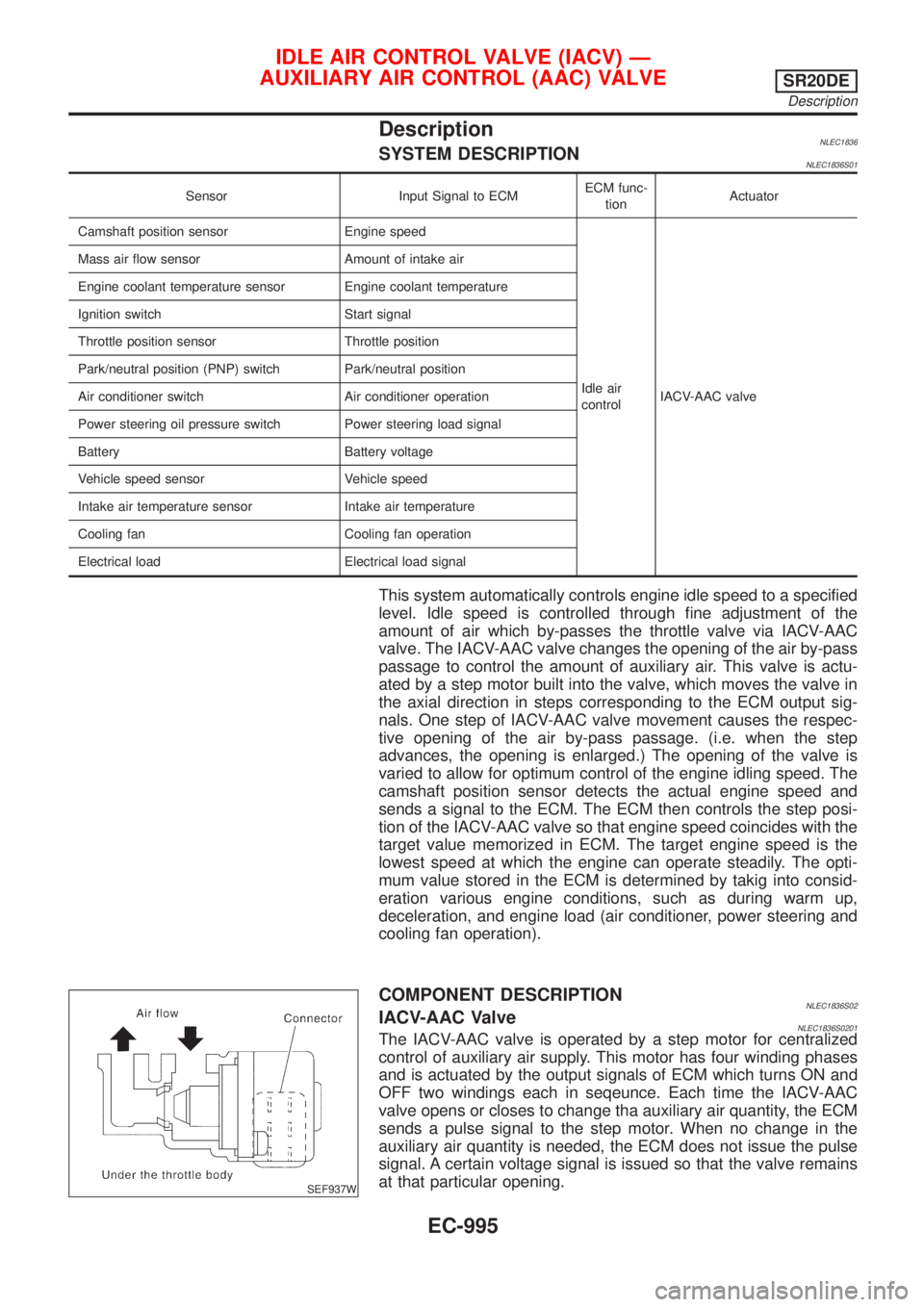
SEF937W
COMPONENT DESCRIPTIONNLEC1836S02IACV-AAC ValveNLEC1836S0201The IACV-AAC valve is operated by a step motor for centralized
control of auxiliary air supply. This motor has four winding phases
and is actuated by the output signals of ECM which turns ON and
OFF two windings each in seqeunce. Each time the IACV-AAC
valve opens or closes to change tha auxiliary air quantity, the ECM
sends a pulse signal to the step motor. When no change in the
auxiliary air quantity is needed, the ECM does not issue the pulse
signal. A certain voltage signal is issued so that the valve remains
at that particular opening.
IDLE AIR CONTROL VALVE (IACV) Ð
AUXILIARY AIR CONTROL (AAC) VALVE
SR20DE
Description
EC-995
Page 2476 of 3051
crankshaft position sensor (TDC sensor) from the assem-
bly.
+Always pay extra attention not to damage edge of crank-
shaft position sensor (TDC sensor) or ring gear teeth.
REMOVALNLEM0069S011. Remove engine undercover, and hood for hoisting.
2. Drain coolant from both cylinder block and radiator. Refer to
LC-59, ªChanging Engine Coolantº.
3. Remove the following parts:
+Battery
+RH and LH front wheels
+RH and LH splash covers (combined with undercover)
+Auxiliary belts
+Alternator
+Alternator brackets
+Radiator and cooling fan
+Engine cover
+Air ducts and air cleaner case
LH side of engine room:
4. Disconnect all harnesses and grounds that are connected to
components on vehicle.
5. Disconnect vacuum hose on vacuum pump side.
6. Disconnect fuel feed and fuel return hoses on engine side.
+Immediately put blind plugs into the openings to prevent
fuel from flowing out.
7. Disconnect heater hose. Plug opening of hose to prevent cool-
ant from flowing out.
RH side of engine room:
8. Remove air conditioner compressor from brackets and move
it toward vehicle side. Secure compressor on vehicle side with
rope.
Vehicle underside:
9. Remove exhaust front tube.
10. Disconnect two hoses from power steering pump and plug to
stop fluid.
11. Remove M/T control rod and support rod.
12. Remove ABS wheel sensor, and temporarily hang brake cali-
per with rope on vehicle side.
13. Remove RH and LH drive shafts.
SEM499G
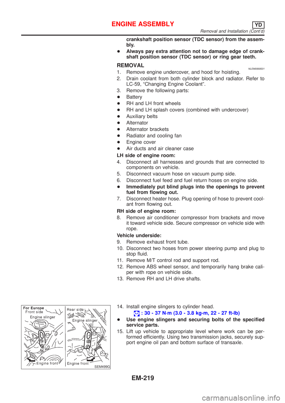
14. Install engine slingers to cylinder head.
: 30 - 37 N´m (3.0 - 3.8 kg-m, 22 - 27 ft-lb)
+Use engine slingers and securing bolts of the specified
service parts.
15. Lift up vehicle to appropriate level where work can be per-
formed efficiently. Using two transmission jacks, securely sup-
port engine oil pan and bottom surface of transaxle.
ENGINE ASSEMBLYYD
Removal and Installation (Cont'd)
EM-219
Page 2697 of 3051

A
A/C HFC134a (R134a) system precaution . HA-2
A/C HFC134a (R134a) system service
procedure .............................................. HA-85
A/C HFC134a (R134a) system service
tools ....................................................... HA-10
A/C HFC134a system service equip-
ment precaution ....................................... HA-6
A/C air flow ............................................... HA-19
A/C component layout .............................. HA-17
A/C compressor clutch removal and
installation .............................................. HA-90
A/C compressor precaution ........................ HA-5
A/C compressor special service tool .......... HA-9
A/C control linkage adjustment
(manual A/C) ......................................... HA-48
A/C control operation (manual A/C) .......... HA-18
A/C diagnostic work flow (manual
A/C) ...................................................... HA-40
A/C harness layout (manual A/C) ............. HA-21
A/C lubricant (R134a) ............................... HA-87
A/C operational check ............................... HA-41
A/C performance chart .............................. HA-78
A/C performance test diagnoses .............. HA-76
A/C relay ................................................... HA-73
A/C service data specification ................ HA-104
A/C switch ................................................. HA-74
A/C, M - Wiring diagram ........................... HA-27
A/CCUT - Wiring diagram ..................... EC-1301
A/T - Wiring diagram - AT - BA/FTS ........ AT-172
A/T - Wiring diagram - AT - ENG SS ........ AT-91,
177
A/T - Wiring diagram - AT - FTS ................ AT-75
A/T - Wiring diagram - AT - LPSV ... AT-101, 159
A/T - Wiring diagram - AT - MAIN ............. AT-62
A/T - Wiring diagram - AT - PNP/SW ........ AT-68
A/T - Wiring diagram - AT - SSV/A .......... AT-147
A/T - Wiring diagram - AT - TCV ....... AT-96, 166
A/T - Wiring diagram - AT - TPS ..... AT-106, 139
A/T - Wiring diagram - AT - VSS/AT .. AT-86, 128
A/T - Wiring diagram - AT -
VSSMTR .............................................. AT-134
A/T control ............................................. EC-1012
A/T diagnosis communication line .......... EC-928
A/T shift lock system - Wiring
diagram ................................................ AT-196
A/T shift lock system ................................ AT-195
A/T trouble diagnoses .......................... AT-41, 46
AAC/V - Wiring diagram . EC-345, 468, 865, 997
ABS (anti-lock brake system) ................... BR-42
ABS - Wiring diagram ............................... BR-48
ABS sensor rotor ....................................... AX-23
APS - Wiring diagram ........................... EC-1155
AT/C - Wiring diagram .......................... EC-1013
ATDIAG - Wiring diagram ....................... EC-929
Accelerator control system .................... FE-3, 14
Accelerator position sensor ................... EC-1155
Air bag disposal ........................................ RS-30Air bag precautions .................................. GI-3
Air bag ....................................................... RS-16
Air bleeding (hydraulic clutch) ................... CL-10
Air bleeding for brake system ..................... BR-8
Air conditioner cut control ....... EC-38, 572, 1081
Air flow meter - See Mass air flow
sensor ................................ EC-154, 679, 1143
Air mix door control linkage
adjustment ............................................. HA-50
Air spoiler, rear .......................................... BT-38
Alternator ................................................... SC-28
Angular tightening application ...... EM-5, 76, 158
Antenna - See Power antenna ................ EL-233
Anti-lock brake system - Wiring
diagram .................................................. BR-48
Audio and A/C control removal and
installation - See Instrument panel ........ BT-22
Audio ........................................................ EL-208
Automatic transaxle number ...................... GI-40
Auxiliary air control (AAC) valve .... EC-343, 466,
863, 995
B
Back-up lamp switch (M/T) ....................... MT-16
Back-up lamp ............................................. EL-93
Ball joint (front) .......................................... SU-13
Basic inspection ...................... EC-99, 623,1111
Battery ......................................................... SC-3
Baulk ring (M/T) .................................. MT-25, 63
Blower motor ............................................. HA-61
Blower resistor .......................................... HA-61
Board-on lift ................................................ GI-42
Body alignment .......................................... BT-65
Brake booster ............................................ BR-16
Brake fluid change ...................................... BR-7
Brake fluid level and line check .................. BR-7
Brake hydraulic line .................................... BR-9
Brake pedal ............................................... BR-11
Bulb specifications ................................... EL-524
Bumper, front .............................................. BT-7
Bumper, rear .............................................. BT-10
C
CHARGE - Wiring diagram ....................... SC-25
CHIME - Wiring diagram ......................... EL-166
CIGAR - Wiring diagram ......................... EL-195
CKPS - Wiring diagram . EC-297, 440, 821, 911,
970, 1166
CMPS - Wiring diagram .................. EC-304, 828
CONSULT for ABS .................................... BR-58
CONSULT for engine .............. EC-82, 607, 1102
COOL/F - Wiring diagram ..... EC-376, 885, 1201
Camshaft inspection ................. EM-36, 114, 204
Camshaft position sensor (CMPS) . EC-302, 825
Camshaft position sensor (PHASE) ........ EC-302
ALPHABETICAL INDEX
IDX-2