Page 187 of 3051
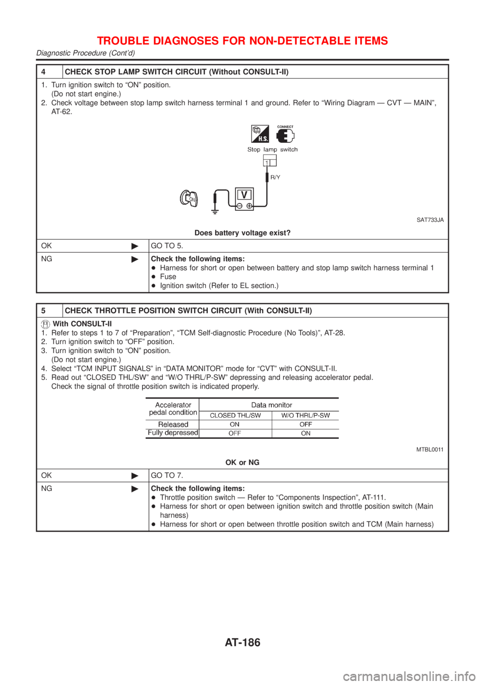
4 CHECK STOP LAMP SWITCH CIRCUIT (Without CONSULT-II)
1. Turn ignition switch to ªONº position.
(Do not start engine.)
2. Check voltage between stop lamp switch harness terminal 1 and ground. Refer to ªWiring Diagram Ð CVT Ð MAINº,
AT-62.
SAT733JA
Does battery voltage exist?
OK©GO TO 5.
NG©Check the following items:
+Harness for short or open between battery and stop lamp switch harness terminal 1
+Fuse
+Ignition switch (Refer to EL section.)
5 CHECK THROTTLE POSITION SWITCH CIRCUIT (With CONSULT-II)
With CONSULT-II
1. Refer to steps 1 to 7 of ªPreparationº, ªTCM Self-diagnostic Procedure (No Tools)º, AT-28.
2. Turn ignition switch to ªOFFº position.
3. Turn ignition switch to ªONº position.
(Do not start engine.)
4. Select ªTCM INPUT SIGNALSº in ªDATA MONITORº mode for ªCVTº with CONSULT-II.
5. Read out ªCLOSED THL/SWº and ªW/O THRL/P-SWº depressing and releasing accelerator pedal.
Check the signal of throttle position switch is indicated properly.
MTBL0011
OK or NG
OK©GO TO 7.
NG©Check the following items:
+Throttle position switch Ð Refer to ªComponents Inspectionº, AT-111.
+Harness for short or open between ignition switch and throttle position switch (Main
harness)
+Harness for short or open between throttle position switch and TCM (Main harness)
TROUBLE DIAGNOSES FOR NON-DETECTABLE ITEMS
Diagnostic Procedure (Cont'd)
AT-186
Page 193 of 3051
SAT261K
SPORT Indicator Lamp Does Not Come On=NLAT0295SYMPTOM:
SPORT indicator lamp does not come on for about 2 seconds
when turning ignition switch to ªONº.
1 CHECK TCM POWER SOURCE
SAT262K
1. Turn ignition switch to ªOFFº position.
2. Check voltage between TCM terminal 28 and ground.
Voltage: Battery voltage
OK or NG
OK©GO TO 2.
NG©Check the following items:
+Harness for short or open between battery terminal and TCM terminal 28 (Main har-
ness).
+Refer to ªWiring Diagram Ð AT Ð MAINº, AT-62.
+Ignition switch and fuse Refer to EL section, ªPOWER SUPPLY ROUTINGº.
TROUBLE DIAGNOSES FOR SYMPTOMS
SPORT Indicator Lamp Does Not Come On
AT-192
Page 194 of 3051
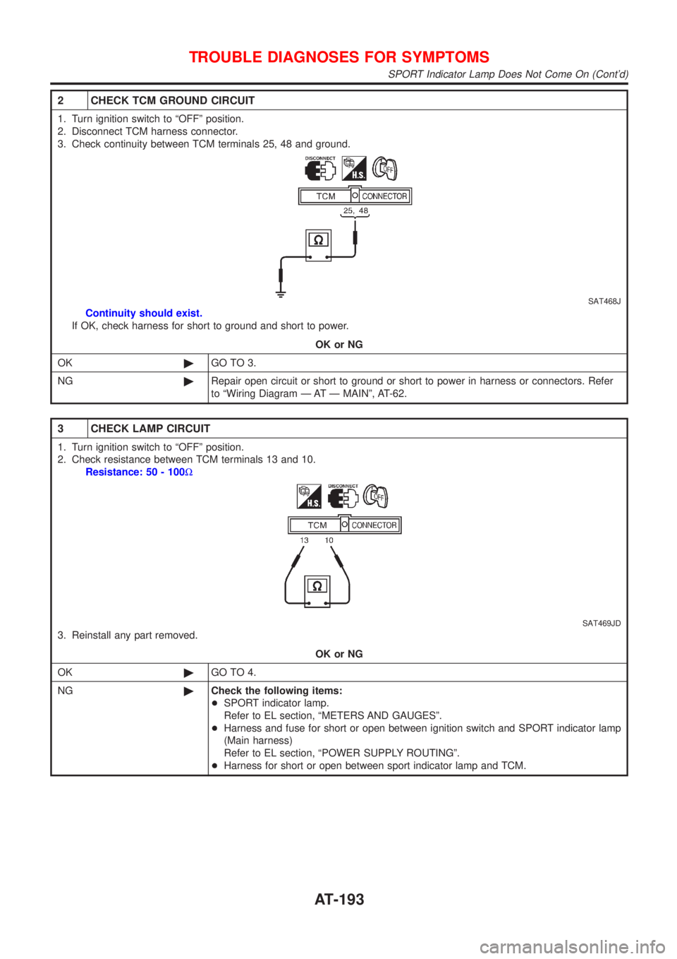
2 CHECK TCM GROUND CIRCUIT
1. Turn ignition switch to ªOFFº position.
2. Disconnect TCM harness connector.
3. Check continuity between TCM terminals 25, 48 and ground.
SAT468J
Continuity should exist.
If OK, check harness for short to ground and short to power.
OK or NG
OK©GO TO 3.
NG©Repair open circuit or short to ground or short to power in harness or connectors. Refer
to ªWiring Diagram Ð AT Ð MAINº, AT-62.
3 CHECK LAMP CIRCUIT
1. Turn ignition switch to ªOFFº position.
2. Check resistance between TCM terminals 13 and 10.
Resistance: 50 - 100W
SAT469JD
3. Reinstall any part removed.
OK or NG
OK©GO TO 4.
NG©Check the following items:
+SPORT indicator lamp.
Refer to EL section, ªMETERS AND GAUGESº.
+Harness and fuse for short or open between ignition switch and SPORT indicator lamp
(Main harness)
Refer to EL section, ªPOWER SUPPLY ROUTINGº.
+Harness for short or open between sport indicator lamp and TCM.
TROUBLE DIAGNOSES FOR SYMPTOMS
SPORT Indicator Lamp Does Not Come On (Cont'd)
AT-193
Page 574 of 3051
2 CHECK ECM POWER SUPPLY CIRCUIT-I
1. Turn ignition switch ªOFFº and then ªONº.
2. Check voltage between ECM terminal 43 and ground with CONSULT-II or tester.
SEF291X
OK or NG
OK©GO TO 4.
NG©GO TO 3.
3 DETECT MALFUNCTIONING PART
Check the following.
+Harness connectors M50, F44 (where fitted)
+Harness connectors M72, F44 (where fitted)
+Fuse block (J/B) connector M1, E108
+10A fuse
+Harness for open or short between ECM and ignition switch
©Repair harness or connectors.
4 CHECK ECM GROUND CIRCUIT FOR OPEN AND SHORT-I
1. Turn ignition switch ªOFFº.
2. Disconnect ECM harness connector.
3. Check harness continuity between ECM terminals 48, 57, 106, 108 and engine ground.
Refer to WIRING DIAGRAM.
Continuity should exist.
4. Also check harness for short to power.
OK or NG
OK©GO TO 5.
NG©Repair open circuit or short to power in harness or connectors.
TROUBLE DIAGNOSIS FOR POWER SUPPLYQG18DE
Main Power Supply and Ground Circuit (Cont'd)
EC-149
Page 577 of 3051
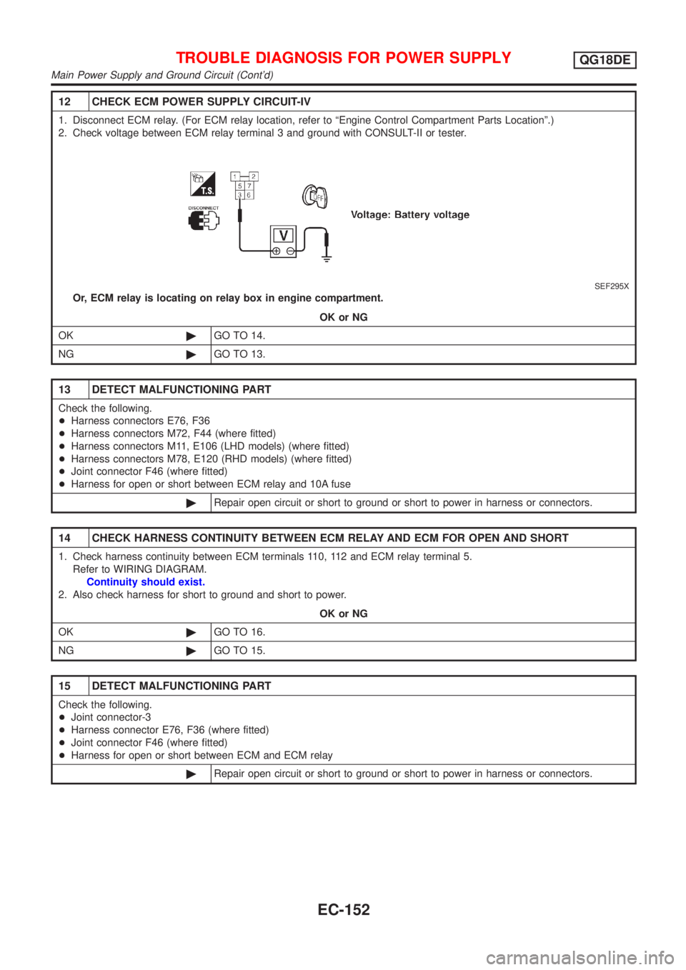
12 CHECK ECM POWER SUPPLY CIRCUIT-IV
1. Disconnect ECM relay. (For ECM relay location, refer to ªEngine Control Compartment Parts Locationº.)
2. Check voltage between ECM relay terminal 3 and ground with CONSULT-II or tester.
SEF295X
Or, ECM relay is locating on relay box in engine compartment.
OK or NG
OK©GO TO 14.
NG©GO TO 13.
13 DETECT MALFUNCTIONING PART
Check the following.
+Harness connectors E76, F36
+Harness connectors M72, F44 (where fitted)
+Harness connectors M11, E106 (LHD models) (where fitted)
+Harness connectors M78, E120 (RHD models) (where fitted)
+Joint connector F46 (where fitted)
+Harness for open or short between ECM relay and 10A fuse
©Repair open circuit or short to ground or short to power in harness or connectors.
14 CHECK HARNESS CONTINUITY BETWEEN ECM RELAY AND ECM FOR OPEN AND SHORT
1. Check harness continuity between ECM terminals 110, 112 and ECM relay terminal 5.
Refer to WIRING DIAGRAM.
Continuity should exist.
2. Also check harness for short to ground and short to power.
OK or NG
OK©GO TO 16.
NG©GO TO 15.
15 DETECT MALFUNCTIONING PART
Check the following.
+Joint connector-3
+Harness connector E76, F36 (where fitted)
+Joint connector F46 (where fitted)
+Harness for open or short between ECM and ECM relay
©Repair open circuit or short to ground or short to power in harness or connectors.
TROUBLE DIAGNOSIS FOR POWER SUPPLYQG18DE
Main Power Supply and Ground Circuit (Cont'd)
EC-152
Page 650 of 3051
Diagnostic ProcedureNLEC0142
1 CHECK POWER SUPPLY
1. Turn ignition switch ªOFFº.
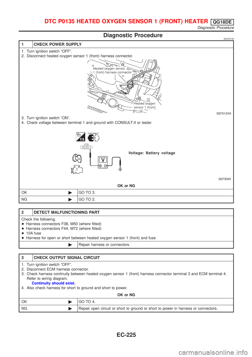
2. Disconnect heated oxygen sensor 1 (front) harness connector.
SEF012XA
3. Turn ignition switch ªONº.
4. Check voltage between terminal 1 and ground with CONSULT-II or tester.
SEF934X
OK or NG
OK©GO TO 3.
NG©GO TO 2.
2 DETECT MALFUNCTIONING PART
Check the following.
+Harness connectors F38, M50 (where fitted)
+Harness connectors F44, M72 (where fitted)
+10A fuse
+Harness for open or short between heated oxygen sensor 1 (front) and fuse
©Repair harness or connectors.
3 CHECK OUTPUT SIGNAL CIRCUIT
1. Turn ignition switch ªOFFº.
2. Disconnect ECM harness connector.
3. Check harness continuity between heated oxygen sensor 1 (front) harness connector terminal 3 and ECM terminal 4.
Refer to wiring diagram.
Continuity should exist.
4. Also check harness for short to ground and short to power.
OK or NG
OK©GO TO 4.
NG©Repair open circuit or short to ground or short to power in harness or connectors.
DTC P0135 HEATED OXYGEN SENSOR 1 (FRONT) HEATERQG18DE
Diagnostic Procedure
EC-225
Page 692 of 3051
Diagnostic ProcedureNLEC0186
1 CHECK POWER SUPPLY
1. Turn ignition switch ªOFFº.
2. Disconnect heated oxygen sensor 2 (rear) harness connector.
SEF639Z
3. Turn ignition switch ªONº.
4. Check voltage between terminal 2 and ground.
SEF218W
OK or NG
OK©GO TO 3.
NG©GO TO 2.
2 DETECT MALFUNCTIONING PART
Check the following.
+Harness connectors F38, M50 (where fitted)
+Harness connectors F44, M72 (where fitted)
+Harness for open or short between heated oxygen sensor 2 (rear) and fuse
+10A fuse
©Repair harness or connectors.
3 CHECK OUTPUT SIGNAL CIRCUIT
1. Turn ignition switch ªOFFº.
2. Disconnect ECM harness connector.
3. Check harness continuity between heated oxygen sensor 2 (rear) harness connector terminal 3 and ECM terminal 3.
Refer to wiring diagram.
Continuity should exist.
4. Also check harness for short to ground and short to power.
OK or NG
OK©GO TO 5.
NG©GO TO 4.
DTC P0141 HEATED OXYGEN SENSOR 2 HEATER (REAR)QG18DE
Diagnostic Procedure
EC-267
Page 749 of 3051
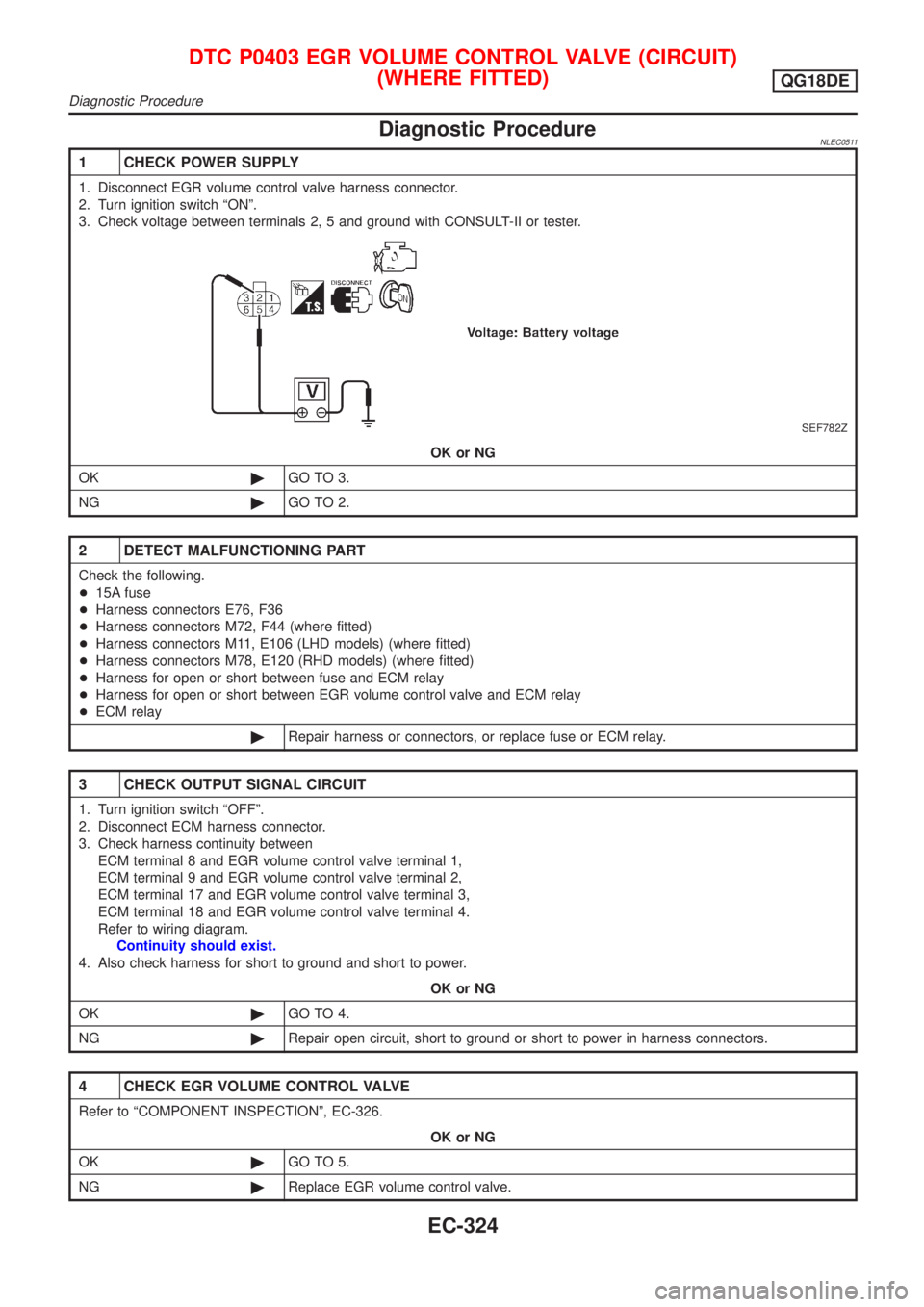
Diagnostic ProcedureNLEC0511
1 CHECK POWER SUPPLY
1. Disconnect EGR volume control valve harness connector.
2. Turn ignition switch ªONº.
3. Check voltage between terminals 2, 5 and ground with CONSULT-II or tester.
SEF782Z
OK or NG
OK©GO TO 3.
NG©GO TO 2.
2 DETECT MALFUNCTIONING PART
Check the following.
+15A fuse
+Harness connectors E76, F36
+Harness connectors M72, F44 (where fitted)
+Harness connectors M11, E106 (LHD models) (where fitted)
+Harness connectors M78, E120 (RHD models) (where fitted)
+Harness for open or short between fuse and ECM relay
+Harness for open or short between EGR volume control valve and ECM relay
+ECM relay
©Repair harness or connectors, or replace fuse or ECM relay.
3 CHECK OUTPUT SIGNAL CIRCUIT
1. Turn ignition switch ªOFFº.
2. Disconnect ECM harness connector.
3. Check harness continuity between
ECM terminal 8 and EGR volume control valve terminal 1,
ECM terminal 9 and EGR volume control valve terminal 2,
ECM terminal 17 and EGR volume control valve terminal 3,
ECM terminal 18 and EGR volume control valve terminal 4.
Refer to wiring diagram.
Continuity should exist.
4. Also check harness for short to ground and short to power.
OK or NG
OK©GO TO 4.
NG©Repair open circuit, short to ground or short to power in harness connectors.
4 CHECK EGR VOLUME CONTROL VALVE
Refer to ªCOMPONENT INSPECTIONº, EC-326.
OK or NG
OK©GO TO 5.
NG©Replace EGR volume control valve.
DTC P0403 EGR VOLUME CONTROL VALVE (CIRCUIT)
(WHERE FITTED)
QG18DE
Diagnostic Procedure
EC-324