Page 52 of 3051

SAT767B
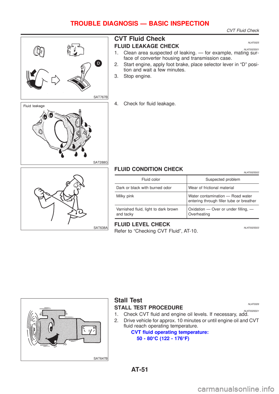
CVT Fluid CheckNLAT0025FLUID LEAKAGE CHECKNLAT0025S011. Clean area suspected of leaking. Ð for example, mating sur-
face of converter housing and transmission case.
2. Start engine, apply foot brake, place selector lever in ªDº posi-
tion and wait a few minutes.
3. Stop engine.
SAT288G
4. Check for fluid leakage.
SAT638A
FLUID CONDITION CHECKNLAT0025S02
Fluid color Suspected problem
Dark or black with burned odor Wear of frictional material
Milky pink Water contamination Ð Road water
entering through filler tube or breather
Varnished fluid, light to dark brown
and tackyOxidation Ð Over or under filling, Ð
Overheating
FLUID LEVEL CHECKNLAT0025S03Refer to ªChecking CVT Fluidº, AT-10.
SAT647B
Stall TestNLAT0026STALL TEST PROCEDURENLAT0026S011. Check CVT fluid and engine oil levels. If necessary, add.
2. Drive vehicle for approx. 10 minutes or until engine oil and CVT
fluid reach operating temperature.
CVT fluid operating temperature:
50 - 80ÉC (122 - 176ÉF)
TROUBLE DIAGNOSIS Ð BASIC INSPECTION
CVT Fluid Check
AT-51
Page 208 of 3051

SAT266K
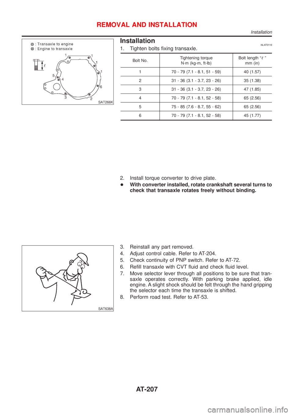
InstallationNLAT01161. Tighten bolts fixing transaxle.
Bolt No.Tightening torque
N´m (kg-m, ft-lb)Bolt length ª!º
mm (in)
1 70 - 79 (7.1 - 8.1, 51 - 59) 40 (1.57)
2 31 - 36 (3.1 - 3.7, 23 - 26) 35 (1.38)
3 31 - 36 (3.1 - 3.7, 23 - 26) 47 (1.85)
4 70 - 79 (7.1 - 8.1, 52 - 58) 65 (2.56)
5 75 - 85 (7.6 - 8.7, 55 - 62) 65 (2.56)
6 70 - 79 (7.1 - 8.1, 52 - 58) 45 (1.77)
2. Install torque converter to drive plate.
+With converter installed, rotate crankshaft several turns to
check that transaxle rotates freely without binding.
SAT638A
3. Reinstall any part removed.
4. Adjust control cable. Refer to AT-204.
5. Check continuity of PNP switch. Refer to AT-72.
6. Refill transaxle with CVT fluid and check fluid level.
7. Move selector lever through all positions to be sure that tran-
saxle operates correctly. With parking brake applied, idle
engine. A slight shock should be felt through the hand gripping
the selector each time the transaxle is shifted.
8. Perform road test. Refer to AT-53.
REMOVAL AND INSTALLATION
Installation
AT-207
Page 217 of 3051
SFA898A
2. Remove brake caliper assembly and rotor.
Brake hose need not be disconnected from brake caliper. In
this case, suspend caliper assembly with wire so as not to
stretch brake hose. Be careful not to depress brake pedal, or
piston will pop out.
Make sure brake hose is not twisted.
SFA372-A
3. Separate tie-rod from knuckle with Tool.
Install stud nut on stud bolt to prevent damage to stud bolt.
SFA181A
4. Separate drive shaft from knuckle by lightly tapping it. If it is
hard to remove, use a puller.
Cover boots with shop towel so as not to damage them when
removing drive shaft.
SFA153B
5. Remove strut lower mounting bolts.
SFA113AC
6. Loosen lower ball joint tightening nut.
7. Separate knuckle from lower ball joint stud with Tool.
8. Remove knuckle from transverse link.
FRONT AXLE
Wheel Hub and Knuckle (Cont’d)
AX-6
Page 222 of 3051
SFA090A
REMOVALNLAX00141. Remove wheel bearing lock nut.
Brake caliper need not be disconnected. Do not twist or
stretch brake hose when moving components.
SFA153B
2. Remove strut lower mount bolts.
3. Remove brake hose clip.
SFA499A
4. Separate drive shaft from knuckle by lightly tapping it. If it is
hard to remove, use a puller.
Cover boots with shop towel so as not to damage them
when removing drive shaft.
Refer to“Wheel Hub and Knuckle”,“FRONT AXLE”, AX-5.
5. Remove right drive shaft from transaxle.
NAX004
6. Remove left drive shaft from transaxle.
+Pry off drive shaft from transaxle as shown at left.
SFA482-D
INSTALLATIONNLAX0015Transaxle SideNLAX0015S011. Drive a new oil seal to transaxle. Refer to MT-15 or AT-204,
“Replacing Oil Seal”or“Differential Side Oil Seal
Replacement”,“ON-VEHICLE SERVICE”.
2. Set Tool along the inner circumference of oil seal.
FRONT AXLE
Drive Shaft (Cont’d)
AX-11
Page 252 of 3051

InstallationNLBR0121CAUTION:
+Refill with new brake fluid“DOT 4”.
+Never reuse drained brake fluid.
1. Place master cylinder onto brake booster and secure mount-
ing nuts lightly.
2. Torque mounting nuts.
:13-15N·m (1.3 - 1.5 kg-m,9-11ft-lb)
NBR363
NBR364
3. Check hoses for damage. If the hoses show cracks or damage,
replace the hose.
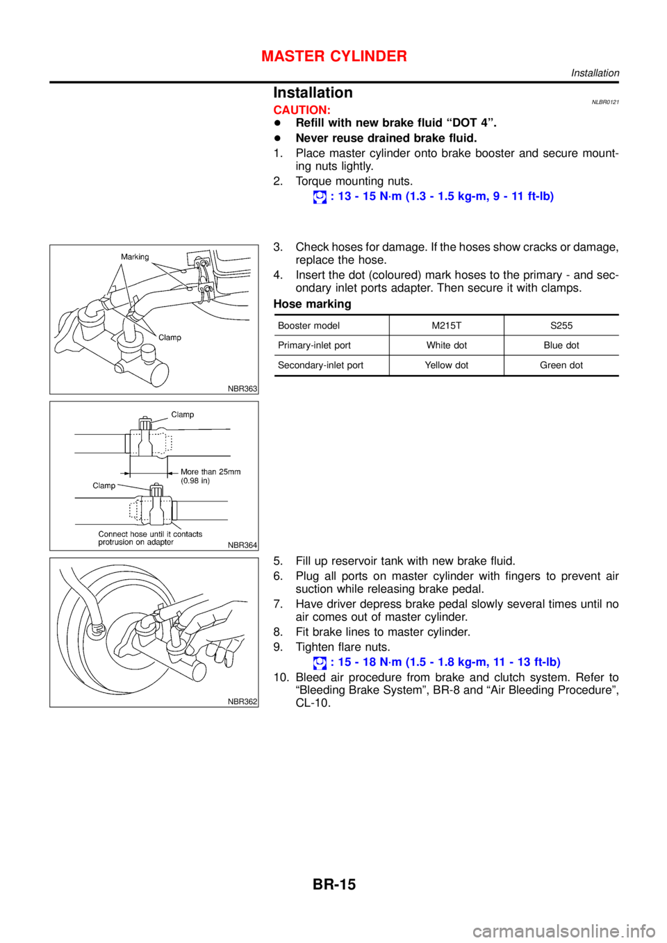
4. Insert the dot (coloured) mark hoses to the primary - and sec-
ondary inlet ports adapter. Then secure it with clamps.
Hose marking
Booster model M215T S255
Primary-inlet port White dot Blue dot
Secondary-inlet port Yellow dot Green dot
NBR362
5. Fill up reservoir tank with new brake fluid.
6. Plug all ports on master cylinder with fingers to prevent air
suction while releasing brake pedal.
7. Have driver depress brake pedal slowly several times until no
air comes out of master cylinder.
8. Fit brake lines to master cylinder.
9. Tighten flare nuts.
:15-18N·m (1.5 - 1.8 kg-m, 11 - 13 ft-lb)
10. Bleed air procedure from brake and clutch system. Refer to
“Bleeding Brake System”, BR-8 and“Air Bleeding Procedure”,
CL-10.
MASTER CYLINDER
Installation
BR-15
Page 253 of 3051

SBR002A
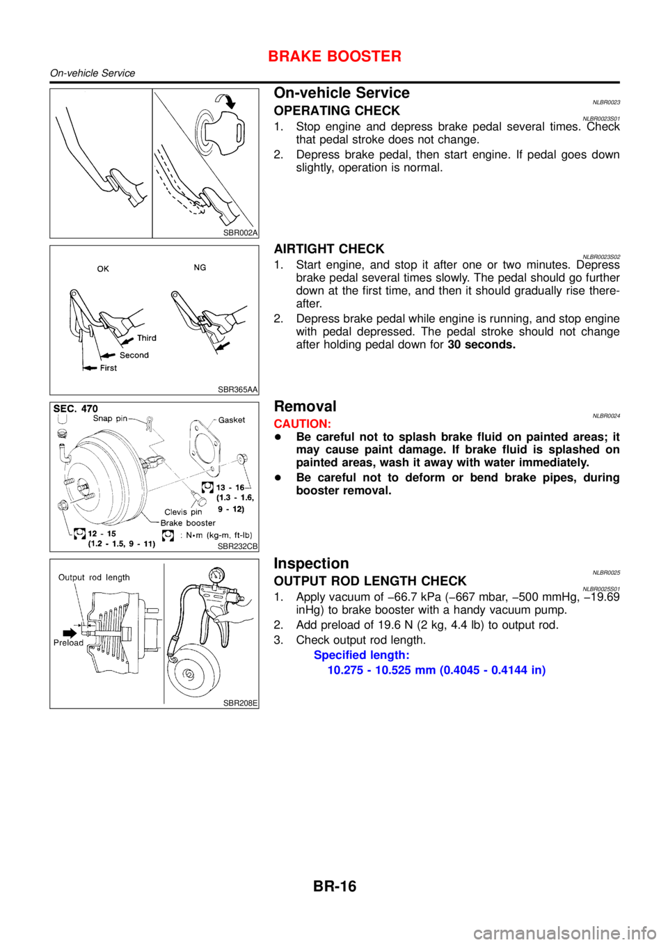
On-vehicle ServiceNLBR0023OPERATING CHECKNLBR0023S011. Stop engine and depress brake pedal several times. Check
that pedal stroke does not change.
2. Depress brake pedal, then start engine. If pedal goes down
slightly, operation is normal.
SBR365AA
AIRTIGHT CHECKNLBR0023S021. Start engine, and stop it after one or two minutes. Depress
brake pedal several times slowly. The pedal should go further
down at the first time, and then it should gradually rise there-
after.
2. Depress brake pedal while engine is running, and stop engine
with pedal depressed. The pedal stroke should not change
after holding pedal down for30 seconds.
SBR232CB
RemovalNLBR0024CAUTION:
+Be careful not to splash brake fluid on painted areas; it
may cause paint damage. If brake fluid is splashed on
painted areas, wash it away with water immediately.
+Be careful not to deform or bend brake pipes, during
booster removal.
SBR208E
InspectionNLBR0025OUTPUT ROD LENGTH CHECKNLBR0025S011. Apply vacuum of �66.7 kPa (�667 mbar, �500 mmHg, �19.69
inHg) to brake booster with a handy vacuum pump.
2. Add preload of 19.6 N (2 kg, 4.4 lb) to output rod.
3. Check output rod length.
Specified length:
10.275 - 10.525 mm (0.4045 - 0.4144 in)
BRAKE BOOSTER
On-vehicle Service
BR-16
Page 254 of 3051
InstallationNLBR0026CAUTION:
+Be careful not to deform or bend brake pipes, during
booster installation.
+Replace clevis pin if damaged.
+Refill with new brake fluid“DOT 4”.
+Never reuse drained brake fluid.
+Take care not to damage brake booster mounting bolt
thread during installation. Due to the acute angle of
installation, the threads can be damaged with the dash
panel.
SBR237EA
1. Before fitting booster, temporarily adjust clevis to dimension
shown.
2. Fit booster, then secure mounting nuts (brake pedal bracket to
master cylinder) lightly.
3. Connect brake pedal and booster input rod with clevis pin.
4. Secure mounting nuts.
Specification:
13-16N·m (1.3 - 1.6 kg-m,9-12ft-lb)
5. Install master cylinder. Refer to“Installation”in“MASTER
CYLINDER”, BR-15.
6. Bleed air. Refer to“Bleeding Brake System”, BR-8 and“Air
Bleeding Procedure”, CL-10.
BRAKE BOOSTER
Installation
BR-17
Page 280 of 3051

System ComponentsNLBR0086
NBR369
SBR124B
System DescriptionNLBR0087SENSORNLBR0087S01The sensor unit consists of a gear-shaped sensor rotor and a sen-
sor element. The element contains a bar magnet around which a
coil is wound. The sensor is installed on the back side of the brake
rotor. Sine-wave current is generated by the sensor as the wheel
rotates. The frequency and voltage increase(s) as the rotating
speed increases.
SBR759E
CONTROL UNITNLBR0087S02The control unit computes the wheel rotating speed by the signal
current sent from the sensor. Then it supplies a DC current to the
actuator solenoid valve. It also controls ON-OFF operation of the
valve relay and motor relay. If any electrical malfunction should be
detected in the system, the control unit causes the warning lamp
to light up. In this condition, the ABS will be deactivated by the
control unit, and the vehicle’s brake system reverts to normal
operation.
SBR176E
ABS ACTUATOR AND ELECTRIC UNITNLBR0087S03The ABS actuator and electric unit contains:
+An electric motor and pump
+Two relays
+Eight solenoid valves, each inlet and outlet for
—LH front
—RH front
—LH rear
—RH rear
+ABS control unit
DESCRIPTIONABS
System Components
BR-43