2001 NISSAN ALMERA TINO coolant temperature
[x] Cancel search: coolant temperaturePage 20 of 3051
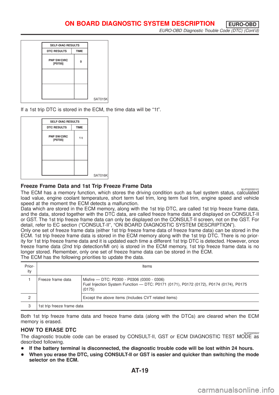
SAT015K
If a 1st trip DTC is stored in the ECM, the time data will be ª1tº.
SAT016K
Freeze Frame Data and 1st Trip Freeze Frame DataNLAT0020S0101The ECM has a memory function, which stores the driving condition such as fuel system status, calculated
load value, engine coolant temperature, short term fuel trim, long term fuel trim, engine speed and vehicle
speed at the moment the ECM detects a malfunction.
Data which are stored in the ECM memory, along with the 1st trip DTC, are called 1st trip freeze frame data,
and the data, stored together with the DTC data, are called freeze frame data and displayed on CONSULT-II
or GST. The 1st trip freeze frame data can only be displayed on the CONSULT-II screen, not on the GST. For
detail, refer to EC section (ªCONSULT-IIº, ªON BOARD DIAGNOSTIC SYSTEM DESCRIPTIONº).
Only one set of freeze frame data (either 1st trip freeze frame data of freeze frame data) can be stored in the
ECM. 1st trip freeze frame data is stored in the ECM memory along with the 1st trip DTC. There is no prior-
ity for 1st trip freeze frame data and it is updated each time a different 1st trip DTC is detected. However, once
freeze frame data (2nd trip detection/MI on) is stored in the ECM memory, 1st trip freeze frame data is no
longer stored. Remember, only one set of freeze frame data can be stored in the ECM.
The ECM has the following priorities to update the data.
Prior-
ityItems
1 Freeze frame data Misfire Ð DTC: P0300 - P0306 (0300 - 0306)
Fuel Injection System Function Ð DTC: P0171 (0171), P0172 (0172), P0174 (0174), P0175
(0175)
2 Except the above items (Includes CVT related items)
3 1st trip freeze frame data
Both 1st trip freeze frame data and freeze frame data (along with the DTCs) are cleared when the ECM
memory is erased.
HOW TO ERASE DTCNLAT0020S02The diagnostic trouble code can be erased by CONSULT-II, GST or ECM DIAGNOSTIC TEST MODE as
described following.
+If the battery terminal is disconnected, the diagnostic trouble code will be lost within 24 hours.
+When you erase the DTC, using CONSULT-II or GST is easier and quicker than switching the mode
selector on the ECM.
ON BOARD DIAGNOSTIC SYSTEM DESCRIPTIONEURO-OBD
EURO-OBD Diagnostic Trouble Code (DTC) (Cont'd)
AT-19
Page 427 of 3051
DTC P0100 MASS AIR FLOW SENSOR (MAFS)......154
Component Description ...........................................154
CONSULT-II Reference Value in Data Monitor
Mode ........................................................................154
ECM Terminals and Reference Value .....................154
On Board Diagnosis Logic.......................................154
Fail-safe Mode .........................................................155
DTC Confirmation Procedure ..................................155
Wiring Diagram ........................................................156
Diagnostic Procedure ..............................................158
Component Inspection .............................................160
DTC P0110 INTAKE AIR TEMPERATURE
SENSOR......................................................................161
Component Description ...........................................161
On Board Diagnosis Logic.......................................162
DTC Confirmation Procedure ..................................162
Wiring Diagram ........................................................163
Diagnostic Procedure ..............................................165
Component Inspection .............................................167
DTC P0115 ENGINE COOLANT TEMPERATURE
SENSOR (ECTS) (CIRCUIT).......................................169
Component Description ...........................................169
CONSULT-II Reference Value in Data Monitor
Mode ........................................................................169
On Board Diagnosis Logic.......................................169
Fail-safe Mode .........................................................170
DTC Confirmation Procedure ..................................170
Wiring Diagram ........................................................171
Diagnostic Procedure ..............................................173
Component Inspection .............................................174
DTC P0120 THROTTLE POSITION SENSOR...........175
Component Description ...........................................175
CONSULT-II Reference Value in Data Monitor
Mode ........................................................................175
ECM Terminals and Reference Value .....................176
On Board Diagnosis Logic.......................................176
Fail-safe Mode .........................................................176
DTC Confirmation Procedure ..................................176
Wiring Diagram ........................................................178
Diagnostic Procedure ..............................................180
Component Inspection .............................................182
DTC P0130 HEATED OXYGEN SENSOR 1
(FRONT) (CIRCUIT).....................................................184
Component Description ...........................................184
CONSULT-II Reference Value in Data Monitor
Mode ........................................................................184
ECM Terminals and Reference Value .....................184
On Board Diagnosis Logic.......................................185
DTC Confirmation Procedure ..................................185
Overall Function Check ...........................................186
Wiring Diagram ........................................................187
Diagnostic Procedure ..............................................189Component Inspection .............................................190
DTC P0131 HEATED OXYGEN SENSOR 1
(FRONT) (LEAN SHIFT MONITORING).....................192
Component Description ...........................................192
CONSULT-II Reference Value in Data Monitor
Mode ........................................................................192
ECM Terminals and Reference Value .....................192
On Board Diagnosis Logic.......................................193
DTC Confirmation Procedure ..................................193
Overall Function Check ...........................................194
Diagnostic Procedure ..............................................194
Component Inspection .............................................196
DTC P0132 HEATED OXYGEN SENSOR 1
(FRONT) (RICH SHIFT MONITORING)......................198
Component Description ...........................................198
CONSULT-II Reference Value in Data Monitor
Mode ........................................................................198
ECM Terminals and Reference Value .....................198
On Board Diagnosis Logic.......................................199
DTC Confirmation Procedure ..................................199
Overall Function Check ...........................................200
Diagnostic Procedure ..............................................200
Component Inspection .............................................202
DTC P0133 HEATED OXYGEN SENSOR 1
(FRONT) (RESPONSE MONITORING).......................204
Component Description ...........................................204
CONSULT-II Reference Value in Data Monitor
Mode ........................................................................204
ECM Terminals and Reference Value .....................204
On Board Diagnosis Logic.......................................205
DTC Confirmation Procedure ..................................205
Overall Function Check ...........................................206
Wiring Diagram ........................................................207
Diagnostic Procedure ..............................................209
Component Inspection .............................................212
DTC P0134 HEATED OXYGEN SENSOR 1
(FRONT) (HIGH VOLTAGE)........................................214
Component Description ...........................................214
CONSULT-II Reference Value in Data Monitor
Mode ........................................................................214
ECM Terminals and Reference Value .....................214
On Board Diagnosis Logic.......................................215
DTC Confirmation Procedure ..................................215
Wiring Diagram ........................................................216
Diagnostic Procedure ..............................................218
Component Inspection .............................................219
DTC P0135 HEATED OXYGEN SENSOR 1
(FRONT) HEATER.......................................................221
Description ...............................................................221
CONSULT-II Reference Value in Data Monitor
Mode ........................................................................221
ECM Terminals and Reference Value .....................221
CONTENTS(Cont'd)
EC-2
Page 431 of 3051
CONSULT-II Reference Value in Data Monitor
Mode ........................................................................467
ECM Terminals and Reference Value .....................467
Wiring Diagram ........................................................468
Diagnostic Procedure ..............................................470
Component Inspection .............................................474
INTAKE VALVE TIMING CONTROL SOLENOID
VALVE..........................................................................475
Component Description ...........................................475
Operation .................................................................475
CONSULT-II Reference Value in Data Monitor
Mode ........................................................................475
ECM Terminals and Reference Value .....................475
Wiring Diagram ........................................................476
Diagnostic Procedure ..............................................478
Component Inspection .............................................480
SWIRL CONTROL VALVE CONTROL SYSTEM
(WHERE FITTED)........................................................481
Description ...............................................................481
CONSULT-II Reference Value in Data Monitor
Mode ........................................................................481
ECM Terminals and Reference Value .....................482
Component Description ...........................................482
Wiring Diagram ........................................................483
Diagnostic Procedure ..............................................484
Component Inspection .............................................488
PARK/NEUTRAL POSITION (PNP) SWITCH............490
Component Description ...........................................490
CONSULT-II Reference Value in Data Monitor
Mode ........................................................................490
ECM Terminals and Reference Value .....................490
Wiring Diagram ........................................................491
Diagnostic Procedure ..............................................492
INJECTOR...................................................................494
Component Description ...........................................494
CONSULT-II Reference Value in Data Monitor
Mode ........................................................................494
ECM Terminals and Reference Value .....................494
Wiring Diagram ........................................................495
Diagnostic Procedure ..............................................497
Component Inspection .............................................499
IGNITION SIGNAL.......................................................500
Component Description ...........................................500
CONSULT-II Reference Value in Data Monitor
Mode ........................................................................500
ECM Terminals and Reference Value .....................500
Wiring Diagram ........................................................501
Diagnostic Procedure ..............................................505
Component Inspection .............................................509
START SIGNAL........................................................... 511
CONSULT-II Reference Value in Data Monitor
Mode ........................................................................ 511ECM Terminals and Reference Value ..................... 511
Wiring Diagram ........................................................512
Diagnostic Procedure ..............................................514
FUEL PUMP.................................................................516
System Description ..................................................516
Component Description ...........................................516
CONSULT-II Reference Value in Data Monitor
Mode ........................................................................516
ECM Terminals and Reference Value .....................517
Wiring Diagram ........................................................518
Diagnostic Procedure ..............................................520
Component Inspection .............................................522
POWER STEERING OIL PRESSURE SWITCH.........523
Component Description ...........................................523
CONSULT-II Reference Value in Data Monitor
Mode ........................................................................523
ECM Terminals and Reference Value .....................523
Wiring Diagram ........................................................524
Diagnostic Procedure ..............................................526
Component Inspection .............................................527
REFRIGERANT PRESSURE SENSOR......................529
Description ...............................................................529
ECM Terminals and Reference Value .....................529
Wiring Diagram ........................................................530
Diagnostic Procedure ..............................................532
ELECTRICAL LOAD SIGNAL.....................................535
CONSULT-II Reference Value in Data Monitor
Mode ........................................................................535
ECM Terminals and Reference Value .....................535
Wiring Diagram ........................................................536
Diagnostic Procedure - Load Signal - .....................540
Diagnostic Procedure - Heater Control Panel
(Fan Switch) - ..........................................................544
MI & DATA LINK CONNECTORS..............................545
Wiring Diagram ........................................................545
SERVICE DATA AND SPECIFICATIONS (SDS).......547
Fuel Pressure Regulator..........................................547
Idle Speed and Ignition Timing ................................547
Mass Air Flow Sensor..............................................547
Intake Air Temperature Sensor ................................547
Engine Coolant Temperature Sensor ......................547
Throttle Position Sensor ..........................................547
Heated Oxygen Sensor 1 Heater (Front) ................547
Heated Oxygen Sensor 2 Heater (Rear).................547
EGR Volume Control Valve (where fitted) ...............548
EGR Temperature Sensor (where fitted) .................548
EVAP Canister Purge Volume Control Valve ..........548
IACV-AAC Valve ......................................................548
Injector .....................................................................548
Ignition Coil with Power Transistor ..........................548
Condenser ...............................................................548
Fuel Pump ...............................................................548
CONTENTS(Cont'd)
EC-6
Page 432 of 3051
Crankshaft Position Sensor (POS) ..........................549
Camshaft Position Sensor (PHASE) .......................549
SR20DE
TROUBLE DIAGNOSIS - INDEX................................550
Alphabetical & P No. Index for DTC .......................550
PRECAUTIONS...........................................................555
Precautions for Supplemental Restraint System
(SRS)²AIR BAG²and²SEAT BELT
PRE-TENSIONER²..................................................555
Precautions for On Board Diagnostic (OBD)
System of Engine and CVT .....................................555
Engine Fuel & Emission Control System ................556
Wiring Diagrams and Trouble Diagnosis .................558
PREPARATION...........................................................559
Special Service Tools ..............................................559
Commercial Service Tools .......................................559
ENGINE AND EMISSION CONTROL OVERALL
SYSTEM.......................................................................560
Engine Control Component Parts Location .............560
Circuit Diagram ........................................................564
System Diagram ......................................................566
Vacuum Hose Drawing ............................................567
System Chart ...........................................................568
ENGINE AND EMISSION BASIC CONTROL
SYSTEM DESCRIPTION.............................................569
Multiport Fuel Injection (MFI) System .....................569
Electronic Ignition (EI) System ................................571
Air Conditioning Cut Control ....................................572
Fuel Cut Control (at no load & high engine
speed) ......................................................................573
Evaporative Emission System .................................573
Positive Crankcase Ventilation ................................576
BASIC SERVICE PROCEDURE.................................577
Fuel Pressure Release ............................................577
Fuel Pressure Check ...............................................577
Fuel Pressure Regulator Check ..............................578
Injector .....................................................................578
Idle Air Volume Learning .........................................581
ON BOARD DIAGNOSTIC SYSTEM
DESCRIPTION.............................................................583
Introduction ..............................................................583
Two Trip Detection Logic .........................................583
Emission-related Diagnostic Information .................584
NATS (Nissan Anti-theft System) ............................597
Malfunction Indicator (MI) ........................................598
OBD System Operation Chart (With Euro-OBD
Models Only)............................................................602
CONSULT-II .............................................................607
Generic Scan Tool (GST) ........................................617
TROUBLE DIAGNOSIS - INTRODUCTION................619
Introduction ..............................................................619Work Flow ................................................................621
TROUBLE DIAGNOSIS - BASIC INSPECTION.........623
Basic Inspection (Models with Throttle Opener) .....623
Basic Inspection (Models without Throttle
Opener) ....................................................................638
TROUBLE DIAGNOSIS - GENERAL
DESCRIPTION.............................................................646
DTC Inspection Priority Chart..................................646
Fail-safe Chart .........................................................647
Symptom Matrix Chart .............................................648
CONSULT-II Reference Value in Data Monitor
Mode ........................................................................652
Major Sensor Reference Graph in Data Monitor
Mode ........................................................................654
ECM Terminals and Reference Value .....................657
TROUBLE DIAGNOSIS - SPECIFICATION VALUE..666
Description ...............................................................666
Testing Condition .....................................................666
Inspection Procedure ...............................................666
Diagnostic Procedure ..............................................667
TROUBLE DIAGNOSIS FOR INTERMITTENT
INCIDENT.....................................................................670
Description ...............................................................670
Diagnostic Procedure ..............................................670
TROUBLE DIAGNOSIS FOR POWER SUPPLY........671
Main Power Supply and Ground Circuit ..................671
DTC P0100 MASS AIR FLOW SENSOR (MAFS)......679
Component Description ...........................................679
CONSULT-II Reference Value in Data Monitor
Mode ........................................................................679
ECM Terminals and Reference Value .....................679
On Board Diagnosis Logic.......................................679
Fail-safe Mode .........................................................680
DTC Confirmation Procedure ..................................680
Wiring Diagram ........................................................682
Diagnostic Procedure ..............................................684
Component Inspection .............................................686
DTC P0110 INTAKE AIR TEMPERATURE
SENSOR......................................................................687
Component Description ...........................................687
On Board Diagnosis Logic.......................................688
DTC Confirmation Procedure ..................................688
Wiring Diagram ........................................................689
Diagnostic Procedure ..............................................691
Component Inspection .............................................693
DTC P0115 ENGINE COOLANT TEMPERATURE
SENSOR (ECTS) (CIRCUIT).......................................694
Component Description ...........................................694
CONSULT-II Reference Value in Data Monitor
Mode ........................................................................694
On Board Diagnosis Logic.......................................694
Fail-safe Mode .........................................................695
CONTENTS(Cont'd)
EC-7
Page 437 of 3051
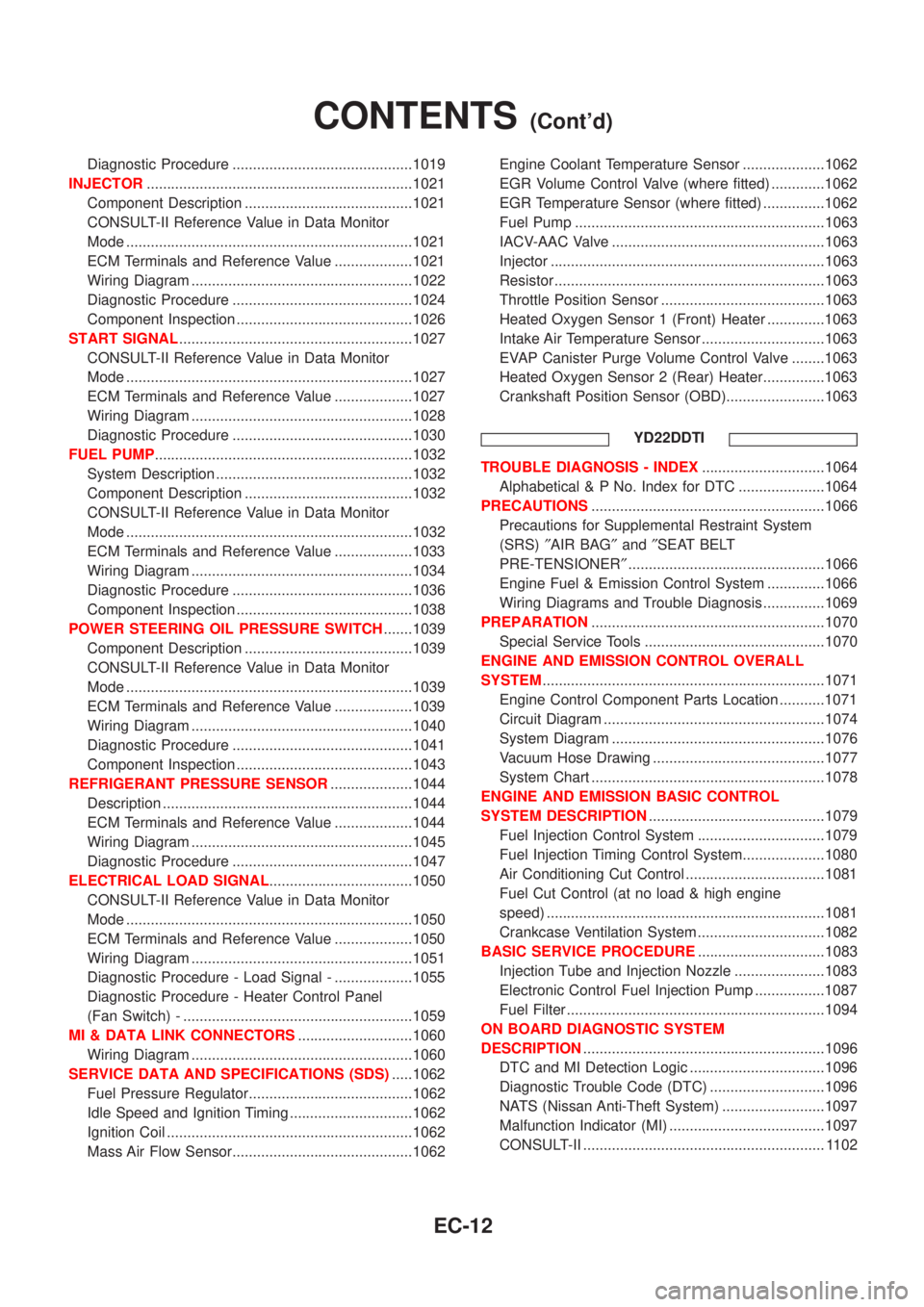
Diagnostic Procedure ............................................1019
INJECTOR.................................................................1021
Component Description .........................................1021
CONSULT-II Reference Value in Data Monitor
Mode ......................................................................1021
ECM Terminals and Reference Value ...................1021
Wiring Diagram ......................................................1022
Diagnostic Procedure ............................................1024
Component Inspection ...........................................1026
START SIGNAL.........................................................1027
CONSULT-II Reference Value in Data Monitor
Mode ......................................................................1027
ECM Terminals and Reference Value ...................1027
Wiring Diagram ......................................................1028
Diagnostic Procedure ............................................1030
FUEL PUMP...............................................................1032
System Description ................................................1032
Component Description .........................................1032
CONSULT-II Reference Value in Data Monitor
Mode ......................................................................1032
ECM Terminals and Reference Value ...................1033
Wiring Diagram ......................................................1034
Diagnostic Procedure ............................................1036
Component Inspection ...........................................1038
POWER STEERING OIL PRESSURE SWITCH.......1039
Component Description .........................................1039
CONSULT-II Reference Value in Data Monitor
Mode ......................................................................1039
ECM Terminals and Reference Value ...................1039
Wiring Diagram ......................................................1040
Diagnostic Procedure ............................................1041
Component Inspection ...........................................1043
REFRIGERANT PRESSURE SENSOR....................1044
Description .............................................................1044
ECM Terminals and Reference Value ...................1044
Wiring Diagram ......................................................1045
Diagnostic Procedure ............................................1047
ELECTRICAL LOAD SIGNAL...................................1050
CONSULT-II Reference Value in Data Monitor
Mode ......................................................................1050
ECM Terminals and Reference Value ...................1050
Wiring Diagram ......................................................1051
Diagnostic Procedure - Load Signal - ...................1055
Diagnostic Procedure - Heater Control Panel
(Fan Switch) - ........................................................1059
MI & DATA LINK CONNECTORS............................1060
Wiring Diagram ......................................................1060
SERVICE DATA AND SPECIFICATIONS (SDS).....1062
Fuel Pressure Regulator........................................1062
Idle Speed and Ignition Timing ..............................1062
Ignition Coil ............................................................1062
Mass Air Flow Sensor............................................1062Engine Coolant Temperature Sensor ....................1062
EGR Volume Control Valve (where fitted) .............1062
EGR Temperature Sensor (where fitted) ...............1062
Fuel Pump .............................................................1063
IACV-AAC Valve ....................................................1063
Injector ...................................................................1063
Resistor ..................................................................1063
Throttle Position Sensor ........................................1063
Heated Oxygen Sensor 1 (Front) Heater ..............1063
Intake Air Temperature Sensor ..............................1063
EVAP Canister Purge Volume Control Valve ........1063
Heated Oxygen Sensor 2 (Rear) Heater...............1063
Crankshaft Position Sensor (OBD)........................1063
YD22DDTI
TROUBLE DIAGNOSIS - INDEX..............................1064
Alphabetical & P No. Index for DTC .....................1064
PRECAUTIONS.........................................................1066
Precautions for Supplemental Restraint System
(SRS)²AIR BAG²and²SEAT BELT
PRE-TENSIONER²................................................1066
Engine Fuel & Emission Control System ..............1066
Wiring Diagrams and Trouble Diagnosis ...............1069
PREPARATION.........................................................1070
Special Service Tools ............................................1070
ENGINE AND EMISSION CONTROL OVERALL
SYSTEM.....................................................................1071
Engine Control Component Parts Location ...........1071
Circuit Diagram ......................................................1074
System Diagram ....................................................1076
Vacuum Hose Drawing ..........................................1077
System Chart .........................................................1078
ENGINE AND EMISSION BASIC CONTROL
SYSTEM DESCRIPTION...........................................1079
Fuel Injection Control System ...............................1079
Fuel Injection Timing Control System....................1080
Air Conditioning Cut Control ..................................1081
Fuel Cut Control (at no load & high engine
speed) ....................................................................1081
Crankcase Ventilation System ...............................1082
BASIC SERVICE PROCEDURE...............................1083
Injection Tube and Injection Nozzle ......................1083
Electronic Control Fuel Injection Pump .................1087
Fuel Filter ...............................................................1094
ON BOARD DIAGNOSTIC SYSTEM
DESCRIPTION...........................................................1096
DTC and MI Detection Logic .................................1096
Diagnostic Trouble Code (DTC) ............................1096
NATS (Nissan Anti-Theft System) .........................1097
Malfunction Indicator (MI) ......................................1097
CONSULT-II ........................................................... 1102
CONTENTS(Cont'd)
EC-12
Page 440 of 3051
SERVICE DATA AND SPECIFICATIONS (SDS).....1305
General Specifications ...........................................1305
Injection Nozzle .....................................................1305
Engine Coolant Temperature Sensor ....................1305Crankshaft Position Sensor (TDC) ........................1305
Glow Plug ..............................................................1305
Accelerator Position Sensor ..................................1305
EGR Volume Control Valve ...................................1305
CONTENTS(Cont'd)
EC-15
Page 459 of 3051
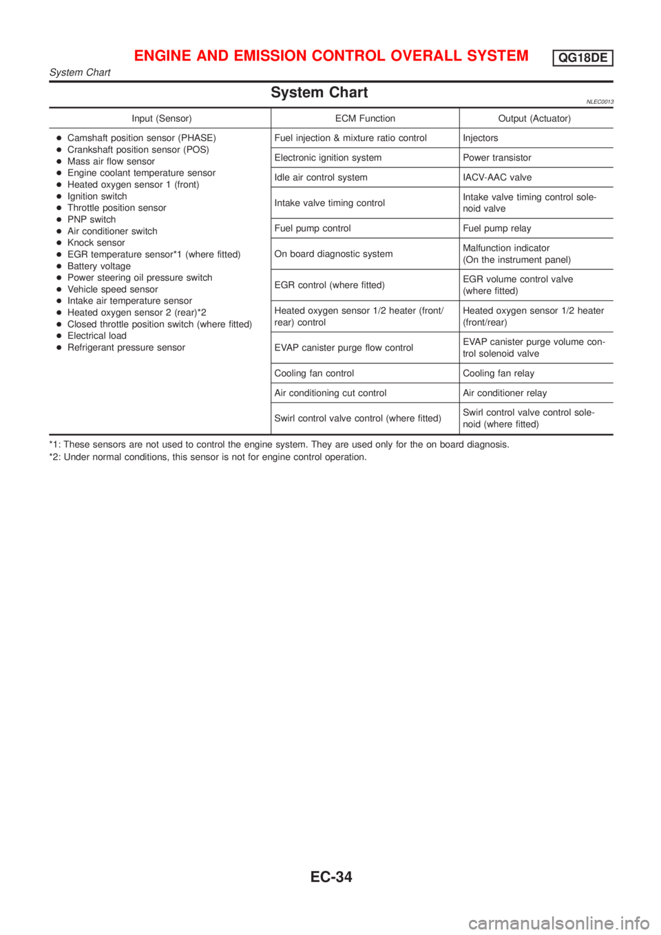
System ChartNLEC0013
Input (Sensor) ECM Function Output (Actuator)
+Camshaft position sensor (PHASE)
+Crankshaft position sensor (POS)
+Mass air flow sensor
+Engine coolant temperature sensor
+Heated oxygen sensor 1 (front)
+Ignition switch
+Throttle position sensor
+PNP switch
+Air conditioner switch
+Knock sensor
+EGR temperature sensor*1 (where fitted)
+Battery voltage
+Power steering oil pressure switch
+Vehicle speed sensor
+Intake air temperature sensor
+Heated oxygen sensor 2 (rear)*2
+Closed throttle position switch (where fitted)
+Electrical load
+Refrigerant pressure sensorFuel injection & mixture ratio control Injectors
Electronic ignition system Power transistor
Idle air control system IACV-AAC valve
Intake valve timing controlIntake valve timing control sole-
noid valve
Fuel pump control Fuel pump relay
On board diagnostic systemMalfunction indicator
(On the instrument panel)
EGR control (where fitted)EGR volume control valve
(where fitted)
Heated oxygen sensor 1/2 heater (front/
rear) controlHeated oxygen sensor 1/2 heater
(front/rear)
EVAP canister purge flow controlEVAP canister purge volume con-
trol solenoid valve
Cooling fan control Cooling fan relay
Air conditioning cut control Air conditioner relay
Swirl control valve control (where fitted)Swirl control valve control sole-
noid (where fitted)
*1: These sensors are not used to control the engine system. They are used only for the on board diagnosis.
*2: Under normal conditions, this sensor is not for engine control operation.
ENGINE AND EMISSION CONTROL OVERALL SYSTEMQG18DE
System Chart
EC-34
Page 460 of 3051
Multiport Fuel Injection (MFI) System
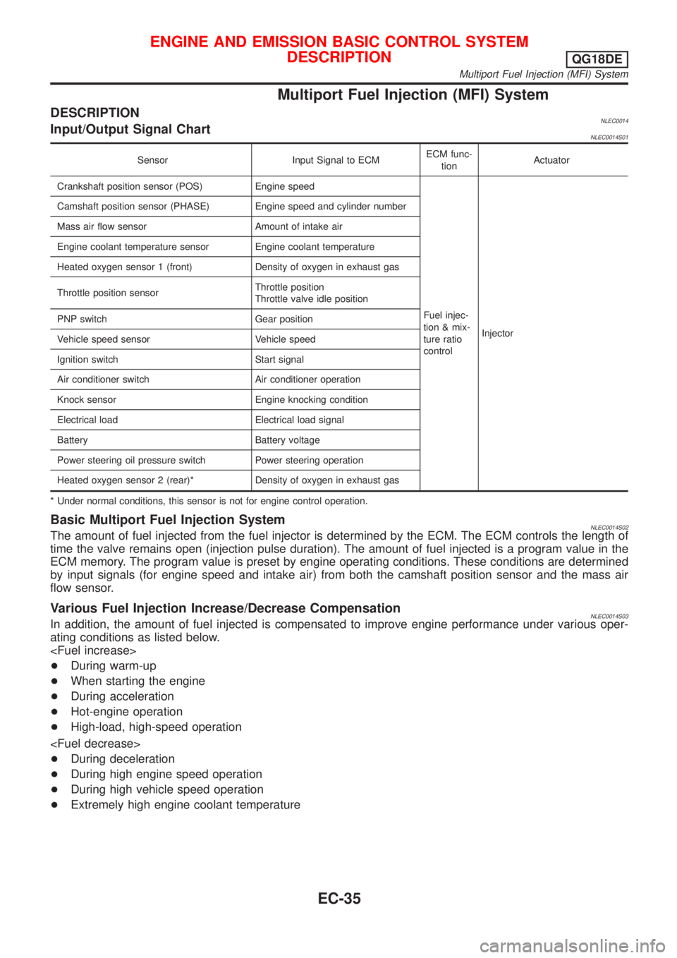
DESCRIPTIONNLEC0014Input/Output Signal ChartNLEC0014S01
Sensor Input Signal to ECMECM func-
tionActuator
Crankshaft position sensor (POS) Engine speed
Fuel injec-
tion & mix-
ture ratio
controlInjector Camshaft position sensor (PHASE) Engine speed and cylinder number
Mass air flow sensor Amount of intake air
Engine coolant temperature sensor Engine coolant temperature
Heated oxygen sensor 1 (front) Density of oxygen in exhaust gas
Throttle position sensorThrottle position
Throttle valve idle position
PNP switch Gear position
Vehicle speed sensor Vehicle speed
Ignition switch Start signal
Air conditioner switch Air conditioner operation
Knock sensor Engine knocking condition
Electrical load Electrical load signal
Battery Battery voltage
Power steering oil pressure switch Power steering operation
Heated oxygen sensor 2 (rear)* Density of oxygen in exhaust gas
* Under normal conditions, this sensor is not for engine control operation.
Basic Multiport Fuel Injection SystemNLEC0014S02The amount of fuel injected from the fuel injector is determined by the ECM. The ECM controls the length of
time the valve remains open (injection pulse duration). The amount of fuel injected is a program value in the
ECM memory. The program value is preset by engine operating conditions. These conditions are determined
by input signals (for engine speed and intake air) from both the camshaft position sensor and the mass air
flow sensor.
Various Fuel Injection Increase/Decrease CompensationNLEC0014S03In addition, the amount of fuel injected is compensated to improve engine performance under various oper-
ating conditions as listed below.
+During warm-up
+When starting the engine
+During acceleration
+Hot-engine operation
+High-load, high-speed operation
+During deceleration
+During high engine speed operation
+During high vehicle speed operation
+Extremely high engine coolant temperature
ENGINE AND EMISSION BASIC CONTROL SYSTEM
DESCRIPTION
QG18DE
Multiport Fuel Injection (MFI) System
EC-35