2001 NISSAN ALMERA TINO wheel bolts
[x] Cancel search: wheel boltsPage 53 of 3051
SAT513G
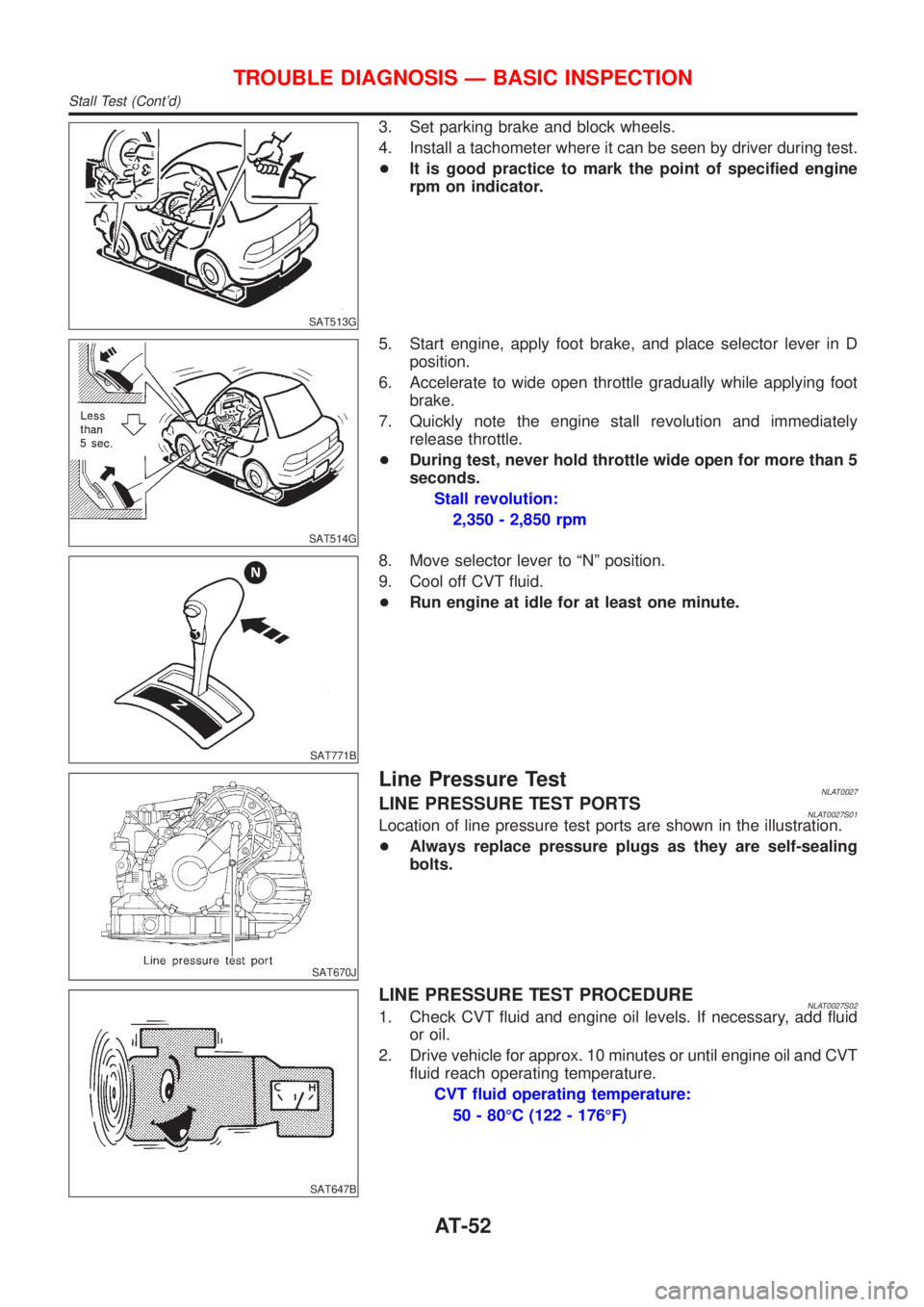
3. Set parking brake and block wheels.
4. Install a tachometer where it can be seen by driver during test.
+It is good practice to mark the point of specified engine
rpm on indicator.
SAT514G
5. Start engine, apply foot brake, and place selector lever in D
position.
6. Accelerate to wide open throttle gradually while applying foot
brake.
7. Quickly note the engine stall revolution and immediately
release throttle.
+During test, never hold throttle wide open for more than 5
seconds.
Stall revolution:
2,350 - 2,850 rpm
SAT771B
8. Move selector lever to ªNº position.
9. Cool off CVT fluid.
+Run engine at idle for at least one minute.
SAT670J
Line Pressure TestNLAT0027LINE PRESSURE TEST PORTSNLAT0027S01Location of line pressure test ports are shown in the illustration.
+Always replace pressure plugs as they are self-sealing
bolts.
SAT647B
LINE PRESSURE TEST PROCEDURENLAT0027S021. Check CVT fluid and engine oil levels. If necessary, add fluid
or oil.
2. Drive vehicle for approx. 10 minutes or until engine oil and CVT
fluid reach operating temperature.
CVT fluid operating temperature:
50 - 80ÉC (122 - 176ÉF)
TROUBLE DIAGNOSIS Ð BASIC INSPECTION
Stall Test (Cont'd)
AT-52
Page 205 of 3051
SAT658J
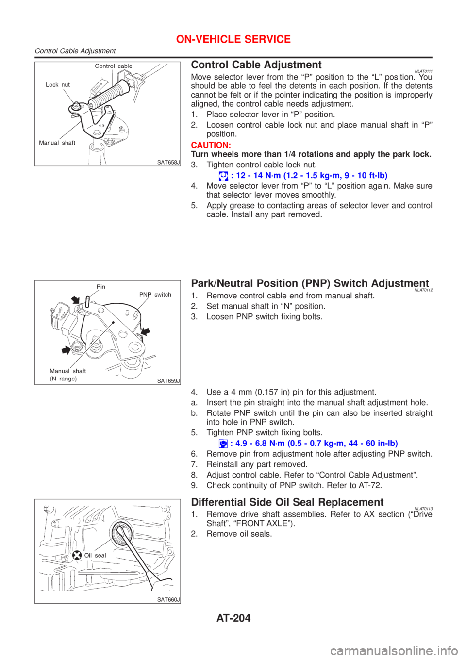
Control Cable AdjustmentNLAT0111Move selector lever from the ªPº position to the ªLº position. You
should be able to feel the detents in each position. If the detents
cannot be felt or if the pointer indicating the position is improperly
aligned, the control cable needs adjustment.
1. Place selector lever in ªPº position.
2. Loosen control cable lock nut and place manual shaft in ªPº
position.
CAUTION:
Turn wheels more than 1/4 rotations and apply the park lock.
3. Tighten control cable lock nut.
: 12 - 14 N´m (1.2 - 1.5 kg-m,9-10ft-lb)
4. Move selector lever from ªPº to ªLº position again. Make sure
that selector lever moves smoothly.
5. Apply grease to contacting areas of selector lever and control
cable. Install any part removed.
SAT659J
Park/Neutral Position (PNP) Switch AdjustmentNLAT01121. Remove control cable end from manual shaft.
2. Set manual shaft in ªNº position.
3. Loosen PNP switch fixing bolts.
4. Usea4mm(0.157 in) pin for this adjustment.
a. Insert the pin straight into the manual shaft adjustment hole.
b. Rotate PNP switch until the pin can also be inserted straight
into hole in PNP switch.
5. Tighten PNP switch fixing bolts.
: 4.9 - 6.8 N´m (0.5 - 0.7 kg-m, 44 - 60 in-lb)
6. Remove pin from adjustment hole after adjusting PNP switch.
7. Reinstall any part removed.
8. Adjust control cable. Refer to ªControl Cable Adjustmentº.
9. Check continuity of PNP switch. Refer to AT-72.
SAT660J
Differential Side Oil Seal ReplacementNLAT01131. Remove drive shaft assemblies. Refer to AX section (ªDrive
Shaftº, ªFRONT AXLEº).
2. Remove oil seals.
ON-VEHICLE SERVICE
Control Cable Adjustment
AT-204
Page 214 of 3051
Noise, Vibration and Harshness (NVH)
Troubleshooting
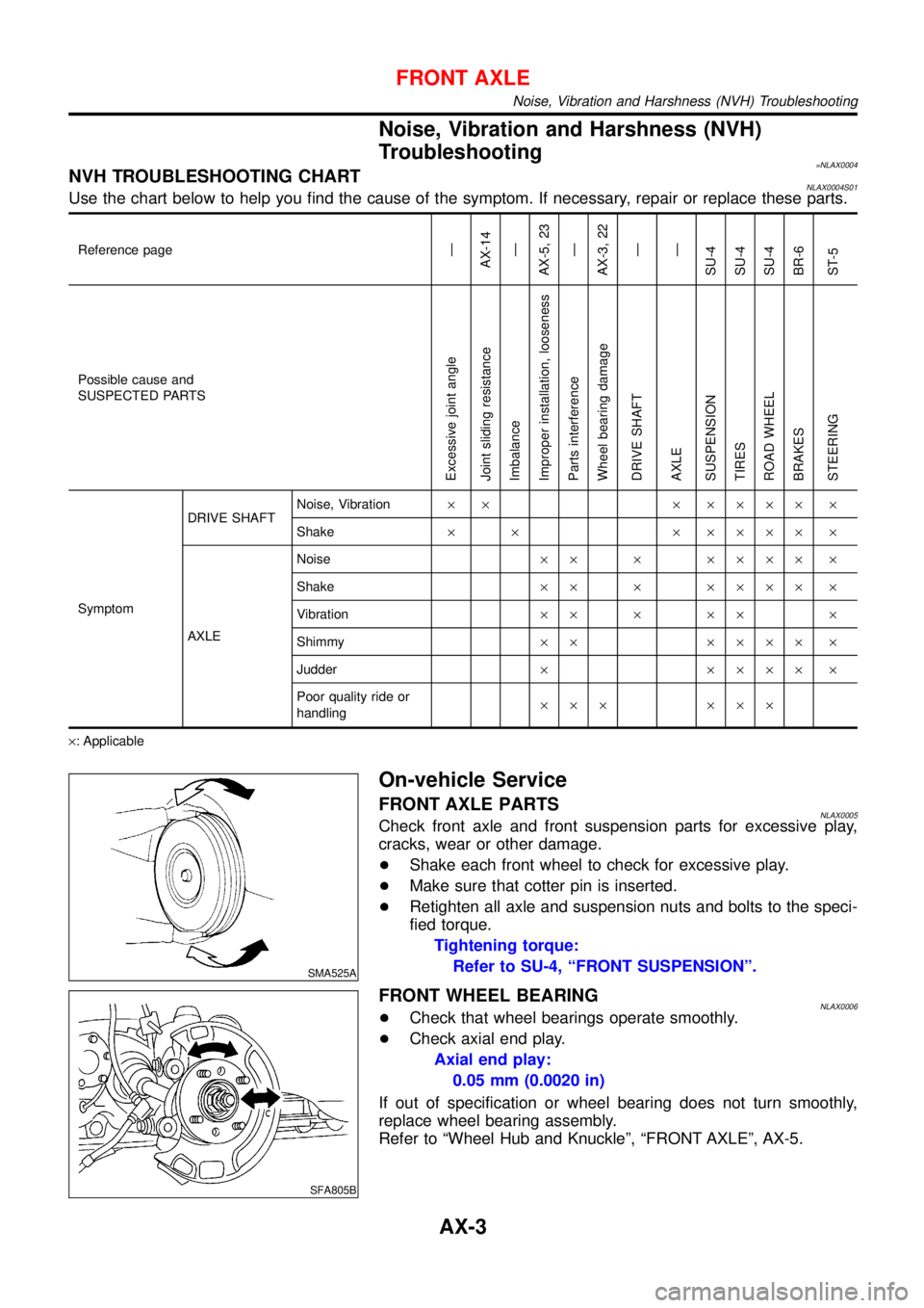
=NLAX0004NVH TROUBLESHOOTING CHARTNLAX0004S01Use the chart below to help you find the cause of the symptom. If necessary, repair or replace these parts.
Reference page—
AX-14
—
AX-5, 23
—
AX-3, 22
—
—
SU-4
SU-4
SU-4
BR-6
ST-5
Possible cause and
SUSPECTED PARTS
Excessive joint angle
Joint sliding resistance
Imbalance
Improper installation, looseness
Parts interference
Wheel bearing damage
DRIVE SHAFT
AXLE
SUSPENSION
TIRES
ROAD WHEEL
BRAKES
STEERING
SymptomDRIVE SHAFTNoise, Vibration× × × ×××× ×
Shake× × × ×××× ×
AXLENoise×× × ×××× ×
Shake×× × ×××× ×
Vibration×× × ×× ×
Shimmy×× ×××× ×
Judder× ×××× ×
Poor quality ride or
handling××× ×××
×: Applicable
SMA525A
On-vehicle Service
FRONT AXLE PARTSNLAX0005Check front axle and front suspension parts for excessive play,
cracks, wear or other damage.
+Shake each front wheel to check for excessive play.
+Make sure that cotter pin is inserted.
+Retighten all axle and suspension nuts and bolts to the speci-
fied torque.
Tightening torque:
Refer to SU-4, “FRONT SUSPENSION”.
SFA805B
FRONT WHEEL BEARINGNLAX0006+Check that wheel bearings operate smoothly.
+Check axial end play.
Axial end play:
0.05 mm (0.0020 in)
If out of specification or wheel bearing does not turn smoothly,
replace wheel bearing assembly.
Refer to “Wheel Hub and Knuckle”, “FRONT AXLE”, AX-5.
FRONT AXLE
Noise, Vibration and Harshness (NVH) Troubleshooting
AX-3
Page 217 of 3051

SFA898A
2. Remove brake caliper assembly and rotor.
Brake hose need not be disconnected from brake caliper. In
this case, suspend caliper assembly with wire so as not to
stretch brake hose. Be careful not to depress brake pedal, or
piston will pop out.
Make sure brake hose is not twisted.
SFA372-A
3. Separate tie-rod from knuckle with Tool.
Install stud nut on stud bolt to prevent damage to stud bolt.
SFA181A
4. Separate drive shaft from knuckle by lightly tapping it. If it is
hard to remove, use a puller.
Cover boots with shop towel so as not to damage them when
removing drive shaft.
SFA153B
5. Remove strut lower mounting bolts.
SFA113AC
6. Loosen lower ball joint tightening nut.
7. Separate knuckle from lower ball joint stud with Tool.
8. Remove knuckle from transverse link.
FRONT AXLE
Wheel Hub and Knuckle (Cont’d)
AX-6
Page 218 of 3051
SFA114A
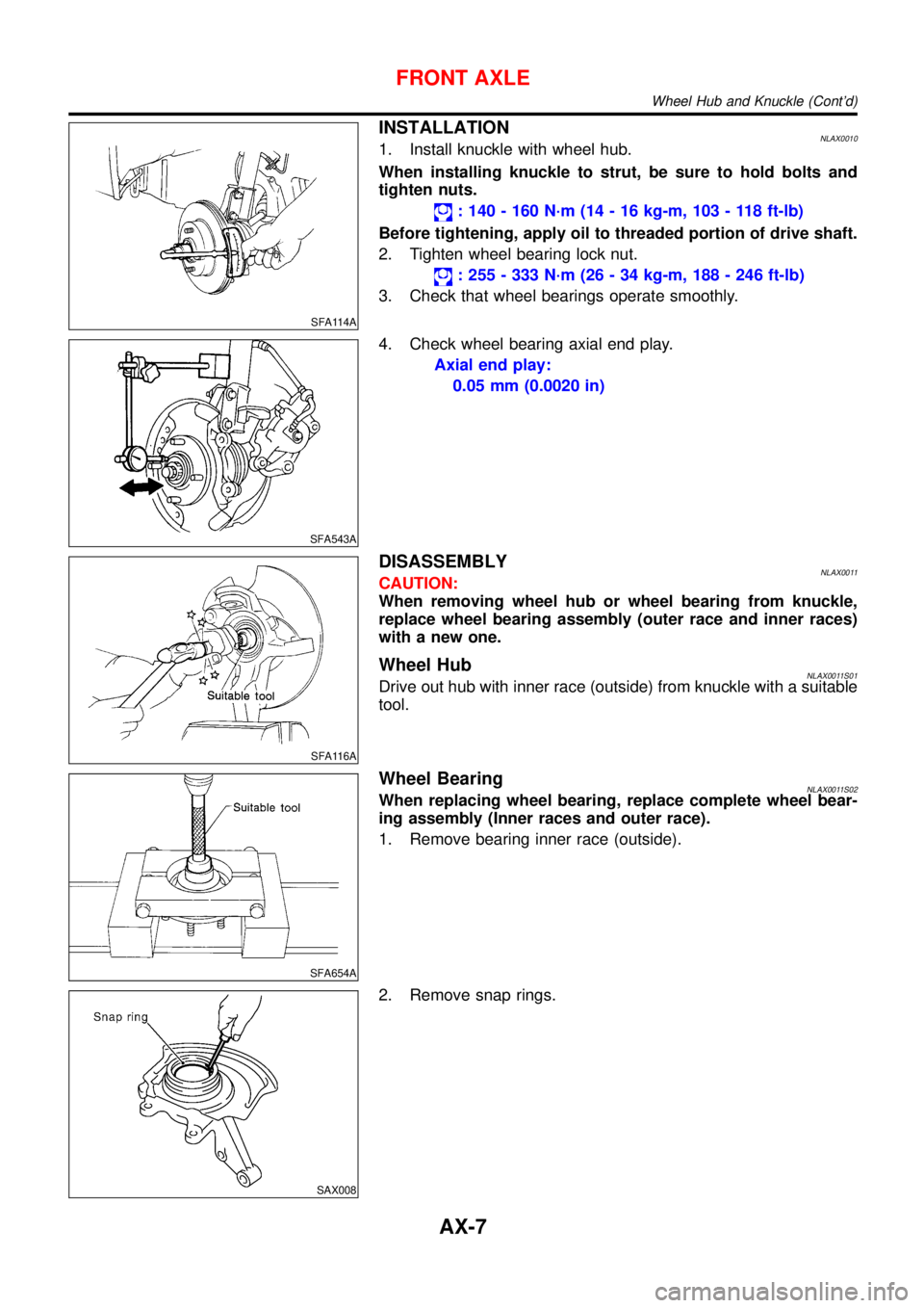
INSTALLATIONNLAX00101. Install knuckle with wheel hub.
When installing knuckle to strut, be sure to hold bolts and
tighten nuts.
: 140 - 160 N·m (14 - 16 kg-m, 103 - 118 ft-lb)
Before tightening, apply oil to threaded portion of drive shaft.
2. Tighten wheel bearing lock nut.
: 255 - 333 N·m (26 - 34 kg-m, 188 - 246 ft-lb)
3. Check that wheel bearings operate smoothly.
SFA543A
4. Check wheel bearing axial end play.
Axial end play:
0.05 mm (0.0020 in)
SFA116A
DISASSEMBLYNLAX0011CAUTION:
When removing wheel hub or wheel bearing from knuckle,
replace wheel bearing assembly (outer race and inner races)
with a new one.
Wheel HubNLAX0011S01Drive out hub with inner race (outside) from knuckle with a suitable
tool.
SFA654A
Wheel BearingNLAX0011S02When replacing wheel bearing, replace complete wheel bear-
ing assembly (Inner races and outer race).
1. Remove bearing inner race (outside).
SAX008
2. Remove snap rings.
FRONT AXLE
Wheel Hub and Knuckle (Cont’d)
AX-7
Page 222 of 3051

SFA090A
REMOVALNLAX00141. Remove wheel bearing lock nut.
Brake caliper need not be disconnected. Do not twist or
stretch brake hose when moving components.
SFA153B
2. Remove strut lower mount bolts.
3. Remove brake hose clip.
SFA499A
4. Separate drive shaft from knuckle by lightly tapping it. If it is
hard to remove, use a puller.
Cover boots with shop towel so as not to damage them
when removing drive shaft.
Refer to“Wheel Hub and Knuckle”,“FRONT AXLE”, AX-5.
5. Remove right drive shaft from transaxle.
NAX004
6. Remove left drive shaft from transaxle.
+Pry off drive shaft from transaxle as shown at left.
SFA482-D
INSTALLATIONNLAX0015Transaxle SideNLAX0015S011. Drive a new oil seal to transaxle. Refer to MT-15 or AT-204,
“Replacing Oil Seal”or“Differential Side Oil Seal
Replacement”,“ON-VEHICLE SERVICE”.
2. Set Tool along the inner circumference of oil seal.
FRONT AXLE
Drive Shaft (Cont’d)
AX-11
Page 276 of 3051

SBR219C
ROTORNLBR0154S02Rubbing SurfaceNLBR0154S0201Check rotor for roughness, cracks or chips.
RunoutNLBR0154S02021. Secure rotor to wheel hub with two nuts (M12 x 1.25).
2. Check runout using a dial indicator.
Make sure that axial end play is within the specifications
before measuring. Refer to AX section (“REAR WHEEL
BEARING”,“On-vehicle Service”).
3. Change relative positions of rotor and wheel hub so that runout
is minimized.
Maximum runout:
0.07 mm (0.0028 in)
ThicknessNLBR0154S0203Rotor repair limit:
Standard thickness
10 mm (0.39 in)
Minimum thickness
9 mm (0.35 in)
Thickness variation (At least 8 portions)
Maximum 0.02 mm (0.0008 in)
NBR374
NBR375
InstallationNLBR0156CAUTION:
+Refill with new brake fluid“DOT 4”.
+Never reuse drained brake fluid.
+Do not drain (factory) filled brake fluid from (new) caliper
assemblies.
1. Install caliper assembly.
+As shown in the figure, align the piston’s concave to the pad’s
convex, then install the cylinder body to the torque member.
2. Remove the plug from the cylinder body and brake hose.
CAUTION:
Care should be taken as not to let:
+Air enter the cylinder body and brake hose.
+Brake fluid spill from the cylinder body and brake hose.
3. Install brake hose to caliper securely.
4. Install all parts and secure all bolts.
5. Bleed air. Refer to“Bleeding Brake System”, BR-8 and“Air
Bleeding Procedure”, CL-10.
REAR DISC BRAKE (BALL & RAMP TYPE)
Inspection (Cont’d)
BR-39
Page 338 of 3051
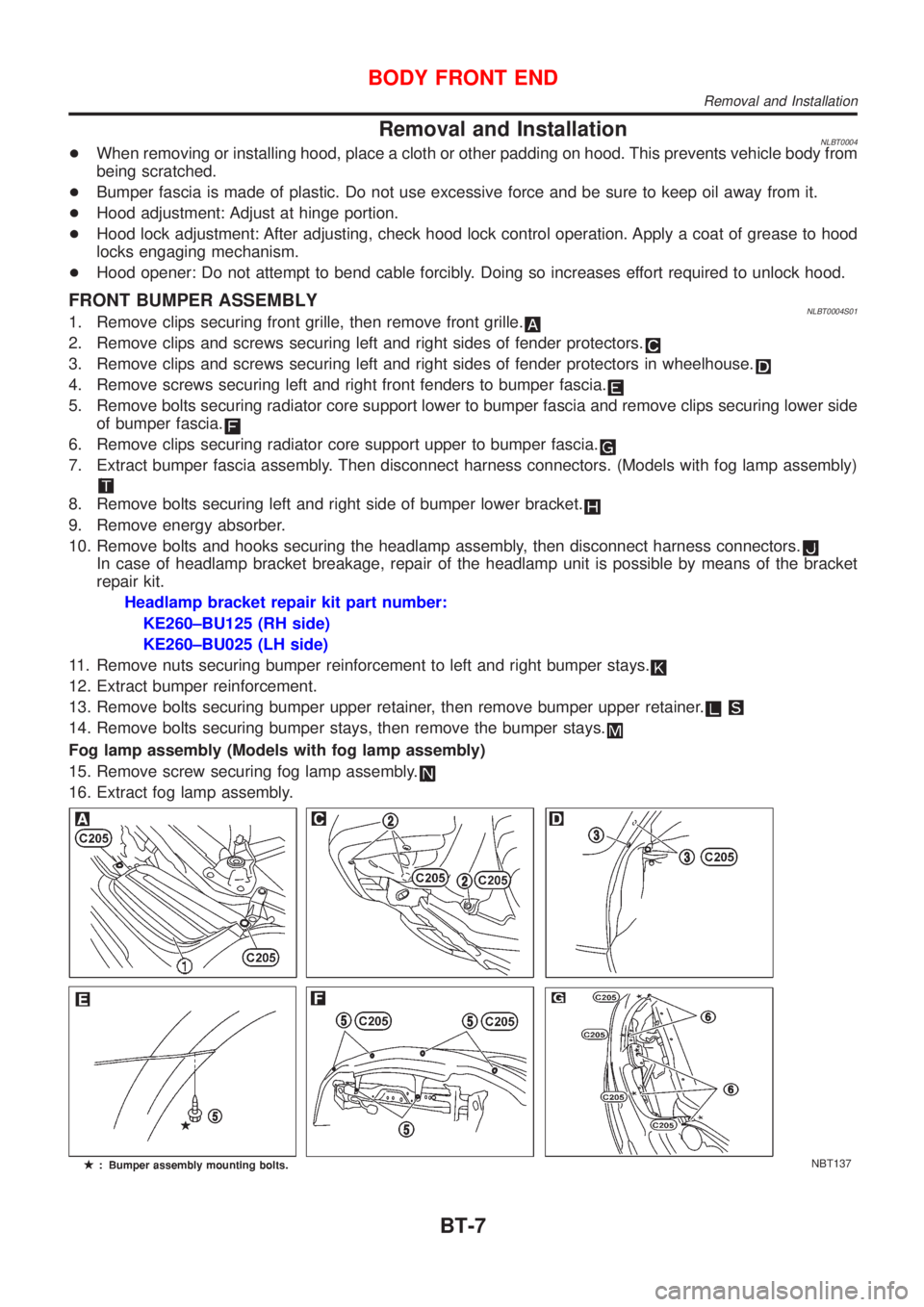
Removal and InstallationNLBT0004+When removing or installing hood, place a cloth or other padding on hood. This prevents vehicle body from
being scratched.
+Bumper fascia is made of plastic. Do not use excessive force and be sure to keep oil away from it.
+Hood adjustment: Adjust at hinge portion.
+Hood lock adjustment: After adjusting, check hood lock control operation. Apply a coat of grease to hood
locks engaging mechanism.
+Hood opener: Do not attempt to bend cable forcibly. Doing so increases effort required to unlock hood.
FRONT BUMPER ASSEMBLYNLBT0004S011. Remove clips securing front grille, then remove front grille.
2. Remove clips and screws securing left and right sides of fender protectors.
3. Remove clips and screws securing left and right sides of fender protectors in wheelhouse.
4. Remove screws securing left and right front fenders to bumper fascia.
5. Remove bolts securing radiator core support lower to bumper fascia and remove clips securing lower side
of bumper fascia.
6. Remove clips securing radiator core support upper to bumper fascia.
7. Extract bumper fascia assembly. Then disconnect harness connectors. (Models with fog lamp assembly)
8. Remove bolts securing left and right side of bumper lower bracket.
9. Remove energy absorber.
10. Remove bolts and hooks securing the headlamp assembly, then disconnect harness connectors.
In case of headlamp bracket breakage, repair of the headlamp unit is possible by means of the bracket
repair kit.
Headlamp bracket repair kit part number:
KE260±BU125 (RH side)
KE260±BU025 (LH side)
11. Remove nuts securing bumper reinforcement to left and right bumper stays.
12. Extract bumper reinforcement.
13. Remove bolts securing bumper upper retainer, then remove bumper upper retainer.
14. Remove bolts securing bumper stays, then remove the bumper stays.
Fog lamp assembly (Models with fog lamp assembly)
15. Remove screw securing fog lamp assembly.
16. Extract fog lamp assembly.
NBT137
BODY FRONT END
Removal and Installation
BT-7