2001 NISSAN ALMERA TINO wiper relay
[x] Cancel search: wiper relayPage 1907 of 3051

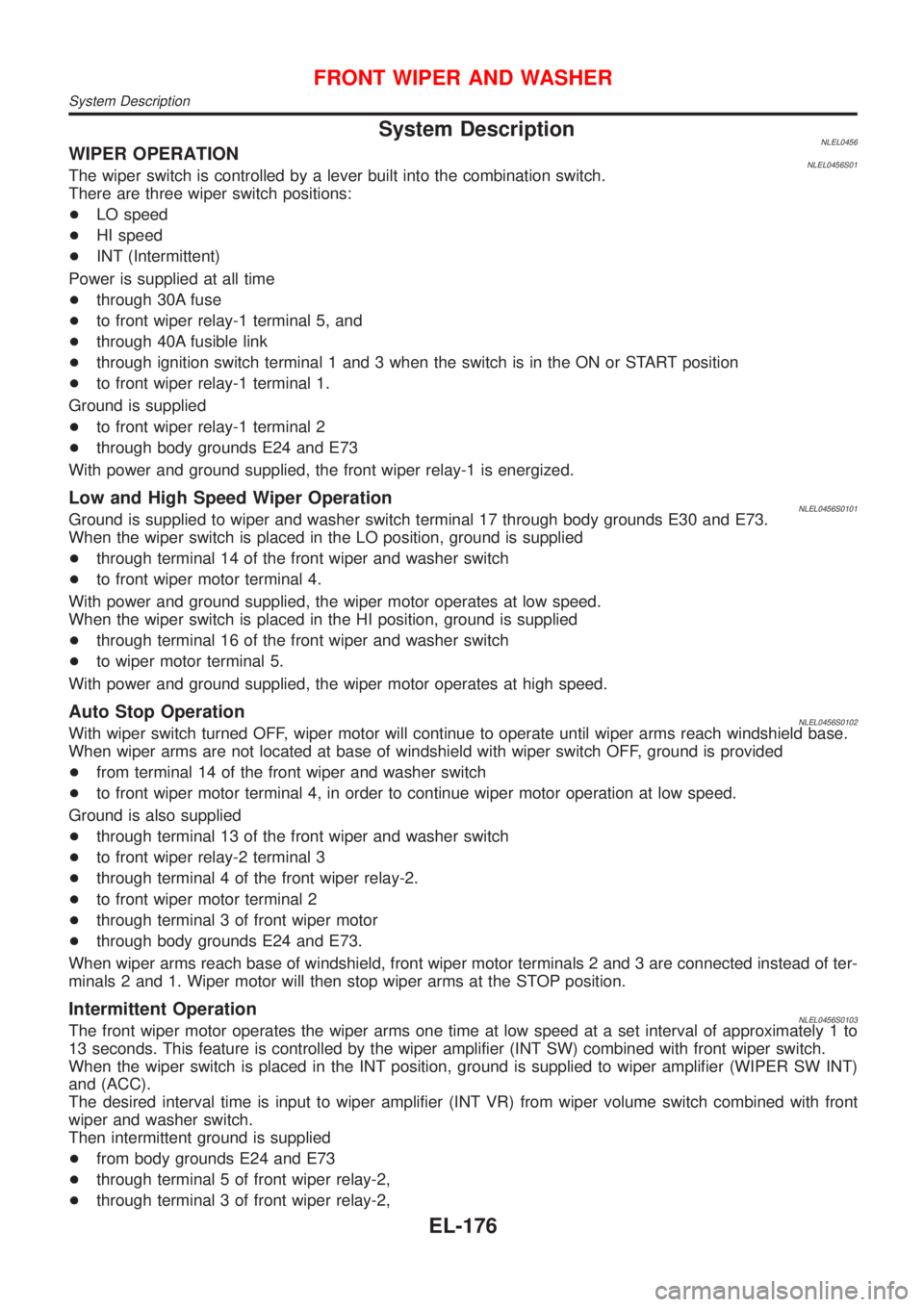
System DescriptionNLEL0456WIPER OPERATIONNLEL0456S01The wiper switch is controlled by a lever built into the combination switch.
There are three wiper switch positions:
+LO speed
+HI speed
+INT (Intermittent)
Power is supplied at all time
+through 30A fuse
+to front wiper relay-1 terminal 5, and
+through 40A fusible link
+through ignition switch terminal 1 and 3 when the switch is in the ON or START position
+to front wiper relay-1 terminal 1.
Ground is supplied
+to front wiper relay-1 terminal 2
+through body grounds E24 and E73
With power and ground supplied, the front wiper relay-1 is energized.
Low and High Speed Wiper OperationNLEL0456S0101Ground is supplied to wiper and washer switch terminal 17 through body grounds E30 and E73.
When the wiper switch is placed in the LO position, ground is supplied
+through terminal 14 of the front wiper and washer switch
+to front wiper motor terminal 4.
With power and ground supplied, the wiper motor operates at low speed.
When the wiper switch is placed in the HI position, ground is supplied
+through terminal 16 of the front wiper and washer switch
+to wiper motor terminal 5.
With power and ground supplied, the wiper motor operates at high speed.
Auto Stop OperationNLEL0456S0102With wiper switch turned OFF, wiper motor will continue to operate until wiper arms reach windshield base.
When wiper arms are not located at base of windshield with wiper switch OFF, ground is provided
+from terminal 14 of the front wiper and washer switch
+to front wiper motor terminal 4, in order to continue wiper motor operation at low speed.
Ground is also supplied
+through terminal 13 of the front wiper and washer switch
+to front wiper relay-2 terminal 3
+through terminal 4 of the front wiper relay-2.
+to front wiper motor terminal 2
+through terminal 3 of front wiper motor
+through body grounds E24 and E73.
When wiper arms reach base of windshield, front wiper motor terminals 2 and 3 are connected instead of ter-
minals 2 and 1. Wiper motor will then stop wiper arms at the STOP position.
Intermittent OperationNLEL0456S0103The front wiper motor operates the wiper arms one time at low speed at a set interval of approximately 1 to
13 seconds. This feature is controlled by the wiper amplifier (INT SW) combined with front wiper switch.
When the wiper switch is placed in the INT position, ground is supplied to wiper amplifier (WIPER SW INT)
and (ACC).
The desired interval time is input to wiper amplifier (INT VR) from wiper volume switch combined with front
wiper and washer switch.
Then intermittent ground is supplied
+from body grounds E24 and E73
+through terminal 5 of front wiper relay-2,
+through terminal 3 of front wiper relay-2,
FRONT WIPER AND WASHER
System Description
EL-176
Page 1908 of 3051

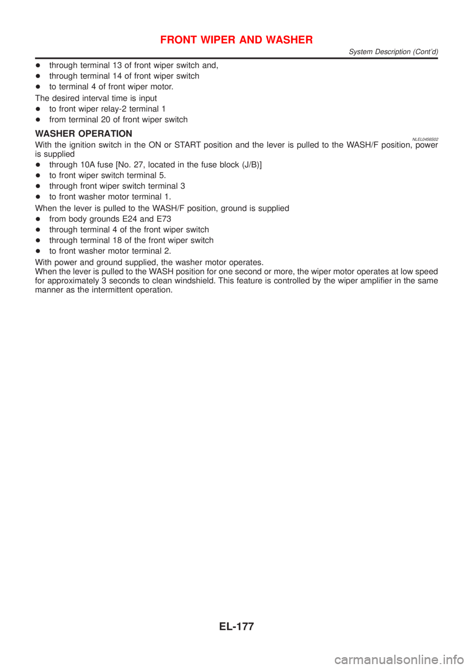
+through terminal 13 of front wiper switch and,
+through terminal 14 of front wiper switch
+to terminal 4 of front wiper motor.
The desired interval time is input
+to front wiper relay-2 terminal 1
+from terminal 20 of front wiper switch
WASHER OPERATIONNLEL0456S02With the ignition switch in the ON or START position and the lever is pulled to the WASH/F position, power
is supplied
+through 10A fuse [No. 27, located in the fuse block (J/B)]
+to front wiper switch terminal 5.
+through front wiper switch terminal 3
+to front washer motor terminal 1.
When the lever is pulled to the WASH/F position, ground is supplied
+from body grounds E24 and E73
+through terminal 4 of the front wiper switch
+through terminal 18 of the front wiper switch
+to front washer motor terminal 2.
With power and ground supplied, the washer motor operates.
When the lever is pulled to the WASH position for one second or more, the wiper motor operates at low speed
for approximately 3 seconds to clean windshield. This feature is controlled by the wiper amplifier in the same
manner as the intermittent operation.
FRONT WIPER AND WASHER
System Description (Cont'd)
EL-177
Page 2699 of 3051

Engine control component parts
location ................................ EC-26, 560, 1071
Engine control module (ECM) ........ EC-358, 880
Engine control system diagram and
chart .................................... EC-32, 566, 1076
Engine coolant temperature sensor
(ECTS) .............................. EC-169, 694, 1150
Engine fail-safe system .................. EC-123, 647
Engine oil precautions .................................. GI-7
Engine outer component parts ........... EM-12, 82
Engine removal ........................ EM-49, 130, 218
Engine room - See Engine
compartment .......................................... BT-66
Engine serial number ................................. GI-39
Evaporative emission (EVAP)
system ........................................... EC-39, 573
Exhaust gas recirculation (EGR)
valve ........... EC-310, 393, 446, 834, 921, 975
Exhaust system ................................... FE-11, 23
Exterior ...................................................... BT-38
F
F/PUMP - Wiring diagram ............. EC-518, 1034
FR02 - Wiring diagram .. EC-187, 207, 216, 415,
712, 732, 741, 945
FR02/H - Wiring diagram ............... EC-223, 422,
748, 952
FUEL - Wiring diagram ... EC-271, 279, 794, 802
Fan switch ................................................. HA-61
Final drive (FF M/T) ...................... MT-47, 63, 77
Finisher, interior - See Trim ....................... BT-28
Finisher, trunk lid ....................................... BT-31
Floor trim ................................................... BT-28
Fluids ........................................................ MA-20
Flywheel (clutch) ....................................... CL-22
Flywheel runout ........................ EM-60, 142, 235
Fog lamp, front, removal and
installation ................................................ BT-7
Fog lamp, front .......................................... EL-95
Fork rod (M/T) ..................................... MT-26, 64
Freeze frame data .............. EC-61, 71, 585, 596
Front axle .................................................... AX-2
Front bumper ............................................... BT-7
Front combination lamp removal and
installation ................................................ BT-7
Front disc brake ........................................ BR-24
Front door .................................................. BT-13
Front fog lamp removal and
installation ................................................ BT-7
Front fog lamp ........................................... EL-95
Front heated oxygen sensor (HO2S)
heater .......................... EC-221, 421, 746, 951
Front heated oxygen sensor (HO2S) ..... EC-184,
192, 198, 204, 214, 414, 709,
717, 723, 729, 739, 944Front seat belt ............................................. RS-5
Front seat .................................................. BT-46
Front suspension ........................................ SU-2
Front washer ............................................ EL-176
Front wiper ............................................... EL-176
Fuel cut control (at no load & high
engine speed) ..................... EC-39, 573, 1081
Fuel gauge ............................................... EL-130
Fuel injection system ............. EC-269, 277, 792,
800, 1079
Fuel injector .................................. EC-494, 1021
Fuel precautions ........................................... GI-8
Fuel pressure check ......................... EC-43, 577
Fuel pressure regulator .................... EC-44, 578
Fuel pressure release ....................... EC-43, 577
Fuel pump relay ............................ EC-516, 1032
Fuel pump ..................................... EC-516, 1032
Fuel system ........................................... FE-5, 15
Fuel tank vacuum relief valve ........... EC-40, 574
Fuse block ............................................... EL-527
Fuse ........................................................... EL-32
Fusible link ................................................. EL-32G
GLOW - Wiring diagram ....................... EC-1267
Garage jack and safety stand .................... GI-43
Gauges .................................................... EL-130
Gear components (M/T) ..................... MT-25, 63
Generator - See Alternator ....................... SC-28
Generic scan tool (GST) ................... EC-93, 617
Glass .......................................................... BT-14
Glow plug .............................................. EC-1267
Glow relay ............................................. EC-1267
Grease ...................................................... MA-20
Ground distribution .............................. EL-33, 48
H
H/LAMP - Wiring diagram .......................... EL-69
HEATER - Wiring diagram ........................ HA-23
HFC134a (R134a) system
precaution ................................................ HA-2
HFC134a (R134a) system service
procedure .............................................. HA-85
HFC134a (R134a) system service
tools ....................................................... HA-10
HFC134a system service equipment
precaution ................................................ HA-6
HORN - Wiring diagram .......................... EL-193
HSEAT - Wiring diagram ......................... EL-234
Harness connector ...................................... EL-5
Harness layout ......................................... EL-452
Hazard warning lamp .............................. EL-101
Headlamp removal and installation ............. BT-7
Headlamp washer .................................... EL-190
ALPHABETICAL INDEX
IDX-4