2001 NISSAN ALMERA TINO heater
[x] Cancel search: heaterPage 1 of 3051

Release:April 2001 01)GENERALINFORMATIONGIMAINTENANCEMAENGINEMECHANICALEMENGINELUBRICATION&
COOLINGSYSTEMSLCENGINECONTROLSYSTEMECACCELERATORCONTROL,
FUEL&EXHAUSTSYSTEMSFECLUTCHCLMANUALTRANSAXLEMTAUTOMATICTRANSAXLEATFRONT&REARAXLEAXFRONT&REARSUSPENSIONSUBRAKESYSTEMBRSTEERINGSYSTEMSTRESTRAINTSYSTEMRSBODY&TRIMBTHEATER&AIRCONDITIONERHASTARTING&CHARGINGSYSTEMSSCELECTRICALSYSTEMELALPHABETICALINDEXIDXALMERATINOMODELV10SERIESQUICKREFERENCEINDEX
Page 427 of 3051
DTC P0100 MASS AIR FLOW SENSOR (MAFS)......154
Component Description ...........................................154
CONSULT-II Reference Value in Data Monitor
Mode ........................................................................154
ECM Terminals and Reference Value .....................154
On Board Diagnosis Logic.......................................154
Fail-safe Mode .........................................................155
DTC Confirmation Procedure ..................................155
Wiring Diagram ........................................................156
Diagnostic Procedure ..............................................158
Component Inspection .............................................160
DTC P0110 INTAKE AIR TEMPERATURE
SENSOR......................................................................161
Component Description ...........................................161
On Board Diagnosis Logic.......................................162
DTC Confirmation Procedure ..................................162
Wiring Diagram ........................................................163
Diagnostic Procedure ..............................................165
Component Inspection .............................................167
DTC P0115 ENGINE COOLANT TEMPERATURE
SENSOR (ECTS) (CIRCUIT).......................................169
Component Description ...........................................169
CONSULT-II Reference Value in Data Monitor
Mode ........................................................................169
On Board Diagnosis Logic.......................................169
Fail-safe Mode .........................................................170
DTC Confirmation Procedure ..................................170
Wiring Diagram ........................................................171
Diagnostic Procedure ..............................................173
Component Inspection .............................................174
DTC P0120 THROTTLE POSITION SENSOR...........175
Component Description ...........................................175
CONSULT-II Reference Value in Data Monitor
Mode ........................................................................175
ECM Terminals and Reference Value .....................176
On Board Diagnosis Logic.......................................176
Fail-safe Mode .........................................................176
DTC Confirmation Procedure ..................................176
Wiring Diagram ........................................................178
Diagnostic Procedure ..............................................180
Component Inspection .............................................182
DTC P0130 HEATED OXYGEN SENSOR 1
(FRONT) (CIRCUIT).....................................................184
Component Description ...........................................184
CONSULT-II Reference Value in Data Monitor
Mode ........................................................................184
ECM Terminals and Reference Value .....................184
On Board Diagnosis Logic.......................................185
DTC Confirmation Procedure ..................................185
Overall Function Check ...........................................186
Wiring Diagram ........................................................187
Diagnostic Procedure ..............................................189Component Inspection .............................................190
DTC P0131 HEATED OXYGEN SENSOR 1
(FRONT) (LEAN SHIFT MONITORING).....................192
Component Description ...........................................192
CONSULT-II Reference Value in Data Monitor
Mode ........................................................................192
ECM Terminals and Reference Value .....................192
On Board Diagnosis Logic.......................................193
DTC Confirmation Procedure ..................................193
Overall Function Check ...........................................194
Diagnostic Procedure ..............................................194
Component Inspection .............................................196
DTC P0132 HEATED OXYGEN SENSOR 1
(FRONT) (RICH SHIFT MONITORING)......................198
Component Description ...........................................198
CONSULT-II Reference Value in Data Monitor
Mode ........................................................................198
ECM Terminals and Reference Value .....................198
On Board Diagnosis Logic.......................................199
DTC Confirmation Procedure ..................................199
Overall Function Check ...........................................200
Diagnostic Procedure ..............................................200
Component Inspection .............................................202
DTC P0133 HEATED OXYGEN SENSOR 1
(FRONT) (RESPONSE MONITORING).......................204
Component Description ...........................................204
CONSULT-II Reference Value in Data Monitor
Mode ........................................................................204
ECM Terminals and Reference Value .....................204
On Board Diagnosis Logic.......................................205
DTC Confirmation Procedure ..................................205
Overall Function Check ...........................................206
Wiring Diagram ........................................................207
Diagnostic Procedure ..............................................209
Component Inspection .............................................212
DTC P0134 HEATED OXYGEN SENSOR 1
(FRONT) (HIGH VOLTAGE)........................................214
Component Description ...........................................214
CONSULT-II Reference Value in Data Monitor
Mode ........................................................................214
ECM Terminals and Reference Value .....................214
On Board Diagnosis Logic.......................................215
DTC Confirmation Procedure ..................................215
Wiring Diagram ........................................................216
Diagnostic Procedure ..............................................218
Component Inspection .............................................219
DTC P0135 HEATED OXYGEN SENSOR 1
(FRONT) HEATER.......................................................221
Description ...............................................................221
CONSULT-II Reference Value in Data Monitor
Mode ........................................................................221
ECM Terminals and Reference Value .....................221
CONTENTS(Cont'd)
EC-2
Page 428 of 3051
On Board Diagnosis Logic.......................................221
DTC Confirmation Procedure ..................................222
Wiring Diagram ........................................................223
Diagnostic Procedure ..............................................225
Component Inspection .............................................226
DTC P0137 HEATED OXYGEN SENSOR 2
(REAR) (MIN. VOLTAGE MONITORING)...................227
Component Description ...........................................227
CONSULT-II Reference Value in Data Monitor
Mode ........................................................................227
ECM Terminals and Reference Value .....................227
On Board Diagnosis Logic.......................................227
DTC Confirmation Procedure ..................................228
Overall Function Check ...........................................229
Wiring Diagram ........................................................230
Diagnostic Procedure ..............................................232
Component Inspection .............................................235
DTC P0138 HEATED OXYGEN SENSOR 2
(REAR) (MAX. VOLTAGE MONITORING).................237
Component Description ...........................................237
CONSULT-II Reference Value in Data Monitor
Mode ........................................................................237
ECM Terminals and Reference Value .....................237
On Board Diagnosis Logic.......................................237
DTC Confirmation Procedure ..................................238
Overall Function Check ...........................................239
Wiring Diagram ........................................................240
Diagnostic Procedure ..............................................242
Component Inspection .............................................244
DTC P0139 HEATED OXYGEN SENSOR 2
(REAR) (RESPONSE MONITORING).........................246
Component Description ...........................................246
CONSULT-II Reference Value in Data Monitor
Mode ........................................................................246
ECM Terminals and Reference Value .....................246
On Board Diagnosis Logic.......................................246
DTC Confirmation Procedure ..................................247
Overall Function Check ...........................................248
Wiring Diagram ........................................................249
Diagnostic Procedure ..............................................251
Component Inspection .............................................254
DTC P0140 HEATED OXYGEN SENSOR 2
(REAR) (HIGH VOLTAGE)..........................................256
Component Description ...........................................256
CONSULT-II Reference Value in Data Monitor
Mode ........................................................................256
ECM Terminals and Reference Value .....................256
On Board Diagnosis Logic.......................................256
DTC Confirmation Procedure ..................................257
Overall Function Check ...........................................257
Wiring Diagram ........................................................258
Diagnostic Procedure ..............................................260Component Inspection .............................................261
DTC P0141 HEATED OXYGEN SENSOR 2
HEATER (REAR).........................................................263
Description ...............................................................263
CONSULT-II Reference Value in Data Monitor
Mode ........................................................................263
ECM Terminals and Reference Value .....................263
On Board Diagnosis Logic.......................................264
DTC Confirmation Procedure ..................................264
Wiring Diagram ........................................................265
Diagnostic Procedure ..............................................267
Component Inspection .............................................268
DTC P0171 FUEL INJECTION SYSTEM
FUNCTION (LEAN SIDE)............................................269
On Board Diagnosis Logic.......................................269
DTC Confirmation Procedure ..................................269
Wiring Diagram ........................................................271
Diagnostic Procedure ..............................................273
DTC P0172 FUEL INJECTION SYSTEM
FUNCTION (RICH SIDE).............................................277
On Board Diagnosis Logic.......................................277
DTC Confirmation Procedure ..................................277
Wiring Diagram ........................................................279
Diagnostic Procedure ..............................................281
DTC P0300 - P0304 NO.4-1CYLINDER
MISFIRE, MULTIPLE CYLINDER MISFIRE...............285
On Board Diagnosis Logic.......................................285
DTC Confirmation Procedure ..................................285
Diagnostic Procedure ..............................................286
DTC P0325 KNOCK SENSOR (KS)...........................291
Component Description ...........................................291
ECM Terminals and Reference Value .....................291
On Board Diagnosis Logic.......................................291
DTC Confirmation Procedure ..................................291
Wiring Diagram ........................................................292
Diagnostic Procedure ..............................................293
Component Inspection .............................................294
DTC P0335 CRANKSHAFT POSITION SENSOR
(POS)............................................................................295
Component Description ...........................................295
ECM Terminals and Reference Value .....................295
On Board Diagnosis Logic.......................................296
DTC Confirmation Procedure ..................................296
Wiring Diagram ........................................................297
Diagnostic Procedure ..............................................299
Component Inspection .............................................301
DTC P0340 CAMSHAFT POSITION SENSOR
(CMPS) (PHASE).........................................................302
Component Description ...........................................302
ECM Terminals and Reference Value .....................302
On Board Diagnosis Logic.......................................303
DTC Confirmation Procedure ..................................303
CONTENTS(Cont'd)
EC-3
Page 430 of 3051
CONSULT-II Reference Value in Data Monitor
Mode ........................................................................373
ECM Terminals and Reference Value .....................374
On Board Diagnosis Logic.......................................374
Overall Function Check ...........................................375
Wiring Diagram ........................................................376
Diagnostic Procedure ..............................................378
Main 12 Causes of Overheating..............................384
Component Inspection .............................................384
DTC P1401 EGR TEMPERATURE SENSOR
(WHERE FITTED)........................................................386
Component Description ...........................................386
On Board Diagnosis Logic.......................................386
DTC Confirmation Procedure ..................................386
Wiring Diagram ........................................................389
Diagnostic Procedure ..............................................391
Component Inspection .............................................392
DTC P1402 EGR FUNCTION (OPEN) (WHERE
FITTED)........................................................................393
Description ...............................................................393
CONSULT-II Reference Value in Data Monitor
Mode ........................................................................394
ECM Terminals and Reference Value .....................394
On Board Diagnosis Logic.......................................394
DTC Confirmation Procedure ..................................395
Wiring Diagram ........................................................397
Diagnostic Procedure ..............................................399
Component Inspection .............................................400
DTC P1706 PARK/NEUTRAL POSITION (PNP)
SWITCH.......................................................................402
Component Description ...........................................402
CONSULT-II Reference Value in Data Monitor
Mode ........................................................................402
ECM Terminals and Reference Value .....................402
On Board Diagnosis Logic.......................................402
DTC Confirmation Procedure ..................................402
Overall Function Check ...........................................403
Wiring Diagram ........................................................404
Diagnostic Procedure ..............................................405
INTAKE AIR TEMPERATURE SENSOR....................407
Component Description ...........................................407
Wiring Diagram ........................................................409
Diagnostic Procedure .............................................. 411
Component Inspection .............................................413
HEATED OXYGEN SENSOR 1 (FRONT)...................414
Component Description ...........................................414
CONSULT-II Reference Value in Data Monitor
Mode ........................................................................414
ECM Terminals and Reference Value .....................414
Wiring Diagram ........................................................415
Diagnostic Procedure ..............................................417
Component Inspection .............................................419HEATED OXYGEN SENSOR 1 HEATER (FRONT)...421
Description ...............................................................421
CONSULT-II Reference Value in Data Monitor
Mode ........................................................................421
ECM Terminals and Reference Value .....................421
Wiring Diagram ........................................................422
Diagnostic Procedure ..............................................424
Component Inspection .............................................425
HEATED OXYGEN SENSOR 2 (REAR).....................426
Component Description ...........................................426
CONSULT-II Reference Value in Data Monitor
Mode ........................................................................426
ECM Terminals and Reference Value .....................426
Wiring Diagram ........................................................427
Diagnostic Procedure ..............................................429
Component Inspection .............................................431
HEATED OXYGEN SENSOR 2 HEATER (REAR).....433
Description ...............................................................433
CONSULT-II Reference Value in Data Monitor
Mode ........................................................................433
ECM Terminals and Reference Value .....................433
Wiring Diagram ........................................................434
Diagnostic Procedure ..............................................436
Component Inspection .............................................438
CRANKSHAFT POSITION SENSOR (POS)...............439
Component Description ...........................................439
ECM Terminals and Reference Value .....................439
Wiring Diagram ........................................................440
Diagnostic Procedure ..............................................442
Component Inspection .............................................445
EGR VOLUME CONTROL SYSTEM (WHERE
FITTED)........................................................................446
Description ...............................................................446
CONSULT-II Reference Value in Data Monitor
Mode ........................................................................447
ECM Terminals and Reference Value .....................448
Wiring Diagram ........................................................449
Diagnostic Procedure ..............................................451
Component Inspection .............................................456
EVAP CANISTER PURGE VOLUME CONTROL
SOLENOID VALVE......................................................458
Description ...............................................................458
CONSULT-II Reference Value in Data Monitor
Mode ........................................................................458
ECM Terminals and Reference Value .....................459
Wiring Diagram ........................................................460
Diagnostic Procedure ..............................................462
Component Inspection .............................................465
IDLE AIR CONTROL VALVE (IACV) - AUXILIARY
AIR CONTROL (AAC) VALVE....................................466
Description ...............................................................466
CONTENTS(Cont'd)
EC-5
Page 431 of 3051
CONSULT-II Reference Value in Data Monitor
Mode ........................................................................467
ECM Terminals and Reference Value .....................467
Wiring Diagram ........................................................468
Diagnostic Procedure ..............................................470
Component Inspection .............................................474
INTAKE VALVE TIMING CONTROL SOLENOID
VALVE..........................................................................475
Component Description ...........................................475
Operation .................................................................475
CONSULT-II Reference Value in Data Monitor
Mode ........................................................................475
ECM Terminals and Reference Value .....................475
Wiring Diagram ........................................................476
Diagnostic Procedure ..............................................478
Component Inspection .............................................480
SWIRL CONTROL VALVE CONTROL SYSTEM
(WHERE FITTED)........................................................481
Description ...............................................................481
CONSULT-II Reference Value in Data Monitor
Mode ........................................................................481
ECM Terminals and Reference Value .....................482
Component Description ...........................................482
Wiring Diagram ........................................................483
Diagnostic Procedure ..............................................484
Component Inspection .............................................488
PARK/NEUTRAL POSITION (PNP) SWITCH............490
Component Description ...........................................490
CONSULT-II Reference Value in Data Monitor
Mode ........................................................................490
ECM Terminals and Reference Value .....................490
Wiring Diagram ........................................................491
Diagnostic Procedure ..............................................492
INJECTOR...................................................................494
Component Description ...........................................494
CONSULT-II Reference Value in Data Monitor
Mode ........................................................................494
ECM Terminals and Reference Value .....................494
Wiring Diagram ........................................................495
Diagnostic Procedure ..............................................497
Component Inspection .............................................499
IGNITION SIGNAL.......................................................500
Component Description ...........................................500
CONSULT-II Reference Value in Data Monitor
Mode ........................................................................500
ECM Terminals and Reference Value .....................500
Wiring Diagram ........................................................501
Diagnostic Procedure ..............................................505
Component Inspection .............................................509
START SIGNAL........................................................... 511
CONSULT-II Reference Value in Data Monitor
Mode ........................................................................ 511ECM Terminals and Reference Value ..................... 511
Wiring Diagram ........................................................512
Diagnostic Procedure ..............................................514
FUEL PUMP.................................................................516
System Description ..................................................516
Component Description ...........................................516
CONSULT-II Reference Value in Data Monitor
Mode ........................................................................516
ECM Terminals and Reference Value .....................517
Wiring Diagram ........................................................518
Diagnostic Procedure ..............................................520
Component Inspection .............................................522
POWER STEERING OIL PRESSURE SWITCH.........523
Component Description ...........................................523
CONSULT-II Reference Value in Data Monitor
Mode ........................................................................523
ECM Terminals and Reference Value .....................523
Wiring Diagram ........................................................524
Diagnostic Procedure ..............................................526
Component Inspection .............................................527
REFRIGERANT PRESSURE SENSOR......................529
Description ...............................................................529
ECM Terminals and Reference Value .....................529
Wiring Diagram ........................................................530
Diagnostic Procedure ..............................................532
ELECTRICAL LOAD SIGNAL.....................................535
CONSULT-II Reference Value in Data Monitor
Mode ........................................................................535
ECM Terminals and Reference Value .....................535
Wiring Diagram ........................................................536
Diagnostic Procedure - Load Signal - .....................540
Diagnostic Procedure - Heater Control Panel
(Fan Switch) - ..........................................................544
MI & DATA LINK CONNECTORS..............................545
Wiring Diagram ........................................................545
SERVICE DATA AND SPECIFICATIONS (SDS).......547
Fuel Pressure Regulator..........................................547
Idle Speed and Ignition Timing ................................547
Mass Air Flow Sensor..............................................547
Intake Air Temperature Sensor ................................547
Engine Coolant Temperature Sensor ......................547
Throttle Position Sensor ..........................................547
Heated Oxygen Sensor 1 Heater (Front) ................547
Heated Oxygen Sensor 2 Heater (Rear).................547
EGR Volume Control Valve (where fitted) ...............548
EGR Temperature Sensor (where fitted) .................548
EVAP Canister Purge Volume Control Valve ..........548
IACV-AAC Valve ......................................................548
Injector .....................................................................548
Ignition Coil with Power Transistor ..........................548
Condenser ...............................................................548
Fuel Pump ...............................................................548
CONTENTS(Cont'd)
EC-6
Page 433 of 3051
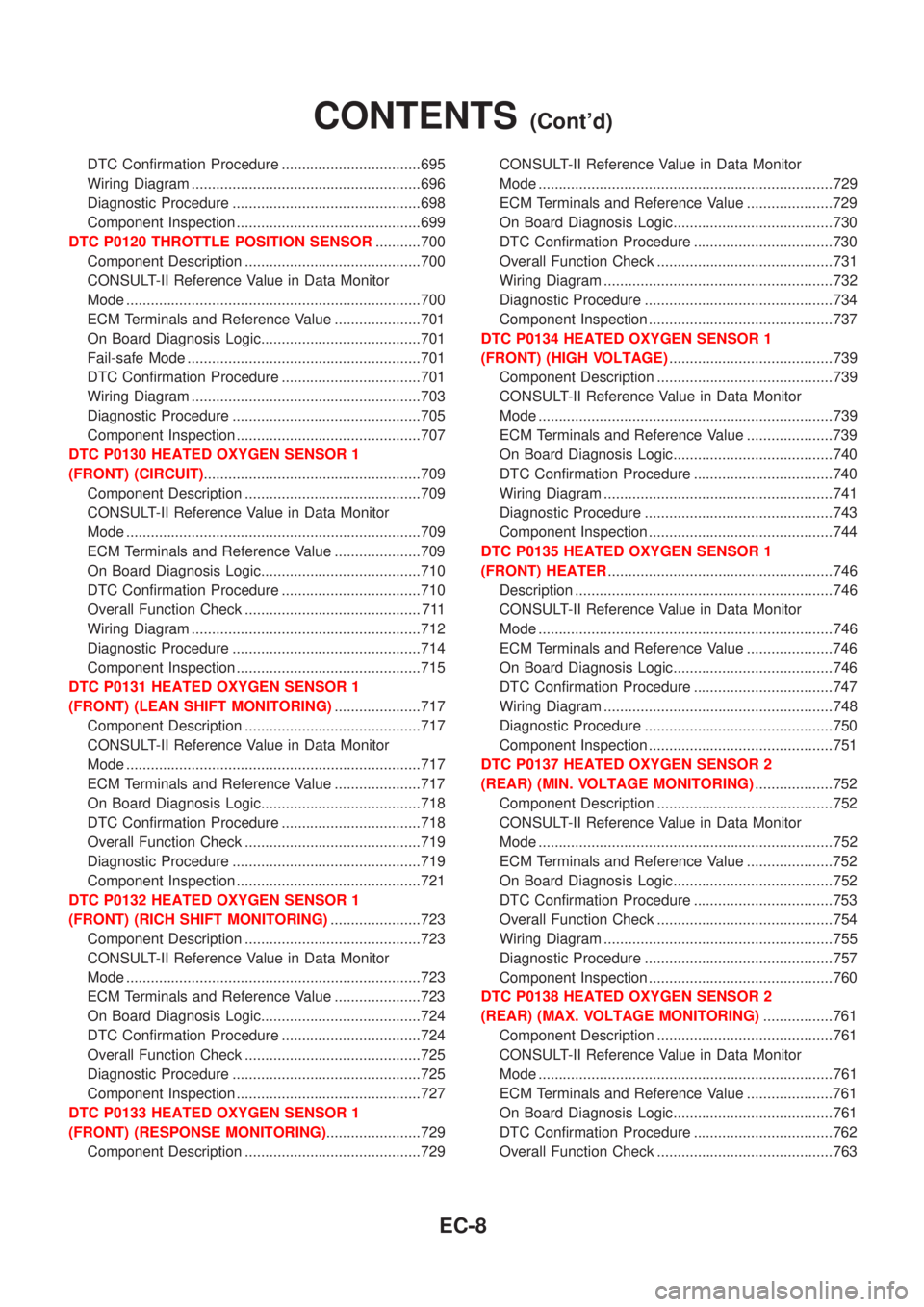
DTC Confirmation Procedure ..................................695
Wiring Diagram ........................................................696
Diagnostic Procedure ..............................................698
Component Inspection .............................................699
DTC P0120 THROTTLE POSITION SENSOR...........700
Component Description ...........................................700
CONSULT-II Reference Value in Data Monitor
Mode ........................................................................700
ECM Terminals and Reference Value .....................701
On Board Diagnosis Logic.......................................701
Fail-safe Mode .........................................................701
DTC Confirmation Procedure ..................................701
Wiring Diagram ........................................................703
Diagnostic Procedure ..............................................705
Component Inspection .............................................707
DTC P0130 HEATED OXYGEN SENSOR 1
(FRONT) (CIRCUIT).....................................................709
Component Description ...........................................709
CONSULT-II Reference Value in Data Monitor
Mode ........................................................................709
ECM Terminals and Reference Value .....................709
On Board Diagnosis Logic.......................................710
DTC Confirmation Procedure ..................................710
Overall Function Check ........................................... 711
Wiring Diagram ........................................................712
Diagnostic Procedure ..............................................714
Component Inspection .............................................715
DTC P0131 HEATED OXYGEN SENSOR 1
(FRONT) (LEAN SHIFT MONITORING).....................717
Component Description ...........................................717
CONSULT-II Reference Value in Data Monitor
Mode ........................................................................717
ECM Terminals and Reference Value .....................717
On Board Diagnosis Logic.......................................718
DTC Confirmation Procedure ..................................718
Overall Function Check ...........................................719
Diagnostic Procedure ..............................................719
Component Inspection .............................................721
DTC P0132 HEATED OXYGEN SENSOR 1
(FRONT) (RICH SHIFT MONITORING)......................723
Component Description ...........................................723
CONSULT-II Reference Value in Data Monitor
Mode ........................................................................723
ECM Terminals and Reference Value .....................723
On Board Diagnosis Logic.......................................724
DTC Confirmation Procedure ..................................724
Overall Function Check ...........................................725
Diagnostic Procedure ..............................................725
Component Inspection .............................................727
DTC P0133 HEATED OXYGEN SENSOR 1
(FRONT) (RESPONSE MONITORING).......................729
Component Description ...........................................729CONSULT-II Reference Value in Data Monitor
Mode ........................................................................729
ECM Terminals and Reference Value .....................729
On Board Diagnosis Logic.......................................730
DTC Confirmation Procedure ..................................730
Overall Function Check ...........................................731
Wiring Diagram ........................................................732
Diagnostic Procedure ..............................................734
Component Inspection .............................................737
DTC P0134 HEATED OXYGEN SENSOR 1
(FRONT) (HIGH VOLTAGE)........................................739
Component Description ...........................................739
CONSULT-II Reference Value in Data Monitor
Mode ........................................................................739
ECM Terminals and Reference Value .....................739
On Board Diagnosis Logic.......................................740
DTC Confirmation Procedure ..................................740
Wiring Diagram ........................................................741
Diagnostic Procedure ..............................................743
Component Inspection .............................................744
DTC P0135 HEATED OXYGEN SENSOR 1
(FRONT) HEATER.......................................................746
Description ...............................................................746
CONSULT-II Reference Value in Data Monitor
Mode ........................................................................746
ECM Terminals and Reference Value .....................746
On Board Diagnosis Logic.......................................746
DTC Confirmation Procedure ..................................747
Wiring Diagram ........................................................748
Diagnostic Procedure ..............................................750
Component Inspection .............................................751
DTC P0137 HEATED OXYGEN SENSOR 2
(REAR) (MIN. VOLTAGE MONITORING)...................752
Component Description ...........................................752
CONSULT-II Reference Value in Data Monitor
Mode ........................................................................752
ECM Terminals and Reference Value .....................752
On Board Diagnosis Logic.......................................752
DTC Confirmation Procedure ..................................753
Overall Function Check ...........................................754
Wiring Diagram ........................................................755
Diagnostic Procedure ..............................................757
Component Inspection .............................................760
DTC P0138 HEATED OXYGEN SENSOR 2
(REAR) (MAX. VOLTAGE MONITORING).................761
Component Description ...........................................761
CONSULT-II Reference Value in Data Monitor
Mode ........................................................................761
ECM Terminals and Reference Value .....................761
On Board Diagnosis Logic.......................................761
DTC Confirmation Procedure ..................................762
Overall Function Check ...........................................763
CONTENTS(Cont'd)
EC-8
Page 434 of 3051
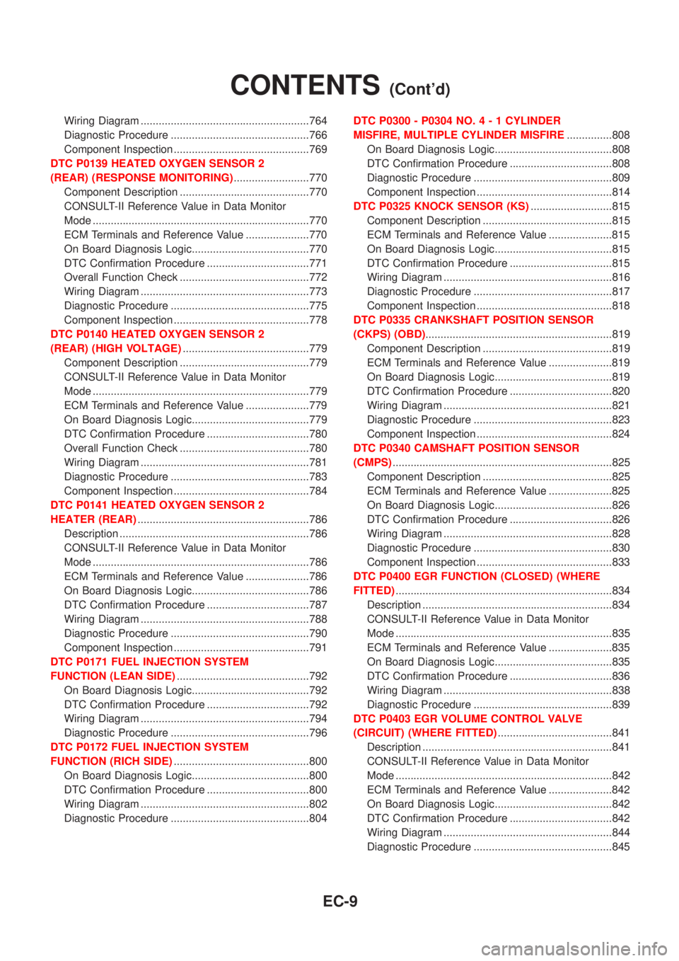
Wiring Diagram ........................................................764
Diagnostic Procedure ..............................................766
Component Inspection .............................................769
DTC P0139 HEATED OXYGEN SENSOR 2
(REAR) (RESPONSE MONITORING).........................770
Component Description ...........................................770
CONSULT-II Reference Value in Data Monitor
Mode ........................................................................770
ECM Terminals and Reference Value .....................770
On Board Diagnosis Logic.......................................770
DTC Confirmation Procedure ..................................771
Overall Function Check ...........................................772
Wiring Diagram ........................................................773
Diagnostic Procedure ..............................................775
Component Inspection .............................................778
DTC P0140 HEATED OXYGEN SENSOR 2
(REAR) (HIGH VOLTAGE)..........................................779
Component Description ...........................................779
CONSULT-II Reference Value in Data Monitor
Mode ........................................................................779
ECM Terminals and Reference Value .....................779
On Board Diagnosis Logic.......................................779
DTC Confirmation Procedure ..................................780
Overall Function Check ...........................................780
Wiring Diagram ........................................................781
Diagnostic Procedure ..............................................783
Component Inspection .............................................784
DTC P0141 HEATED OXYGEN SENSOR 2
HEATER (REAR).........................................................786
Description ...............................................................786
CONSULT-II Reference Value in Data Monitor
Mode ........................................................................786
ECM Terminals and Reference Value .....................786
On Board Diagnosis Logic.......................................786
DTC Confirmation Procedure ..................................787
Wiring Diagram ........................................................788
Diagnostic Procedure ..............................................790
Component Inspection .............................................791
DTC P0171 FUEL INJECTION SYSTEM
FUNCTION (LEAN SIDE)............................................792
On Board Diagnosis Logic.......................................792
DTC Confirmation Procedure ..................................792
Wiring Diagram ........................................................794
Diagnostic Procedure ..............................................796
DTC P0172 FUEL INJECTION SYSTEM
FUNCTION (RICH SIDE).............................................800
On Board Diagnosis Logic.......................................800
DTC Confirmation Procedure ..................................800
Wiring Diagram ........................................................802
Diagnostic Procedure ..............................................804DTC P0300 - P0304 NO.4-1CYLINDER
MISFIRE, MULTIPLE CYLINDER MISFIRE...............808
On Board Diagnosis Logic.......................................808
DTC Confirmation Procedure ..................................808
Diagnostic Procedure ..............................................809
Component Inspection .............................................814
DTC P0325 KNOCK SENSOR (KS)...........................815
Component Description ...........................................815
ECM Terminals and Reference Value .....................815
On Board Diagnosis Logic.......................................815
DTC Confirmation Procedure ..................................815
Wiring Diagram ........................................................816
Diagnostic Procedure ..............................................817
Component Inspection .............................................818
DTC P0335 CRANKSHAFT POSITION SENSOR
(CKPS) (OBD)..............................................................819
Component Description ...........................................819
ECM Terminals and Reference Value .....................819
On Board Diagnosis Logic.......................................819
DTC Confirmation Procedure ..................................820
Wiring Diagram ........................................................821
Diagnostic Procedure ..............................................823
Component Inspection .............................................824
DTC P0340 CAMSHAFT POSITION SENSOR
(CMPS).........................................................................825
Component Description ...........................................825
ECM Terminals and Reference Value .....................825
On Board Diagnosis Logic.......................................826
DTC Confirmation Procedure ..................................826
Wiring Diagram ........................................................828
Diagnostic Procedure ..............................................830
Component Inspection .............................................833
DTC P0400 EGR FUNCTION (CLOSED) (WHERE
FITTED)........................................................................834
Description ...............................................................834
CONSULT-II Reference Value in Data Monitor
Mode ........................................................................835
ECM Terminals and Reference Value .....................835
On Board Diagnosis Logic.......................................835
DTC Confirmation Procedure ..................................836
Wiring Diagram ........................................................838
Diagnostic Procedure ..............................................839
DTC P0403 EGR VOLUME CONTROL VALVE
(CIRCUIT) (WHERE FITTED)......................................841
Description ...............................................................841
CONSULT-II Reference Value in Data Monitor
Mode ........................................................................842
ECM Terminals and Reference Value .....................842
On Board Diagnosis Logic.......................................842
DTC Confirmation Procedure ..................................842
Wiring Diagram ........................................................844
Diagnostic Procedure ..............................................845
CONTENTS(Cont'd)
EC-9
Page 436 of 3051
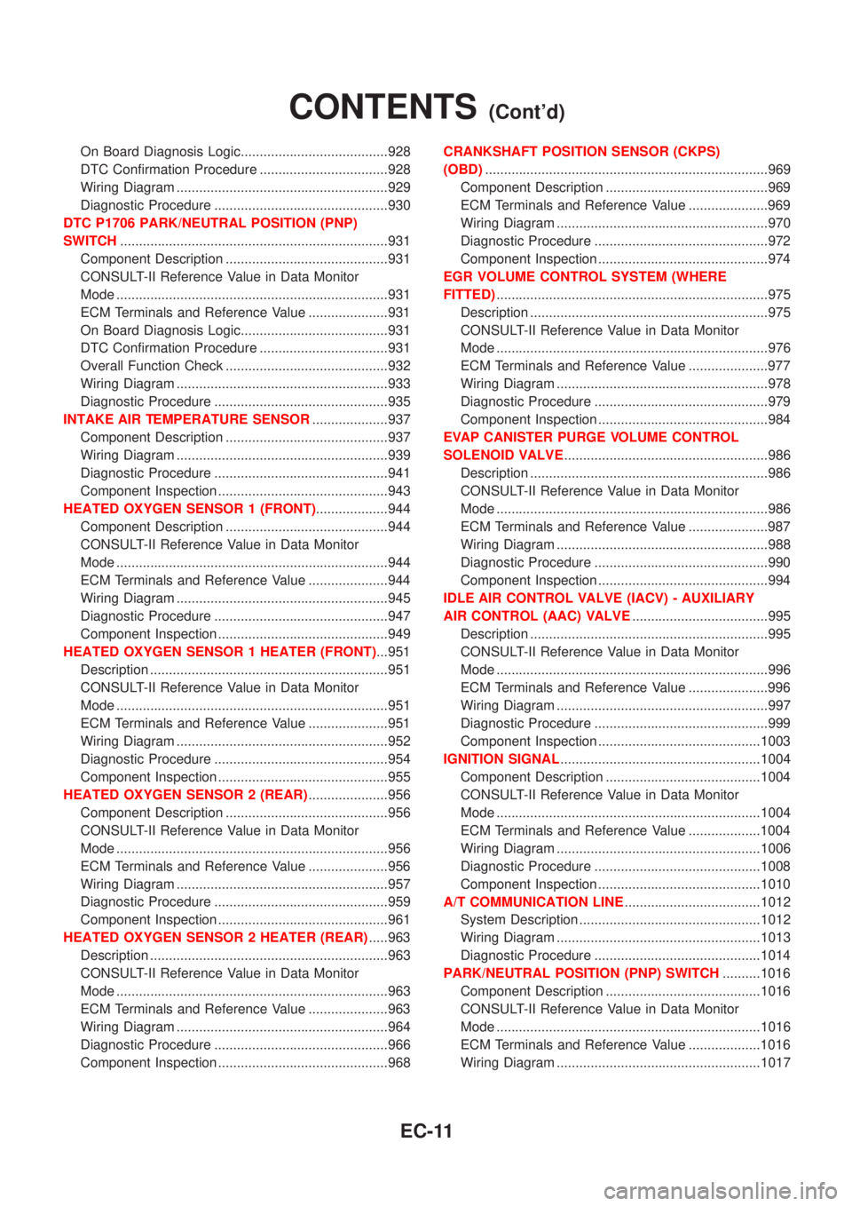
On Board Diagnosis Logic.......................................928
DTC Confirmation Procedure ..................................928
Wiring Diagram ........................................................929
Diagnostic Procedure ..............................................930
DTC P1706 PARK/NEUTRAL POSITION (PNP)
SWITCH.......................................................................931
Component Description ...........................................931
CONSULT-II Reference Value in Data Monitor
Mode ........................................................................931
ECM Terminals and Reference Value .....................931
On Board Diagnosis Logic.......................................931
DTC Confirmation Procedure ..................................931
Overall Function Check ...........................................932
Wiring Diagram ........................................................933
Diagnostic Procedure ..............................................935
INTAKE AIR TEMPERATURE SENSOR....................937
Component Description ...........................................937
Wiring Diagram ........................................................939
Diagnostic Procedure ..............................................941
Component Inspection .............................................943
HEATED OXYGEN SENSOR 1 (FRONT)...................944
Component Description ...........................................944
CONSULT-II Reference Value in Data Monitor
Mode ........................................................................944
ECM Terminals and Reference Value .....................944
Wiring Diagram ........................................................945
Diagnostic Procedure ..............................................947
Component Inspection .............................................949
HEATED OXYGEN SENSOR 1 HEATER (FRONT)...951
Description ...............................................................951
CONSULT-II Reference Value in Data Monitor
Mode ........................................................................951
ECM Terminals and Reference Value .....................951
Wiring Diagram ........................................................952
Diagnostic Procedure ..............................................954
Component Inspection .............................................955
HEATED OXYGEN SENSOR 2 (REAR).....................956
Component Description ...........................................956
CONSULT-II Reference Value in Data Monitor
Mode ........................................................................956
ECM Terminals and Reference Value .....................956
Wiring Diagram ........................................................957
Diagnostic Procedure ..............................................959
Component Inspection .............................................961
HEATED OXYGEN SENSOR 2 HEATER (REAR).....963
Description ...............................................................963
CONSULT-II Reference Value in Data Monitor
Mode ........................................................................963
ECM Terminals and Reference Value .....................963
Wiring Diagram ........................................................964
Diagnostic Procedure ..............................................966
Component Inspection .............................................968CRANKSHAFT POSITION SENSOR (CKPS)
(OBD)...........................................................................969
Component Description ...........................................969
ECM Terminals and Reference Value .....................969
Wiring Diagram ........................................................970
Diagnostic Procedure ..............................................972
Component Inspection .............................................974
EGR VOLUME CONTROL SYSTEM (WHERE
FITTED)........................................................................975
Description ...............................................................975
CONSULT-II Reference Value in Data Monitor
Mode ........................................................................976
ECM Terminals and Reference Value .....................977
Wiring Diagram ........................................................978
Diagnostic Procedure ..............................................979
Component Inspection .............................................984
EVAP CANISTER PURGE VOLUME CONTROL
SOLENOID VALVE......................................................986
Description ...............................................................986
CONSULT-II Reference Value in Data Monitor
Mode ........................................................................986
ECM Terminals and Reference Value .....................987
Wiring Diagram ........................................................988
Diagnostic Procedure ..............................................990
Component Inspection .............................................994
IDLE AIR CONTROL VALVE (IACV) - AUXILIARY
AIR CONTROL (AAC) VALVE....................................995
Description ...............................................................995
CONSULT-II Reference Value in Data Monitor
Mode ........................................................................996
ECM Terminals and Reference Value .....................996
Wiring Diagram ........................................................997
Diagnostic Procedure ..............................................999
Component Inspection ...........................................1003
IGNITION SIGNAL.....................................................1004
Component Description .........................................1004
CONSULT-II Reference Value in Data Monitor
Mode ......................................................................1004
ECM Terminals and Reference Value ...................1004
Wiring Diagram ......................................................1006
Diagnostic Procedure ............................................1008
Component Inspection ...........................................1010
A/T COMMUNICATION LINE....................................1012
System Description ................................................1012
Wiring Diagram ......................................................1013
Diagnostic Procedure ............................................1014
PARK/NEUTRAL POSITION (PNP) SWITCH..........1016
Component Description .........................................1016
CONSULT-II Reference Value in Data Monitor
Mode ......................................................................1016
ECM Terminals and Reference Value ...................1016
Wiring Diagram ......................................................1017
CONTENTS(Cont'd)
EC-11